 Open Access Article
Highly porous CO2 hydrate generation aided by silica nanoparticles for potential secure storage of CO2 and desalination†
Ijung Kim a,
Michael Noleb,
Sunghyun Jangb,
Saebom Kob,
Hugh Daigleb,
Gary A. Popeb and
Chun Huh*b
aDepartment of Civil and Environmental Engineering, Western New England University, 1215 Wilbraham Rd., Springfield, MA 01119, USA. E-mail: ijung.kim@wne.edu
bDepartment of Petroleum and Geosystems Engineering, The University of Texas at Austin, 200 E. Dean Keeton St., Stop C0300, Austin, TX 78712, USA. E-mail: chunhuh@mail.utexas.edu
First published on 31st January 2017
Abstract
We report a new way of storing CO2 in a highly porous hydrate structure, stabilized by silica nanoparticles (NPs). Such a porous CO2 hydrate structure was generated either by cooling down NP-stabilized CO2-in-seawater foams, or by gently mixing CO2 and seawater that contains silica NPs under CO2 hydrate-generating conditions. With the highly porous structure, enhanced desalination was also achievable when the partial meltdown of CO2 hydrate was allowed.
In situ generation of CO2 hydrate at deep seabeds has been studied extensively as an economic way of sequestering anthropogenic CO2,1–3 since at the deep sea's near-freezing temperature and high hydrostatic pressure conditions, CO2 hydrate can be naturally formed from a mixture of CO2 and seawater.4,5 Being solid with its density slightly higher than that of seawater, the CO2 hydrate can potentially stay at the deep seabed indefinitely.6,7 This highly attractive concept, however, has two shortcomings: first, the hydrate formation is known to occur at the interface between CO2 and water and, once a hydrate layer is formed at the CO2/water interface,8 the layer serves as a barrier to further contact between CO2 and water. Consequently, subsequent hydrate generation is considerably slowed down. Therefore, a vigorous mixing of CO2 and water, thus a significant input of mechanical energy, is needed not only to generate as much CO2/water interfacial area as possible by eliminating heat and mass transfer resistance,9 but also to disperse the locally trapped salt that was rejected from the hydrate.10 Second, CO2 hydrate generally consists of 5.8–7.8 molecules of water per CO2 molecule,11 which means that in order to store a meaningful volume of CO2 in hydrate form, an inordinate amount of water also has to be processed.
Our finding, here, is that a highly porous CO2 hydrate structure can be generated by employing high internal-volume CO2-in-water foam that is stabilized with hydrophilic silica nanoparticles (NPs). The concept was derived from two groups of composite materials that are based on NP-stabilized dispersions with a high internal-phase volume fraction. The first is CO2-in-water foams that can be employed as an almost water-less fracturing fluid for oil and gas production;12 the other is polymeric foams with high internal void spaces (polyHIPE), which are used as ultralight-weight, high-strength materials for a variety of chemical and biomedical applications.13,14 The generation of both “water-less” CO2 foam and polyHIPE requires the use of NPs or colloidal particles to stabilize the high internal-phase volume fraction dispersion, which has its continuous external phase in the form of very thin lamellae. In order to maintain the stability of such thin films, polymer or viscoelastic surfactant is generally needed in addition to NPs.15 In our case, the CO2 hydrate particulates generated next to NPs (that straddle the CO2/water interface; see Fig. 1) appear to provide certain structural rigidity for the lamella's integrity. This is in a sense similar to polyHIPE in which, once dispersion is formed, thin lamellae polymerize and solidify, thereby generating a high-porosity, low-permeability, sturdy structure. Earlier studies16–18 found that, when a water-in-CO2 dispersion is generated by way of “dry water” (water-in-air Pickering dispersion, stabilized with hydrophobic silica NPs19) and is subsequently brought to the hydrate-generating condition, hydrate generation kinetics are significantly enhanced. Such enhancement is in line with earlier observations that the presence of silica surface enhances CO2 hydrate nucleation and growth. Importantly, the enhancement may result not only from the large solid surface area available from silica NPs, but also from the generation of tremendous lengths of three-phase (CO2/water/silica) contact line on the NPs adsorbed at the CO2/water interfaces of the dispersion. Recent molecular dynamics simulations20 showed that the CO2/water/silica contact line zone serves as a highly favourable nucleation site for CO2 hydrates. Since the hydrophilic NPs stabilizes CO2-in-water dispersions while hydrophobic NPs stabilize water-in-CO2 dispersion, and since the use of hydrophilic NPs such as zinc oxide21 and graphite22 to enhance CO2 hydrate generation has been reported, we experimentally investigated the effect of the hydrophilic silica NPs on the CO2 hydrate generation and its structure. In addition to much lower cost of manufacturing, the hydrophilic silica NP can be easily dispersed in the water, without going through somewhat tedious step of “dry water” generation. Two important requirements for the hydrophilic NP's surface property are: (i) the NPs should have long-term dispersion stability in seawater; and (ii) they should have the hydrophilicity to form stable CO2-in-water foams when sufficient mechanical energy input is applied. These requirements were verified for the NPs we used, based on our earlier studies.23,24
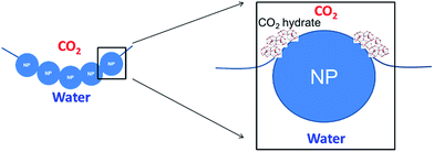 | ||
| Fig. 1 The presence of hydrophilic nanoparticles at the CO2–water interface increases the length of the three-phase contact line, improving CO2 hydrate nucleation. | ||
CO2 hydrate formation experiments
CO2 hydrate was generated in two different ways: (i) via prior generation of CO2-in-seawater foam and (ii) by gentle mixing of CO2 and seawater. Similar tests were conducted with DI water, also, CO2 hydrate was generated via “dry water” (hydrophobic nanoparticle-stabilized water dispersion in air) as a supplementary study (details in ESI†).The synthetic seawater (ASTM D 1141, Ricca Chemical Company®, USA) and the liquid CO2 (Praxair, USA) were employed to generate CO2 hydrate in the 12.5 mL sapphire cell (Separex, France). For nanoparticles, the nominal 5 nm-spherical hydrophilic silica nanoparticles coated with polyethylene glycol (3M, USA) were used.
For the CO2 hydrate via CO2-in-seawater foams, the nanoparticle-stabilized CO2 foam generating system in previous study25 was utilized as shown in Fig. 2(A). The CO2 and seawater with 1 wt% hydrophilic nanoparticles were co-injected into a sandpack (filled with 350 μm Ottawa sand) by HPLC pump (1500 HPLC, Supercritical Fluid Technologies, Inc., USA) and high pressure syringe pump (500D, Teledyne ISCO, Inc., USA), generating CO2-in-seawater foams through the effluent line at the ambient temperature. The total flow rate was controlled at 10 mL min−1 with a constant volume fraction of CO2 at 0.75. At the flow condition, the interstitial velocity, shear rate, and residence time were 3.39 cm s−1, 10![[thin space (1/6-em)]](https://www.rsc.org/images/entities/char_2009.gif) 600 s−1, and 9 s, respectively. The entire system pressure was maintained at 11.7 MPa by the back pressure regulator (Core Laboratories, USA). The pressure was also monitored by the pressure gauge (Swagelok, USA) connected to the sapphire cell. When the CO2-in-seawater foam fully filled the sapphire cell, it was then kept at 4 °C in a stationary condition for 24 h (Fig S3†).
600 s−1, and 9 s, respectively. The entire system pressure was maintained at 11.7 MPa by the back pressure regulator (Core Laboratories, USA). The pressure was also monitored by the pressure gauge (Swagelok, USA) connected to the sapphire cell. When the CO2-in-seawater foam fully filled the sapphire cell, it was then kept at 4 °C in a stationary condition for 24 h (Fig S3†).
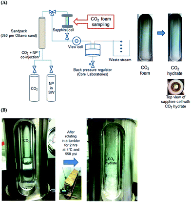 | ||
| Fig. 2 Experimental system to generate CO2 hydrate via (A) CO2-in-seawater foam and (B) gentle mixing of CO2 and seawater. | ||
For the hydrate formation by gentle mixing of CO2 and seawater, the entire set-up was placed in the 4 °C cold room overnight prior to the test. The sapphire cell was filled with 6 mL of seawater with or without 1 wt% hydrophilic nanoparticles, followed by the pressurization with CO2 up to 3.8 MPa. CO2 was stored in a pressure vessel which was held at 3.8 MPa at 4 °C and connected to the sapphire cell to pressurize it. Once the cell was pressurized, the initial test pressure was confirmed by the pressure gauge (Kodiak Controls Inc., USA) attached to the cell. Then, the sapphire cell was placed in a tumbler which rotated at 7 rpm for 2 h. The rotating speed of the tumbler was selected to keep the CO2 hydrate generation in a gentle mixing condition.
Overall, the following improvements in experimental procedure over the earlier reported16–18 were made. First, the entire generation process was carried out in a 4 °C cold room to ensure a constant temperature condition. The cold room was designed to keep 4 °C constantly with a real-time temperature monitoring panel. Second, sapphire cells with pressure control were employed to directly observe the progress of hydrate generation process. After the visual observation that the hydrate generation was established, the cell was depressurized, the generated hydrate was drained of any excess water and was immediately taken in an ice bath to the cold-stage scanning electron microscopy (SEM) to obtain microscopic structural images (details in ESI†).
Note that water used in our main experiments reported here was synthetic seawater. Although the water that forms hydrate cage does not include any salts, seawater with high salt content can still be included in between hydrate aggregates during the process of the rapid CO2 hydrate generation.26 Therefore, the Na+, Mg2+, and Ca2+ ion concentrations of the hydrate samples taken from the depressurized cell were measured by ion chromatography (Dionex ICS-1100, Thermo Scientific, USA) equipped with cation exchange column (IonPac CS12A, Thermo Scientific, USA) to quantify their change from the pre-hydrate concentrations, in order to approximately estimate the extent of seawater trapping. To further analyze the effect of CO2 hydrate melting on the trapped ion concentrations, a part of CO2 hydrate taken out of the sapphire cell was sampled for the ion concentration analysis before melting, and the rest of the hydrate was placed on a disposable wiper (Kimwipes, Kimberly-Clark, USA) to drain the trapped seawater for 10 min at 4 °C and ambient pressure condition, as the hydrate partially melted slowly. During the partial melting process,27 the CO2 hydrate was sampled at 5 and 10 min, respectively, which was allowed to melt completely for the ion chromatography analysis.
SEM observations of different hydrate structures
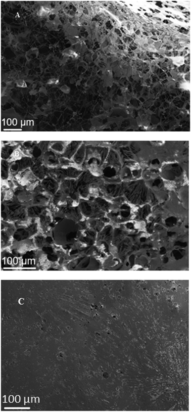
Fig. 3(A) shows the hydrate generated from the pre-formed CO2-in-seawater foam stabilized with hydrophilic silica NPs. As described above, the lamella's stability was maintained by the NPs adsorbed on its two interfaces, and the newly generated hydrates attached to the NPs appear to provide additional rigidity to the lamellae. With the sapphire cell depressurization, the CO2 bubbles would have expanded and burst the lamellae; however, unlike the conventional foam lamellae which, when destabilized, would immediately contract and disappear, the CO2 hydrate-covered lamellae still left a considerable degree of “skeletal boundaries”, similar to the polymerized polyHIPE structure. This suggests that, as discussed above with the molecular dynamics simulations,20 the CO2 hydrate generation from CO2 foam occurred at three-phase contact line throughout the lamellae, forming a highly porous NP-stabilized CO2 hydrate structure even after depressurization.Fig. 3(B) shows a SEM image of the hydrate generated from gentle mixing of CO2 and hydrophilic silica NP-containing seawater in a tumbler. At ambient conditions, such a gentle mixing cannot produce stable CO2-in-water foam, because the adsorption of NPs to the CO2/water interface requires to overcome a certain energy barrier.28 Brought to the hydrate-generating condition, however, it appears that the CO2-in-seawater foam generation was possible even with only moderate energy input, from synergy between the newly generated hydrate at the CO2/water interface and the NPs that were attached to the hydrates and thus more easily brought to the CO2/water interface. The adsorbed NPs, in turn, would enhance further hydrate generation at three-phase contact lines. The image suggests that the lamellae did not have as much rigidity as the case of pre-generated foam (Fig. 3(A)), with fewer “skeletal boundaries” remaining after the depressurization. This is probably because not as many NPs were able to be adsorbed at the bubble interface, due to insufficient mixing energy input. Also the larger pore size suggests larger CO2 bubbles. Nevertheless, it seems that the NP-stabilized CO2 hydrate structure, even generated with gentle mixing only, could hold a substantial volume of CO2 throughout the numerous lamellae. The NPs added to water thus appear to contribute to formation of a highly porous CO2 hydrate structure by way of generation of CO2 foams with highly stable, NP-stabilized lamellae.
Fig. 3(C) shows the CO2 hydrate generated from gentle mixing of CO2 and seawater, but without NPs. The planar surface indicates that there was little possibility to form stable CO2 bubbles without the NPs. As a result, the CO2/seawater interface as a large plane served as the CO2 hydrate generation sites, leading to a planar growth in the entire cell. This type of surface structure was also found with the CO2 hydrate generated by gentle mixing of CO2 and DI water (Fig. S1(A)†). This also suggests that the stability of the CO2 hydrate-induced CO2/seawater dispersion in the absence of NPs is rather tenuous, and the ability of such hydrate structure to hold CO2 is quite uncertain.
Fig. 4 shows a nanoscale SEM image of CO2 hydrate generated by gentle mixing of CO2 and seawater with NPs (see Fig. 3(B)). The skeletal structure, which is the vestige of the CO2 foam lamellae, was clearly captured, displaying its thickness around 200–500 nm. The swollen three-way junction appears to represent a plateau border with the formerly continuous aqueous phase.29 This SEM image suggests simultaneous CO2 foam generation and hydrate generation. Although the threshold shear rate is required to overcome the adsorption energy barrier24 for CO2 foam generation, little has been studied for the CO2 foam generation at such a low temperature. The CO2 foam stability was known to increase as temperature decreases. Also, the increased CO2 density at such a low temperature would require less mechanical mixing for CO2 foam generation.23 In addition, the nucleation and the growth of CO2 hydrate in the CO2/seawater mixture might provide additional shear to the fluid as small solid CO2 hydrate particles or aggregates rotate in it.
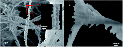 | ||
| Fig. 4 Nanoscale SEM image of CO2 hydrate formed by gentle mixing of CO2 and seawater with nanoparticles: focusing on (A) a rod and (B) a three-way junction. | ||
Salinities in different hydrate structures
In principle, CO2 hydrate generation can be a good desalination method because hydrate molecular cage contains water with zero salinity. However, when CO2 hydrate is generated from seawater, the seawater inclusion among CO2 hydrate aggregates is inevitable, leaving a certain level of salinity. Since the highly porous CO2 hydrate would trap less seawater due to their more internally connected structure, it was desirable to measure the salinity from the CO2 hydrate samples. Because it is difficult to distinguish the hydrate from the trapped seawater based on the SEM images of the skeletal structure, the following indirect way of estimating the respective mass fractions of major salt ions was attempted. After the CO2 hydrate samples were taken out from the depressurized sapphire cell and excess seawater was drained off, three different samples were prepared; one taken immediately after the seawater drainage; and two taken after 5 and 10 minutes of the partial melting of CO2 hydrate sample at 4 °C for the further drainage and removal of the trapped seawater. Then, the concentration of three major cations (Na+, Mg2+, and Ca2+ ion initially 1.13%, 0.06%, and 0.13%, respectively) in seawater was measured from these three different samples. Fig. 5 shows the overall removal efficiency (measured concentration over original seawater concentration) of the salt ions. Without partial melting, the removal efficiency was 6.68–9.24% higher with NPs than without NPs. When the samples were taken after the partial melting was allowed for 10 min, the removal efficiency was increased up to 65.30% (without NPs) and 86.26% (with NPs), supporting the greater drainage rate of the trapped seawater with NPs, specifically, with the highly porous structure. The ESI data regarding the removal efficiency is included in Table S1.† The qualitatively similar removal trend was obtained over the series of tests although some fluctuations in the measurements were also observed because the identical CO2 hydrate surface area was difficult to obtain. Therefore, the constant test condition with a detailed control protocol should be maintained to minimize the fluctuations in the removal efficiency. Considering the similar trend in removal pattern among the major ions tested here, other minor salts are expected to show such removal pattern as well. In fact, for the hydrate-based desalination process,30 the salt trapping turned out to be a major hindrance for its practical development. The facts that the NP-aided CO2 hydrate structure contained much less trapped salt, and that the drainage of trapped seawater was achievable by simple partial melting of CO2 hydrate, offer an intriguing possibility that NP-aided CO2 hydrate-based desalination process may provide an economic way of producing low-salinity water, e.g., for the recently developed low-salinity enhanced oil recovery process for offshore oilfields.31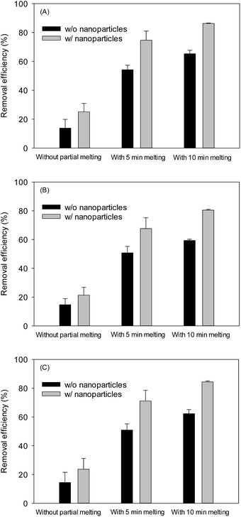 | ||
| Fig. 5 Effect of nanoparticles on removal efficiency of major cations in seawater via CO2 hydrate followed by a partial melting: (A) Na+, (B) Mg2+, and (C) Ca2+. | ||
Conclusions
Based on the CO2 hydrate formation mechanism, it is expected that the diffusion of water to liquid CO2 would occur along with the hydrophilic silica NP surface located at the CO2/water interface, offering numerous sites for CO2 hydrate nucleation. In addition, the conversion of CO2-in-seawater foams to CO2 hydrate shown in this study demonstrates the CO2 hydrate could be pre-shaped in a lamellar structure resulting in a highly porous CO2 hydrate.The generation of such highly porous CO2 hydrate structure, in situ either in geological formations or at subsea, has a couple of potential applications. First, such porous hydrate structures containing CO2 could be securely sequestered in quantity in the shallow subsurface of deep-sea sediments, which are abundantly available worldwide. Second, as described above, an economic desalination process could be developed via natural formation of NP-stabilized CO2 hydrate, at subsea, to obtain low-salinity water for injection for enhanced oil recovery from offshore oil reservoirs. The currently available desalination options are either too costly or difficult to implement on platforms. Such utilization of CO2 in hydrate form will improve the overall economics of CO2 sequestration as well as offshore oilfield operation, so that CO2 can be sequestered in truly meaningful quantities.
Acknowledgements
This research was supported by the U.S. Department of Energy, Office of Science, Office of Basic Energy Science under contract no. DE-SC0001114. The authors thank Dr Lynn Katz for the use of the cold room (4 °C), Dr Dwight Romanovicz for assistance with the SEM measurements, and 3M® Company (Dr Jim Baran) for the donation of silica nanoparticles.References
- P. Linga, R. Kumar and P. Englezos, J. Hazard. Mater., 2007, 149, 625–629 CrossRef CAS PubMed.
- H. Tajima, A. Yamasaki, F. Kiyono and H. Teng, AIChE J., 2004, 50, 871–878 CrossRef CAS.
- B. Tohidi, J. H. Yang, M. Salehabadi, R. Anderson and A. Chapoy, Environ. Sci. Technol., 2010, 44, 1509–1514 CrossRef CAS PubMed.
- K. Z. House, D. P. Schrag, C. F. Harvey and K. S. Lackner, Proc. Natl. Acad. Sci. U. S. A., 2006, 103, 12291–12295 CrossRef CAS PubMed.
- K. Ohgaki, Y. Makihara and K. Takano, J. Chem. Eng. Jpn., 1993, 26, 558–564 CrossRef CAS.
- S. Lee, L. Liang, D. Riestenberg, O. R. West, C. Tsouris and E. Adams, Environ. Sci. Technol., 2003, 37, 3701–3708 CrossRef CAS PubMed.
- D. E. Riestenberg, C. Tsouris, P. G. Brewer, E. T. Peltzer, P. Walz, A. C. Chow and E. E. Adams, Environ. Sci. Technol., 2005, 39, 7287–7293 CrossRef CAS PubMed.
- F. Lehmkuhler, M. Paulus, C. Sternemann, D. Lietz, F. Venturini, C. Gutt and M. Tolan, J. Am. Chem. Soc., 2009, 131, 585–589 CrossRef PubMed.
- M. A. Clarke and P. R. Bishnoi, Chem. Eng. Sci., 2005, 60, 695–709 CrossRef CAS.
- C. Tsouris, P. Szymcek, P. Taboada-Serrano, S. McCallum, P. Brewer, E. Peltzer, P. Walz, E. Adams, A. Chow and W. Johnson, Energy Fuels, 2007, 21, 3300–3309 CrossRef CAS.
- D. Kyung, H.-K. Lim, H. Kim and W. Lee, Environ. Sci. Technol., 2015, 49, 1197–1205 CrossRef CAS PubMed.
- Z. Xue, A. J. Worthen, C. Da, A. Qajar, I. R. Ketchum, S. Alzobaidi, C. Huh, M. Prodanovic and K. P. Johnston, Langmuir, 2015, 32, 28–37 CrossRef PubMed.
- I. Pulko, M. Kolar and P. Krajnc, Sci. Total Environ., 2007, 386, 114–123 CrossRef CAS PubMed.
- C. Zhao, E. Danish, N. R. Cameron and R. Kataky, J. Mater. Chem., 2007, 17, 2446–2453 RSC.
- S. Siripurapu, J. M. DeSimone, S. A. Khan and R. J. Spontak, Macromolecules, 2005, 38, 2271–2280 CrossRef CAS.
- B. O. Carter, W. Wang, D. J. Adams and A. I. Cooper, Langmuir, 2009, 26, 3186–3193 CrossRef PubMed.
- F. Farhang, A. V. Nguyen and M. A. Hampton, Energy Fuels, 2014, 28, 1220–1229 CrossRef CAS.
- F. Farhang, A. V. Nguyen and K. B. Sewell, Energy Fuels, 2014, 28, 7025–7037 CrossRef CAS.
- B. P. Binks and R. Murakami, Nat. Mater., 2006, 5, 865–869 CrossRef CAS PubMed.
- D. Bai, G. Chen, X. Zhang and W. Wang, Langmuir, 2012, 28, 7730–7736 CrossRef CAS PubMed.
- M. Mohammadi, A. Haghtalab and Z. Fakhroueian, J. Chem. Thermodyn., 2016, 96, 24–33 CrossRef CAS.
- S.-d. Zhou, Y.-s. Yu, M.-m. Zhao, S.-l. Wang and G.-z. Zhang, Energy Fuels, 2014, 28, 4694–4698 CrossRef CAS.
- A. J. Worthen, H. G. Bagaria, Y. Chen, S. L. Bryant, C. Huh and K. P. Johnston, J. Colloid Interface Sci., 2013, 391, 142–151 CrossRef CAS PubMed.
- T. Zhang, M. J. Murphy, H. Yu, H. G. Bagaria, K. Y. Yoon, B. M. Nielson, C. W. Bielawski, K. P. Johnston, C. Huh and S. L. Bryant, SPE J., 2014, 20, 667–677 CrossRef.
- I. Kim, A. J. Worthen, K. P. Johnston, D. A. DiCarlo and C. Huh, J. Nanopart. Res., 2016, 18, 82–93 CrossRef.
- A. P. Camps, Hydrate formation in near surface ocean sediments, PhD thesis, University of Leicester, 2008.
- W. Gu, Y.-B. Lin, Y.-J. Xu, W.-B. Chen, J. Tao and S. Yuan, Cold Reg. Sci. Technol., 2013, 86, 133–141 CrossRef.
- B. P. Binks and T. S. Horozov, Colloidal particles at liquid interfaces, Cambridge University Press, 2006 Search PubMed.
- C. J. W. Breward and P. D. Howell, J. Fluid Mech., 2002, 458, 379–406 CAS.
- K. Park, S. Y. Hong, J. W. Lee, K. C. Kang, Y. C. Lee, M.-G. Ha and J. D. Lee, Desalination, 2011, 274, 91–96 CrossRef CAS.
- N. Morrow and J. Buckley, J. Pet. Technol., 2011, 63, 106–112 CrossRef.
Footnote |
| † Electronic supplementary information (ESI) available: Detailed microscopic analysis, CO2 hydrate generation with DI water and dry water, temperature, CO2 equilibrium curve, and ion removal efficiency data. See DOI: 10.1039/c6ra26366f |
| This journal is © The Royal Society of Chemistry 2017 |

