 Open Access Article
Creative Commons Attribution 3.0 Unported Licence
Synthesis and characterization of a plasma carbon aerosol coated sponge for recyclable and efficient separation and adsorption†
A. J. Wu ,
X. D. Li,
J. Yang and
J. H. Yan*
State Key Laboratory of Clean Energy Utilization, Institute for Thermal Power Engineering, Zhejiang University, Hangzhou 310027, P. R. China. E-mail: yanjh@zju.edu.cn
First published on 30th January 2017
Abstract
A plasma-generated carbon aerosol, with the merits of high surface area, abundant porosity and high crystallinity, is a mass synthesized by-product from direct methane conversion in the production of syngas or hydrogen. In the present work, a carbon aerosol produced by rotating gliding arc (RGA) plasma was firstly incorporated with a commercial sponge to fabricate a highly selective and hydrophobic adsorption material. The properties of the carbon aerosol and its derived sponge were comprehensively characterized. By a simple dip-coating method, the wettability of the pristine sponge was altered, which was attributed to the plasma coating of the carbon aerosol. The modified sponge demonstrated an effective and selective adsorption ability for a wide range of oils and solvents, with the maximum adsorption capacity of up to 86 times its own weight. Moreover, the used sponge could be easily recovered by simple evaporation or manual squeezing, while maintaining approximately 100% of its starting adsorption capacity over 5 adsorption-recovery cycles. Such a plasma carbon aerosol coated sponge exhibits a great prospect as a cost-efficient, recyclable and scalable material in separation and adsorption for water treatment.
Introduction
Over the past years, water pollution from crude oil, industrial effluents and toxic chemical solvents has become a global environmental and ecological challenge, which imperatively requires an effective and economic strategy to address its threats to the ecosystem and human health.1,2 Utilization of adsorbents in the treatment of water pollution is regarded as one of most facile and effective approaches, with the merits of low cost, good recyclability, high selectivity and large handling capacity.3 In fact, there are various types of adsorbent materials, including natural substances,4 polymers and resins,5 silica and nanocomposites,6,7 etc. Amongst them, carbon based adsorbents, such as active carbon,8 carbon-nanotubes (CNTs)/CNTs sponges,9,10 and graphene aerogels/sponges,2,11 emerge as the most promising candidates and have been widely investigated in oil–water separation, organic solvent adsorption and removal of heavy metals. For example, spongy graphene demonstrated effective adsorption for petroleum products, fats and ketones, with the largest capacity up to 86 times of the pristine weight.12 The synthesized p-phenylenediamine modified CNTs exhibited a water contact angle of 140.8°, and could uptake oil at 3 times of its own weight.10 However, sophisticated procedures, hazardous chemicals and expensive precursors are necessary to synthesize such adsorbents, which greatly hampers their scalable production for potential applications.2 In addition, the aforementioned carbon based adsorbents are usually prone to collapse in practical adsorption due to its fragile nature, leading to a low efficiency in adsorption and a high risk to introduce extra pollution to the environment.13Herein, dip-coating is introduced as a facile, cheap and eco-benign method to fabricate carbon-based adsorbents. Using a commercial melamine sponge as 3D porous skeleton scaffolds, carbon materials such as CNTs, graphene and carbon soot are easily coated on the sponge, switching the hydrophilic surface into a hydrophobic one while retaining oleophilic property of the pristine sponge.1,11,14 For instance, sponge covered with carbon soot indicated a high adsorption capacity for various oils while repelled water completely, and the highest water contact angle could reach 132°.1 Facile coating of CNTs-PDA with polyurethane sponge could quickly and selectively absorbed various kinds of oils up to 34.9 times of its own weight.15 The graphene coated melamine sponge demonstrated a high absorption capacities for gasoline and diesel oil, and exhibited a good recyclability by simply squeezing.16
In present work, carbon aerosol generated by RGA plasma was firstly proposed as a cheap and effective carbon source to fabricate hydrophobic sponge by the dip-coating method. Benefits from energetic electrons and versatile active species (excited molecules, atoms, ions, radicals and photons), gas products (H2 and C2H2) were selectively and effectively produced from CH4 conversion, whereas the synthesized carbon aerosol was normally regarded as solid waste and abandoned. However, carbon aerosol is an inevitable by-product, which attributes to nearly 10–20% of carbon selectivity during CH4 direct conversion.17–19 Constituted by mutually interweaved nanostructure carbon flakes, plasma-generated carbon aerosol has outstanding properties such as high surface area, abundant porosity and high crystallinity, which facilitate its potential application in adsorption. In addition, excellent hydrophobicity was also demonstrated with the water contact angle about 146°. Therefore, hydrophobic sponge with a large adsorption capacity can be anticipated by recycling and coating the carbon aerosol onto the commercial melamine sponge. And we hope synthesis of such waste carbon based sponge can not only improve the overall economic benefits in CH4 conversion by plasma, but also provide an economical and effective carbon source for fabrication of excellent adsorption materials.
Experimental section
Preparation of plasma-generated carbon aerosol
Carbon aerosol was synthesized in CH4/N2 discharge using a RGA reactor. Supplied by a DC power source (10 kV), arc was initiated at the narrowest gap (3 mm) between the inner cone electrode and the outer cylindrical electrode. CH4 (1 L min−1) and N2 (5 L min−1) was mixed and introduced tangentially into the RGA reactor to propel the arc, resulting into a RGA plasma to synthesize carbon aerosol. After 3 min, carbon aerosol was collected from the cyclone collector.Preparation of plasma-generated carbon aerosol sponge
Melamine sponge was purchased from Hao Bangpai Co., Ltd, with the average pore diameter and porosity of 200 μm and 88%, respectively. The melamine sponge was cut into 1 × 1 × 2 cm3 pieces in experiments, and rinsed by ethanol and deionized water sequentially for 3 times. Carbon aerosol (20 mg) was dispersed into a 1,2-dichloroethane solution (20 mL), followed by sonication for 20 min. After dried in an oven at 105 °C for 30 min, the melamine sponge was immersed into the previous prepared dispersion of carbon aerosol (1 mg mL−1), and squeezed several times to ensure saturated adsorption. Subsequently, the coated sponge was dried at 105 °C for 30 min again. The loading of carbon aerosol, was defined as weight ratio as follows:| m = (wcoated sponge − wsponge)/wsponge × 100% |
Hence, the loading amount was controlled by the cycle times of dip-drying process.
With the consideration of slight abscission of carbon aerosol from sponge, the carbon aerosol coated sponge was further dipped into a solution of polydimethylsiloxane (PDMS) in xylene (0.25 mg mL−1),11 to improve the adhesive property of the aerosol on the sponge.
Adsorption and separation tests
For the adsorption and separation tests, reagents including ethanol, xylene, toluene, hexane, acetone, anhydrous ethanol and chloroform, were supplied by Sinopharm Group Co., Ltd. Pump oil was purchased from Sinopec Lubricating Oil Co., Ltd, while olive oil was purchased from Longwei grain and Oil Industrial Co., Ltd.Dynamic process of removing oil or chloroform droplets from water was recorded by a digit camera. In a typical adsorption test, carbon aerosol coated sponge was immersed into oil or organic solvents until saturated adsorption. After that, the sponge was taken out to weigh immediately. By calculating the gained weight, the adsorption capacity (κ) was defined as:
| κ = (wsaturated adsorption − winitial)/winitial |
The used sponge could be easily recovered by evaporating or manual squeezing depended on the physical properties of adsorbates. The samples adsorbed with organic solvent was directly dried at 105 °C in an oven for 30 min, while the samples adsorbed with oil was firstly immersed in anhydrous ethanol and then followed by drying at 105 °C for 30 min.20
Characterization
The structure and morphology of synthesized plasma carbon aerosol was characterized by SEM (Utral 55) and TEM (Ecnai G2 F20 S-TWIN, FEI). Chemical constituent and valence bonding on the surface was analyzed by XPS (Escalab 250Xi). Raman spectroscopy (Labor Raman series, HR-800, 514 nm laser) was used to investigate the graphitized degree of carbon. The porosity and surface area was measured by N2 isotherm at 77 K (Tristar 3020) and calculated based on Brunauer–Emmett–Teller (BET) method. The contact angles of water droplets on the surface of carbon aerosol and its coated sponge were measured by a digital goniometer (DropMete, A-200).Results and discussion
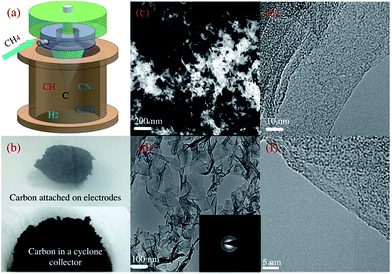
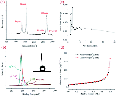
With high voltage exerted on the RGA reactor (Fig. 1a), CH4 was selectively and efficiently decomposed into H2, C2 hydrocarbons and carbon aerosol via interactions with versatile active species (Fig. S1 and S2 in the ESI†).21 Nest-like fluffy carbon was aggregated and deposited at the tip of the inner electrode (Fig. 1b, upper panel) due to the joint effect of swirling flow field and electromagnetic field, while most of carbon aerosol was purged out by N2 and collected in a cyclone separator (Fig. 1b, lower panel). In SEM images, loose and fuzzy nanostructure of carbon aerosol was observed, which was interweaved into porous channels (Fig. 1c). The morphologies were affected by CH4/N2 ratio, changing from stretched fuzzy flakes into branched granular particles with the enhancement of CH4 concentration (Fig. S4 in the ESI†). In TEM images (Fig. 1d), transparent and wrinkled carbon flakes with versatile edges structure were observed, which was mutually stacked and resulted into a crumple paper-like morphology.21,22 Relative strong 002, 10 and 11 reflection rings were indicted in SAED pattern (inset in Fig. 1d), implied relative high crystalline degree created with the effect of RGA plasma. Thin graphitic edges (Fig. 1e and f) were formed, consisting of 1–12 parallel folded layers with a uniform spacing of ∼0.35 nm.17 The growth rates of carbon aerosol were intimately related with the operating conditions such as gas flow rate, applied voltage and CH4 concentration (Fig. S4 in the ESI†). The maximum growth rate was about 100 mg min−1 in our series of experiments, and could be further enhanced by increasing applied voltage and gas flow rate.Raman spectrum was used to evaluate the graphitizing degree of the obtained carbon aerosol (Fig. 2a). Three distinguished feature peaks were observed at ∼1350 cm−1 (D peak), ∼1580 cm−1 (G peak) and ∼2670 cm−1 (2D peak), respectively.23 The presence of D peak, associated with structural defects or edges, was confirmed by versatile edges observed in SEM images (Fig. 1c).24 And the occurrence of sharp and intense G and 2D peaks, associated with high graphitized degree, implied the obtained carbon aerosol possessed a high sp2 structure. High crystalline quality of carbon aerosol was quantified by a low intensity ratio of D to G peak ID/IG (∼0.5), while a high intensity ratio of 2D to G peak I2D/IG (0.72) indicated the formation of few-layer carbon sheets, in consistence with edges structure in TEM images (Fig. 1f).
XPS survey was performed to investigate chemical component of carbon, which indicated a high C/O atomic ratio of ∼11 on the carbon surface (Fig. S6 in the ESI†). The asymmetric configuration of C1s peak (Fig. 2b) was deconvoluted into four peaks, corresponding to sp2 C![[double bond, length as m-dash]](https://www.rsc.org/images/entities/char_e001.gif) C at ∼284.5 eV (63.1%), sp3 C–C at ∼285.5 eV (17.8%), C–OH at ∼286.5 eV (5.7%) and O
C at ∼284.5 eV (63.1%), sp3 C–C at ∼285.5 eV (17.8%), C–OH at ∼286.5 eV (5.7%) and O![[double bond, length as m-dash]](https://www.rsc.org/images/entities/char_e001.gif) C–O– at ∼288.8 eV (13.3%). The high ratio of sp2 C
C–O– at ∼288.8 eV (13.3%). The high ratio of sp2 C![[double bond, length as m-dash]](https://www.rsc.org/images/entities/char_e001.gif) C facilitated the hydrophobic performance owing to the high degree of π electron delocalization conjugated system, while promoted the oleophilic performance by coupling sigma electron in oil with π electron on carbon surface.25 A high water contact angle of 141° was measured (inset in Fig. 2b). The porosity of carbon aerosol was assessed by nitrogen adsorption isotherm, which was identified as a type IV curve (Fig. 2d). The distribution of pore sizes (Fig. 2c) concentrated in a range of 2–5 nm, indicating a mesoporous structure formed in the plasma-generated carbon. The BET surface area was calculated to be about 248 m2 g−1, which was higher than carbon soot and part of commercial active carbon.26
C facilitated the hydrophobic performance owing to the high degree of π electron delocalization conjugated system, while promoted the oleophilic performance by coupling sigma electron in oil with π electron on carbon surface.25 A high water contact angle of 141° was measured (inset in Fig. 2b). The porosity of carbon aerosol was assessed by nitrogen adsorption isotherm, which was identified as a type IV curve (Fig. 2d). The distribution of pore sizes (Fig. 2c) concentrated in a range of 2–5 nm, indicating a mesoporous structure formed in the plasma-generated carbon. The BET surface area was calculated to be about 248 m2 g−1, which was higher than carbon soot and part of commercial active carbon.26
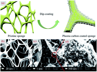
Carbon aerosol-based sponge was synthesized by a facile dip-coating method (Fig. 3a).1,11 Commercial sponge, as an excellent porous medium for oil and water adsorption, was widely used in daily kitchen cleaning.27 The pristine melamine sponge (Fig. 3b) possessed a distinguished 3D open-cell porous structure with pore sizes in a range of 100–150 μm. By dipping into carbon aerosol dispersion, previous clean and smooth skeletons of sponge were wrapped with dense bush-like aggregates of carbon aerosol (Fig. 3c). Due to strong van der Waals interaction, carbon aerosol was closely anchored on the sponge, resulting into a highly rough and porous surface layer. And the similar fluffy and porous morphology of carbon aerosol was maintained (Fig. 3d). Compared with the Raman spectrum of pure carbon aerosol, intense background noise was observed in the spectrum of coated sponge, with the blur and broad D and G peaks. In addition, a sharp peak at ∼975 cm−1, corresponding to the deformations of the trazine ring, was observed due to the melamine scaffolds (Fig. S7 in the ESI†).28 The mechanical strength and elasticity of sponges before and after the attachment of the carbon aerosol was also investigated. Both sponge of 1 cm2 could bear 4.9 kPa pressure without any deformation, which was much better than the result from other's work.15 By further increasing the pressure, the sponge presented the same deformation, which implied that mechanical strength and elasticity was mainly attributed to inter-connected skeleton of the pristine melamine sponge. According to Hooke's law, the elasticity coefficient of coated sponge was 980 N m−1 (Fig. S8 in the ESI†).
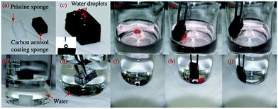
Owing to dipping-coating of high hydrophobic carbon aerosol, the previous white hydrophilic sponge was switched into a black hydrophobic one (Fig. 4a). The weight of carbon aerosol loading on the sponge could be easily controlled by the times of dip-coating cycles, with approximately 10% gain each time. For testing the variation of its wettability, the pristine sponge immediately sank into the bottom of a beaker, while carbon coated sponge floated on the water surface (Fig. 4b). And spherical shape of water droplets was statically maintained on the surface of coated sponge with the contact angle of 136° (Fig. 4c). The typical silver mirror-like phenomenon was observed when the aerosol carbon based sponge was forced into water (Fig. 4d), which was contributed to the enhancement of surface roughness of treated sponge. As we known, air was easily trapped in the cavities created by rough and porous surface structure, referring as non-wetting Cassie–Baxter surface, furthermore, the good hydrophobic property of attached carbon aerosol promoted to repel water completely.11,29 The adsorption performance of treated sponge was demonstrated by uptake of Sudan red dyed oil and chloroform (Fig. 4c–j). When the treated sponge contacted with oil droplets on water surface or chloroform droplets under water, the whole adsorption process completed within a few seconds. And no water was observed attached on the sponge after taking it out, which confirmed high adsorption selectivity and hydrophobicity of carbon aerosol based sponge prepared.
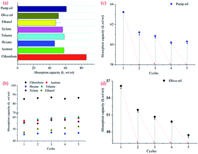
A variety of oil and organic solvent, as common water pollutant in our daily life and production, were used to quantitatively assess the adsorption capacity of our treated sponge (Fig. 5a). The adsorption capacities for ethanol, xylene, toluene, hexane and acetone were within a range of 46–58 times, while the adsorption capacities for pump oil and olive oil were 61.1 and 51.2 times, respectively. Among all the tested adsorbates, the treated sponge exhibited highest adsorption efficiency for chloroform with the adsorption capacity of about 86 times. It was thought the adsorption capacity was intimately related with physical properties of adsorbates, such as density, surface tension and hydrophobicity.2,30 In general, sponge coated with plasma-generated carbon aerosol achieved a high adsorption ability, which was attributed to special structure of the treated sponge. Firstly, 3D open-cell porous skeleton scaffolds of the pristine sponge provided large space for oil or solvent, furthermore, the induced capillary action helped to force the adsorbates sucked into pores spontaneously. In addition, the coating fluffy bush-like carbon aerosol also facilitated the adsorption of small organic molecules by affording extra cavities and increase of surface roughness.30 The recyclability of treated sponge was also significant for practical applications, which was evaluated by five cycle tests in present work. The used sponge could be easily recovered by evaporating or manual squeezing depended on the physical properties of adsorbates. When adsorbates were organic solvents, slight variations of absorption capacity were observed after 5 cycles, and even no weight loss was observed for the tested sponge (Fig. 5b). However, the absorption capacities decreased by approximately 10% after 5 cycles in uptake of pump oil and olive oil, which might attribute to loss of part carbon aerosol caused by squeezing process (Fig. 5c and d). But stilled an effective adsorption ability was retained if compared with counterpart coated with graphene.11
With the consideration of slight abscission of carbon aerosol from sponge in working condition, PDMS was used to further cement the carbon aerosol with the sponge (Fig. S9 in the ESI†). The porous skeleton scaffolds were wrapped by PDMS and carbon aerosol. It was observed previously coated carbon aerosol was embedded in a thin PDMS layer, while part of it remained protruding out, which caused the surface like the lotus leaf.31 The adsorption capacities for oil and different solvents seemed slightly changed with extra coating of PDMS, whereas a better recyclability of treated sponge was achieved during the adsorption of olive oil.
The comparison of various carbon based absorption materials were demonstrated (Table S1†), which indicated our plasma-generated carbon aerosol based spongy had a comparable performance in oil/organic solvents uptake with other types of absorption materials.
Conclusions
In summary, plasma-generated carbon aerosol was recycled as a cheap and reliable carbon source for fabrication of effective and recyclable sponge via an economic and scalable dip-coating approach. By coating with plasma-generated carbon aerosol, intrinsic wettability of the melamine sponge was drastically switched due to the increase of the surface roughness. In addition, the hydrophobicity and oleophilicity of treated sponge was further promoted with excellent properties of carbon aerosol generated by RGA plasma, such as stretch nanostructure, high surface area, abundant porosity and high crystallinity. The elasticity coefficient of coated sponge was as high as 980 N m−1. The saturated adsorption tests demonstrated treated sponge exhibited high absorption capacities for various oil and organic solvents, especially for high-density chemicals (86 times of its own weight for chloroform). And recovering of used sponge could be easily realized by simple evaporation or manual squeezing, while maintaining its high adsorption capacity after 5 cycles tests. PDMS could be used to enhance the adhesion of carbon aerosol on sponge surface without changing the adsorption capacity. The present work provided a new carbon source and carbon based adsorbents for potential applications in oil–water separation, organic volatile absorption and contaminants removal.Acknowledgements
This work is funded by National Natural Science Foundation of China (51576174).Notes and references
- Y. Gao, Y. S. Zhou, W. Xiong, M. Wang, L. Fan, H. Rabiee-Golgir, L. Jiang, W. Hou, X. Huang, L. Jiang, J. F. Silvain and Y. F. Lu, ACS Appl. Mater. Interfaces, 2014, 6, 5924 CAS.
- Y. Q. Li, Y. A. Samad, K. Polychronpoulou, S. M. Alhassan and K. Liao, ACS Sustainable Chem. Eng., 2014, 2, 1492 CrossRef CAS.
- S. Gupta and N. H. Tai, J. Mater. Chem. A, 2016, 4, 1550 CAS.
- J. Xie, W. Meng, D. Wu, Z. Zhang and H. Kong, J. Hazard. Mater., 2012, 231–232, 57 CrossRef CAS PubMed.
- R. Du, X. Gao, Q. Feng, Q. Zhao, P. Li, S. Deng, L. Shi and J. Zhang, Adv. Mater., 2016, 28, 936 CrossRef CAS PubMed.
- S. He, X. Cheng, Z. Li, X. Shi, H. Yang and H. Zhang, J. Mater. Sci., 2016, 51, 1292 CrossRef CAS.
- R. Gupta and G. U. Kulkarni, ChemSusChem, 2011, 4, 737 CrossRef CAS PubMed.
- H. X. Sun, A. Li, Z. Zhu, W. Liang, X. Zhao, P. La and W. Deng, ChemSusChem, 2013, 6, 1057 CrossRef CAS PubMed.
- R. Q. Long and R. T. Yang, J. Am. Chem. Soc., 2001, 123, 2058 CrossRef CAS PubMed.
- H. Sun, P. La, Z. Zhu, W. Liang, B. Yang, X. Zhao, C. Pei and A. Li, J. Mater. Sci., 2014, 49, 6855 CrossRef CAS.
- D. D. Nguyen, N. H. Tai, S. B. Lee and W. S. Kuo, Energy Environ. Sci., 2012, 5, 7908 CAS.
- H. Bi, X. Xie, K. Yin, Y. Zhou, S. Wan, L. He, F. Xu, F. Banhart, L. Sun and R. S. Ruoff, Adv. Funct. Mater., 2012, 22, 837 Search PubMed.
- R. W. Fu, B. Zheng, J. Liu, M. S. Dresselhaus, G. Dresselhaus, J. H. Satcher and T. E. Bauman, Adv. Funct. Mater., 2003, 13, 558 CrossRef CAS.
- C. F. Wang and S. J. Lin, ACS Appl. Mater. Interfaces, 2013, 5, 8861 CAS.
- H. Wang, E. Wang, Z. Liu, D. Gao, R. Yuan, L. Sun and Y. Zhu, J. Mater. Chem. A, 2015, 3, 266 CAS.
- J. Zhao, Q. Guo, X. Wang, H. Xie and Y. Chen, Colloids Surf., A, 2016, 488, 93–99 CrossRef CAS.
- X. Tu and J. C. Whitehead, Int. J. Hydrogen Energy, 2014, 39, 9658 CrossRef CAS.
- A. J. Wu, J. H. Yan, H. Zhang, M. Zhang, C. Du and X. Li, Int. J. Hydrogen Energy, 2014, 39, 17656 CrossRef CAS.
- A. J. Wu, H. Zhang, X. Li and S. Y. Lu, IEEE Trans. Plasma Sci., 2014, 42, 3560 CrossRef CAS.
- T. Zhang, L. Kong, M. Zhang, F. Qiu, J. Rong and J. Pan, RSC Adv., 2016, 6, 86510 RSC.
- T. Zielinski and J. Kijenski, Composites, Part A, 2005, 36, 467 CrossRef.
- M. M. Couranjou, M. Monthiux, J. G. Aguilar and L. Fulcheri, Carbon, 2009, 47, 2310 CrossRef.
- S. Karmakar, A. B. Nawale, N. P. Lalla, V. G. Sathe, S. K. Kolekar, V. L. Mathe, A. K. Das and S. V. Bhoraskar, Carbon, 2013, 55, 209 CrossRef CAS.
- Q. Zhou, Z. Zhao, Y. Zhang, B. Meng, A. Zhou and J. Qiu, Energy Fuels, 2012, 26, 5186 CrossRef CAS.
- S. Kabiri, D. N. H. Tran, T. Altalhi and D. Losic, Carbon, 2014, 80, 523 CrossRef CAS.
- X. J. Zhou, A. Buekens, X. D. Li, M. J. Ni and K. F. Cen, Chemosphere, 2016, 144, 1264 CrossRef CAS PubMed.
- X. Du, H. Y. Liu and Y. W. Mai, ACS Nano, 2016, 10, 453 CrossRef CAS PubMed.
- M. Scheepers, R. J. Meier, L. Markwort, J. M. Gelan, D. Vanderzande and B. Kip, Vib. Spectrosc., 1995, 9, 139 CrossRef CAS.
- I. A. Larmour, S. E. J. Bell and G. C. Sauders, Angew. Chem., Int. Ed., 2007, 46, 1710 CrossRef CAS PubMed.
- S. J. Yang, J. H. Kang, H. Jung, T. Kim and C. R. Park, J. Mater. Chem. A, 2013, 1, 9427 CAS.
- X. Zhang, Z. Li, K. Liu and L. Jiang, Adv. Funct. Mater., 2013, 23, 2881–2886 CrossRef CAS.
Footnote |
| † Electronic supplementary information (ESI) available. See DOI: 10.1039/c6ra26275a |
| This journal is © The Royal Society of Chemistry 2017 |

