DOI:
10.1039/C6RA26239B
(Paper)
RSC Adv., 2017,
7, 12534-12540
Electrochemical study on the corrosion behavior of Ti3SiC2 in 3.5% NaCl solution
Received
3rd November 2016
, Accepted 9th February 2017
First published on 21st February 2017
Abstract
As a newly developed conductive ceramic with wide application prospects, the electrochemical corrosion behavior of Ti3SiC2 in 3.5% NaCl solution was investigated by potentiodynamic polarization, potentiostatic polarization and electrochemical impedance spectroscopy. Commercially pure titanium (CP Ti) was selected for comparative, and cooperated with XRD, XPS, SEM, the passivation behavior, corrosion mechanism were clarified. Ti3SiC2 exhibits typical passivation characteristics and the corrosion resistance at self-corrosion potential is close to that of CP Ti. Silicon and titanium atoms nearby are selectively extracted resulting in a large amount carbon state in the passivation film, which mainly is composed of oxides and hydroxides related to Ti and Si. Lamellar microstructure and the differences between chemical bond of Ti–C and Ti–Si limits the passivation ability, resulting in a weaker passivation ability when compared to that of CP Ti.
Introduction
For electrochemical corrosion or even electro oxidation conditions, for example, in marine environment or wastewater treatment environment, titanium and its alloys are always mentioned and widely applied because of their excellent corrosion resistance due to a very stable oxide film forming on the metal surface.1 Titanium based electrodes, such as TiO2–RuO2–Ti,2–4 are also widely used in electrochemical engineering, such as in solar energy applications, chlorine production and electrolytic hydrogen production, because of its unique surface catalytic effect and stability. Recently, a new type of ternary layered conductive ceramic, Ti3SiC2, was found to be highly stable in concentrated hydrochloric acid solution and exhibited high catalytic activity for hydrogen evolution.5–8 Yanchun Zhou discovered that it is easy for Ti3SiC2 to be covered by in situ rutile TiO2 nanosheets with {010} crystal surface exposed, which indicates excellent surface catalytic activity.9 Moreover, Shufang Ren found that Ti3SiC2 exhibits excellent tribocorrosion resistance because of an in situ formed oxidation coating,10,11 which could be superior to titanium based electrode when facing fraction conditions. It could be concluded that Ti3SiC2 may have very broad application prospects in field of the ocean as substitutes of non-corrosive components or even adopted for sea water desalination,12,13 and electrolytic degradation of pollutants.14 However, mechanism of the corrosion of Ti3SiC2 in marine environment is still unclear.
As a bridge of ceramics and metals, Ti3SiC2, which belongs to Mn+1AXn (n = 1, 2, 3, wherein M is an early transition metal; A is an A group element; X is C or N), has gained vast attention and has been widely studied because of its combination of properties. Almost all studies on electrochemical corrosion of Ti3SiC2 were carried out by Barsoum and his co-workers and mostly focused on strong acid and base conditions.5–8 According to their reports, the high corrosion resistance of Ti3SiC2 could be attributed to the formation of a thin and passivation SiO2 based layer6 and in some circumstance exhibit superior corrosion resistance relative to pure titanium. According to the result of Ti3SiC2 corroded via hydrothermal oxidation15–17 and hot concentrated HCl,18 silicon atoms in the A site are prone to attack even though the material exhibits excellent stability. It was demonstrated that corrosion resistance was closely related to the nano-laminated crystal structure and the difference between A and M–X layers. That maybe indicated some difference when compared with valve metals such as titanium on passivation and corrosion mechanism. The present research suggests that Ti3SiC2 can potentially be used as an anodic and/or cathodic material in the chlor-alkali electrolysis industry;8 it is often inferred that they should be invulnerable to corrosion under relatively mild corrosive environments. However, this is possibly not always true in ocean environments. Understanding what happens during passivation and corrosion in NaCl solution is helpful to clarify the corrosion mechanism of MAX phase and it is important for its application in related environments, but this part has not been thoroughly investigated yet.
For further understanding on the possibility of Ti3SiC2 serving in the vast ocean, the anticorrosion properties of Ti3SiC2 were characterized by electrochemical methods, such as potentiodynamic polarization and electrochemical impedance spectroscopy (EIS). Moreover, the passivation process was clarified from the perspective of point defect model (PDM) by comparison to commercially pure titanium (CP Ti).
Experimental
Sample preparation
Bulk polycrystalline Ti3SiC2 samples used in this study were prepared by solid–liquid reaction and simultaneous in situ hot pressing process, which has been described elsewhere.19 Test coupons 10 mm × 10 mm × 3 mm in size were cut from the as-prepared bulk Ti3SiC2 samples using the electrical discharge method (EDM) and then sealed by epoxy with a copper wire connected on the back to form a working electrode. To obtain reproducible surfaces, test surfaces were first wet-ground with SiC emery papers to 2000 grit and then ultrasonically cleaned with acetone, followed by rinsing with distilled water before drying. Commercially pure titanium was chosen as comparative for further understanding of the corrosion and passivation behavior and also be sealed in epoxy except the test surface which was also wet-ground to 2000 grit and cleaned by ultrasonication in acetone.
Electrochemical measurements
Electrochemical tests were performed in a Zahner Zennium potentiostat/galvanostat (ZAHNER-Elektrlk GmbH &Co. KG, Germany) controlled by Thales Z2.22 software with a conventional three-electrode electrochemical cell full of 3.5% NaCl solution at room temperature. Platinum foil counter electrode and reference electrode, Ag/AgCl electrode (0.197 V vs. standard hydrogen electrode, SHE), were placed in the desired position. Potentiodynamic polarization measurements were carried out from −300 mV vs. open current potential (OCP) to breakdown with a scan rate of 0.333 mV s−1. The EIS (electrochemical impendence spectroscopy) signals were excited by an alternating current with amplitude of 5 mV and frequency changed from 100 kHz to 10 mHz. To achieve steady state conditions, EIS curves were obtained after immersion for 30 min or potentiostatic polarization for 12 hours at different potential.
Composition identification and morphology characterization
The composition of the passivation film that formed after potentiostatic polarization was identified by X-ray photoelectron spectroscopy (XPS). XPS was performed with an ESCALAB250 multifunctional surface analysis system (Thermo VG, America), which used Al Kα radiation (1486.6 eV) at a pass energy of 50 eV and resolution of 0.1 eV. The values of binding energies were aligned to carbon peak C 1s at 284.6 eV and details of Ti 2p, Si 2p, C 1s, O 1s and Al 2p were recorded. Zeiss scanning electron microscopy (SEM) was employed for surface morphology analyzing.
Results and discussion
Potentiodynamic polarization
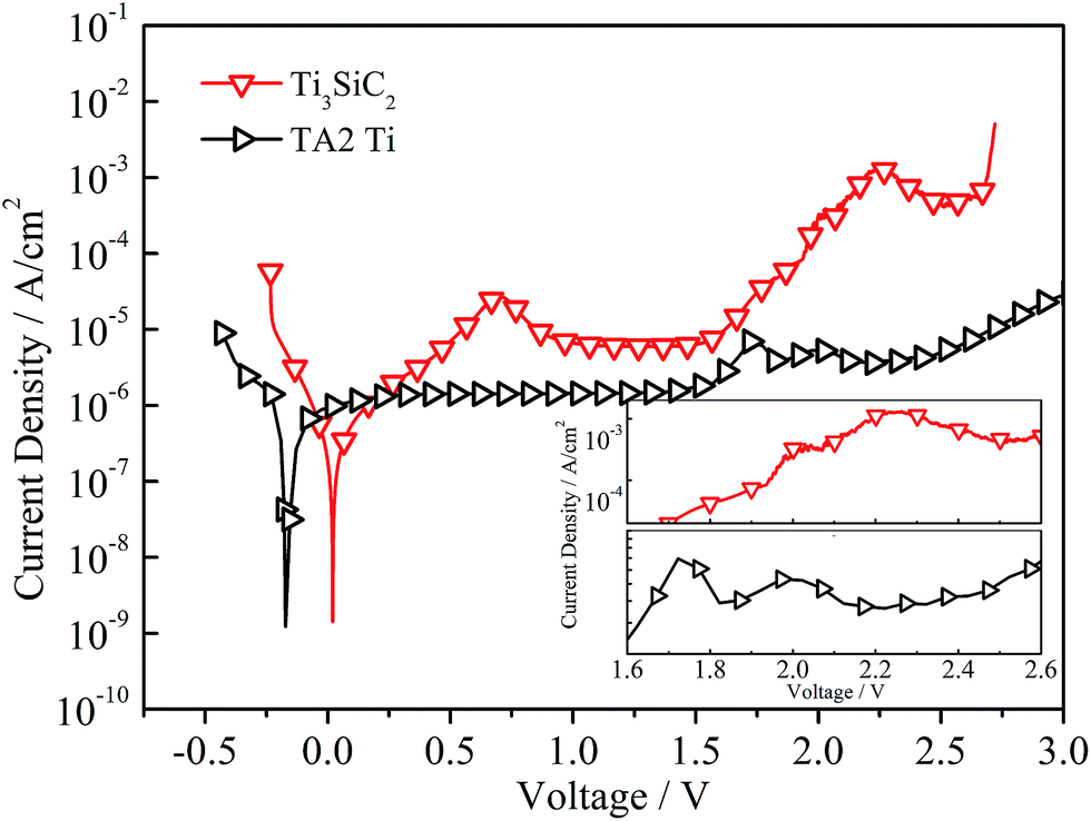
The potentiodynamic polarization curves of Ti3SiC2 in 3.5% NaCl solution after 30 min of immersion was presented in Fig. 1 and this material exhibits significant passivation characterization under anodic polarization. The anodic part of the polarization curves displayed an inflexion before 0.75 V and then decreased into the stable passivation region with a current density of about 6.67 × 10⁻⁶ A cm−2. The potentiodynamic polarization curve of commercially pure titanium (CP Ti) also demonstrated in Fig. 1 to be comparative and exhibited self-passivation characters clearly because of Ti(III) to Ti(IV) transformation could occurring at a very low polarization potential (0.1 V) and resulting in a stable titanium oxide (TiO2) passivation film.1,20 Electrochemical parameters such as self-corrosion potential (Ecorr), self-corrosion current density (icorr), passivation current density (ip), and breakdown potential (Eb) determined from the polarization curves are giving in Table 1. The anodic Tafel region of CP Ti is not well-defined and the self-corrosion current density could be substituted by stable passivation current density. Commercially pure titanium exhibits better passivation ability because of a lower current density (1.39 × 10⁻⁶ A cm−2). However, at free-corrosion potential, no significant difference in corrosion resistance could be found between Ti3SiC2 and CP Ti, as demonstrated in Fig. 1.
 |
| | Fig. 1 Potentiodynamic polarization curves of Ti3SiC2 and commercial titanium (CP Ti) in 3.5% NaCl solution at scanning rate of 0.333 mV s−1. | |
Table 1 Electrochemical parameters of Ti3SiC2 and CP Ti obtained from the polarization curves in 3.5% NaCl solution
| |
Ecorr (V) |
icorr (A cm−2) |
ip (A cm−2) |
Eb (V) |
| Ti3SiC2 |
−0.015 ± 0.02 |
(3.86 ± 0.02) × 10−7 |
(6.67 ± 0.41) × 10−6 |
2.695 ± 0.042 |
| CP Ti |
−0.157 ± 0.01 |
— |
(1.39 ± 0.22) × 10−6 |
— |
Different from most of the steel and chromium stainless steels, potentiodynamic polarization curves of Ti3SiC2 could extend to water electrolysis region in which a series of complicated redox reactions, as shown in eqn (1)–(5) for example, led to an electro oxidation solution environment.12–14,21 The anodic current density increased significantly fast after the potential was higher than 1.6 V, which could be attribute to both oxygen or chlorine devolution and electrochemical corrosion that occurred on the surface of the material. Details of the curves in the region from 1.6 V to 2.6 V are shown in the inset to Fig. 1. The peak of CP Ti located at 2.0 V could refer to solution oxidation (oxygen evolution), which also could be found for Ti3SiC2. With the participation of oxygen, the hill on the curve of Ti3SiC2 below 2.0 V very likely related to crystallization or structural change inside the films. The peak located at 0.75 V for Ti3SiC2 also indicated changes of passivation or corrosion process with the increasing of polarization potential. Although all the studies on the electrochemical corrosion of MAX phases were interpreted by traditional passivation theory like metals, the details of the corrosion and passivation mechanism must be different.
| | |
2H2O → O2 + 4H+ + 4e−, E0 = 1.229 V
| (1) |
| | |
2Cl− → Cl2 + 2e−, E0 = 1.36 V
| (2) |
| | |
Cl− + 3H2O → ClO3− + 6H+ + 6e−, E0 = 1.45 V
| (3) |
| | |
Cl− + H2O → HClO + H+ + 2e−, E0 = 1.49 V
| (4) |
| | |
Cl− + 4H2O → ClO4− + 8H+ + 8e−, E0 = 2.64 V
| (5) |
EIS measurement
For further investigation of the corrosion process and kinetics, EIS plots of Ti3SiC2 and commercially pure titanium in NaCl solution at OCP, and different polarization potentials were recorded and are displayed in Fig. 2. For all curves, the phase angle dropped to zero degrees at very high frequencies, indicating that impedance is dominated by solution area specific resistance and the phase remains close to −90° over a wide range of frequency indicating a near capacitive passivation film.22 With increasing polarization potential, the phase curves shifted to the right, indicating the thickening of passive film. The phase angle decreased towards lower values in the low frequency region, demonstrating that the impedance acts as a pure resistance of surface film. As Fig. 2a shows, the phase angle decreased to negative values as polarization potential was higher enough (2.4 V for example). The inductance characteristics could be caused by coupling of passivation film growth and dissolution23–26 as described elsewhere. Bode magnitude plots show a platform in the higher frequency region, which could be attributed to the electrolyte area specific resistance (solution resistance Rs), and the capacitive passivation film was reflected by a linear region with a slope of about −1.26 The wider range of platform in the curves of phase angle and higher magnitude modulus in low frequency indicated a more excellent passivation ability of CP titanium, which also could be clearly proofed by much greater capacitive arcs of CP Ti in Fig. 2b and d.
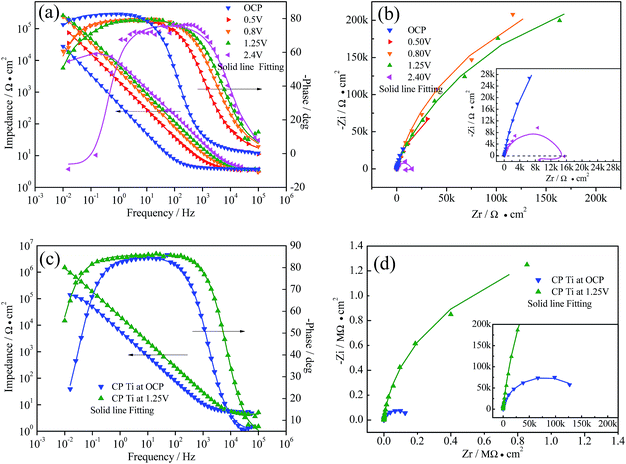 |
| | Fig. 2 Electrochemical impedance spectroscopy of Ti3SiC2 and CP Ti in 3.5% NaCl solution after immersion for 30 min (OCP) and potentiostatic polarization for 12 hours at different potential, (a) Bode plot of Ti3SiC2, (b) Nyquist plot of Ti3SC2, (c) Bode plot of CP Ti, and (d) Nyquist plot of CP Ti. | |
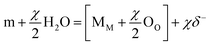
As point defect model (PDM) interpreted,27–29 the passivation films were indicated to possess a bi-layer structure. An inner defect oxide barrier layer grows into the matrix and an outer porous layer forms by precipitations produced by reactions between cations transmitted through the barrier layer and species (water, particularly OH− in current situation) in the environment. The passivation process could be described by eqn (6) and (7), which explain film growth and matrix dissolution respectively:
| |
 | (6) |
| | |
m → Mδ+ (aq) + Vm + δe−
| (7) |
where m is the atoms in matrix, M
δ+ (aq) is cation in outer layer/solution interface, M
M is the cation in the cation site on the cation sublattice, O
O is the oxide ion in the anion site on the anion sublattice, and V
m is the matrix atoms vacancy.
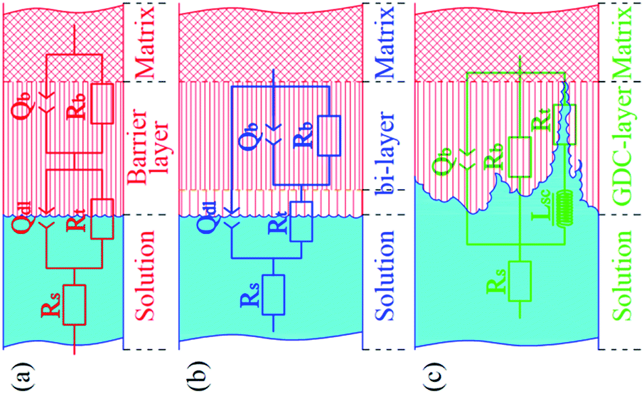
Based on the point defect model (PDM) and the character of the EIS plots, three two time constant equivalent circuits, shown in Fig. 3, were chosen for fitting the experimental data. For the EIS data of Ti3SiC2 at OCP, 0.5 V and 0.8 V, Rs(QdlRt)(QblRb), as shown in Fig. 3a, could fit the raw data very well, which indicated that the outer porous layer of the passivation film was nearly negligible, so did the plots of CP Ti at open current potential. With the increase in polarization potential, a new two time constants EEC as shown in Fig. 3b must be adopted for Ti3SiC2 and CP Ti at 1.25 V, which indicates a formation of an outer layer due to the diffusion of cations through the inner barrier layer under higher potential. EIS spectra of Ti3SiC2 at 2.4 V could be characterized by a capacitive loop, followed by an inductive loop in lower frequency region. This type of behavior can be interpreted using ESS as shown in Fig. 3c, which has widely been used to describe EIS spectra which are related to the film dissolution–passivation of value metals in their passive regions.23–26 Lsc in Fig. 3c is associated with the film dissolution or the negative surface charge. The symbol Q signifies the possibility of a non-ideal capacitance (CPE, constant phase element). The impedance of the CPE is given by as follows:
| | |
Q = ZCPE(w) = [C(jw)n]−1
| (8) |
where for
n = 1, the
Q element reduces to a capacitor with the capacitance
C and for
n = 0, to a simple resistor. The values of the fitting parameters for the equivalent circuit under different conditions are presented in
Table 2.
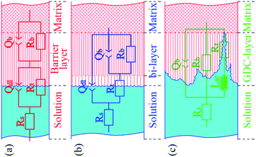 |
| | Fig. 3 Equivalent circuit (ECC) used for fitting the experimental data, (a) schematic and ECC used for nearly monolayer passivation film. In situation of Ti3SiC2 at OCP, 0.5 V and 0.8 V and CP Ti at OCP, (b) schematic and ECC used for bi-layer structure. In situation of Ti3SiC2 and CP Ti at 1.25 V, (c) schematic and ECC used for film growth-dissolution-coupling (GDC) situation, Ti3SiC2 at 2.4 V. Rs represent for solution resistance, Qdl and Rt are the electrical double-layer capacitor and charge transfer resistance, and Qb and Rb represent the barrier layer capacitor and resistance. | |
Table 2 Values of fitted parameters of the equivalent circuit under different conditions of Ti3SiC2 and CP Ti in 3.5% NaCl solution
| |
Rs (Ω cm2) |
Qdl (10−4 F cm−2) |
n |
Lsc (104 H cm2) |
Rt (Ω cm2) |
Qb (10−5 F cm−2) |
n |
Rb (104 Ω cm2) |
χ2 |
| Ti3SiC2 |
| OCP |
3.754 |
33.7 |
0.677 |
|
0.50 |
4.41 |
0.925 |
21.85 |
2.05 × 10⁻⁴ |
| 0.5 V |
3.14 |
19.77 |
0.609 |
|
1.49 |
9.34 |
0.881 |
28.7 |
2.92 × 10⁻⁴ |
| 0.8 V |
3.16 |
11.88 |
0.615 |
|
1.59 |
4.18 |
0.884 |
63.3 |
6.08 × 10⁻⁴ |
| 1.25 V |
3.34 |
28.0 |
0.90 |
— |
7.67 × 10⁴ |
1.17 |
0.900 |
30.9 |
2.94 × 10⁻³ |
| 2.4 V |
3.63 |
— |
— |
3.38 |
4.49 × 10⁴ |
2.19 |
0.855 |
5.46 |
6.04 × 10⁻³ |
![[thin space (1/6-em)]](https://www.rsc.org/images/entities/char_2009.gif) |
| CP titanium |
| OCP |
4.87 |
0.06 |
0.979 |
— |
1.38 |
2.278 |
0.935 |
16.3 |
2.84 × 10⁻⁴ |
| 1.25 V |
4.36 |
0.08 |
0.959 |
— |
5.93 × 10⁵ |
0.08 |
0.953 |
224.7 |
3.05 × 10⁻³ |
Corresponding with the polarization curves, the anti-corrosion abilities reflected by Rp (which could simply be regarded as the combination of Rb and Rt in present situation) demonstrated a weaker passivation ability of Ti3SiC2 compared with CP titanium. As indicated by fitting parameters, the CP Ti has a slightly better corrosion resistance, which corresponds with the result of Barsoum30 even though there was no further explanation. The greater Rt at 1.25 V could attribute to the resistance of charge transfer caused by thicker porous outer layer. As polarization potential increased, the passivation film changed from nearly monolayer structure to a clear bi-layer structure, and the Rp decreased in stable passivation region (0.51 MΩ cm2 vs. 0.63 MΩ cm2) which was contrary to valve metals.26,31 Although nearly all researchers attribute the high corrosion resistance of Ti3SiC2 to the passivation, the result of the EIS analysis indicates that the corrosion and/or passivation mechanism was different to the traditional metals.
Surface chemistry of polarized surface
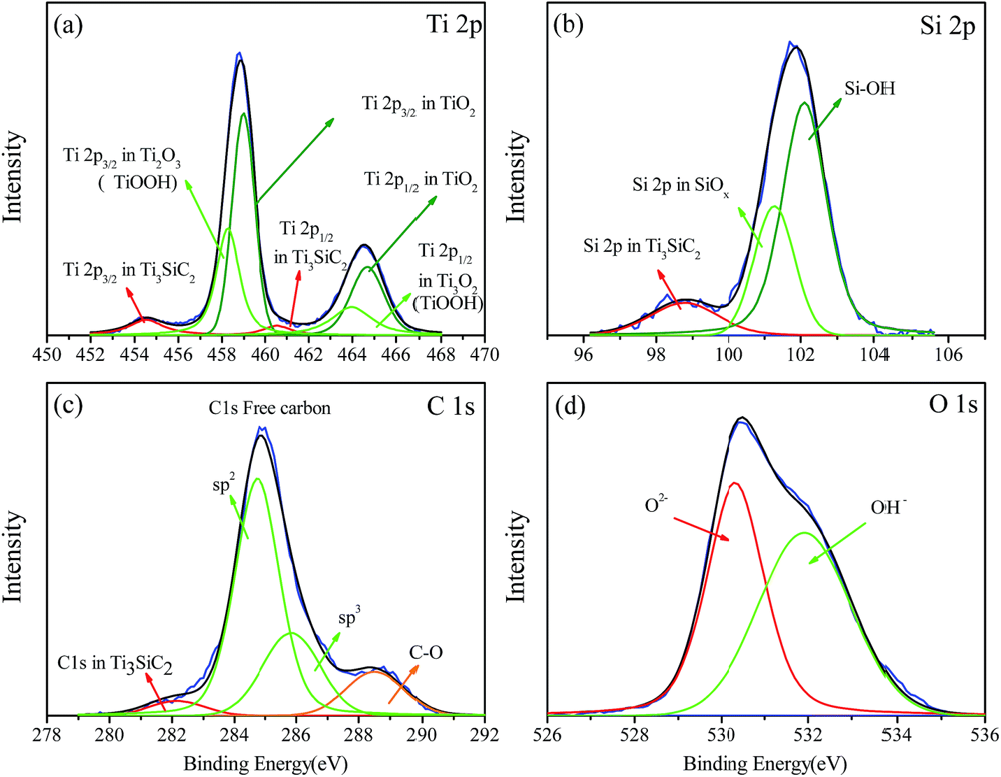
In order to clarify the passivation mechanism of Ti3SiC2, chemical compositions of passivised surface after potentiostatic polarization at 1.25 V for 12 h were investigated by XPS, as shown in Fig. 4. The passivation films are mostly composed of oxide and hydroxide and could be observed by deconvoluted spectra of O 1s in Fig. 4c. Coincidence with abound researches1,20 on the composition of passivation films on the surface of titanium contain alloys including CP titanium, titanium(IV) oxide (TiO2, the Ti 2p3/2 peak is locked at nearly 459.0 eV), is the major component of the titanium contain compound as shown in Fig. 4a. Another peak located at 457.6 eV was attributed to sub-oxide and the chemical state of titanium in Ti3SiC2 could also be detected at about 454.5 eV. As demonstrated in Fig. 4b, the chemical state of silicon at the surface was complex and could be grossly divided into two groups, metastable oxide and hydroxide, which indicated that silicon atoms were not the dominant electron source during electrochemical corrosion. Spectra of C 1s at the surface are shown in Fig. 4c. The main peaks appeared at 285.6 eV with a full width at half maximum (FWHM) of 1.9 eV, which considerably exceeds that of graphite (1.3 eV) and diamond (1.4 eV).32–34 The asymmetric broadening to higher binding energy and the small shoulder together with high FWHM suggest that at least two components contribute to this peak. Zhang et al.17 also found that the carbon exists as sp2 in 284.3 eV and sp3 in 285.4 eV in the surface of Ti3SiC2 after hydrothermal oxidation because of selective oxidative extraction of titanium and silicon. Photoelectron spectrum signals of C 1s come from Ti3SiC2 also could be detected and another peak at 287.3 eV possibly comes from C–O bonding formed during corrosion. The elemental content of the surface can be seen in Table 3. The much lower ratio of Ti/C and Si/C compared with Ti3SiC2 indicates that most Ti and Si atoms in the lattice were selectively corroded into solution and carbon resided in the form of elementary substance. Moreover, titanium and silicon were detected in solution by inductively coupled plasma (ICP). The silicon content was nearly two orders of magnitude higher than that of titanium although the flame of chlorine has some effect on the test results. The result of a first principles calculation35–37 indicated that the chemical bond between Si and Ti–C layer was very weak and the electrical conductivity could be mostly attributed to 3d electron of titanium atoms adjacent to silicon. Therefore, most electrons in the loop were provided by titanium and silicon easily diffused into the solution during corrosion.
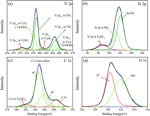 |
| | Fig. 4 Deconvoluted XPS spectra recorded at the layer formed on Ti3SiC2 potentiostatic polarized at 1.25 V in 3.5% NaCl solution for 12 hours, (a) Ti 2p, (b) Si 2p, (c) C 1s, (d) O 1s. | |
Table 3 Element content (atom percentages) on the surface of Ti3SiC2 after potentiostatic polarized at 1.25 V for 12 hours in 3.5% NaCl solution recorded by XPS
| |
Ti |
Si |
Al |
C |
O |
| Ti3SiC2 |
7.93 |
5.07 |
|
46.71 |
40.28 |
Corrosion morphology and corrosion mechanism analysis
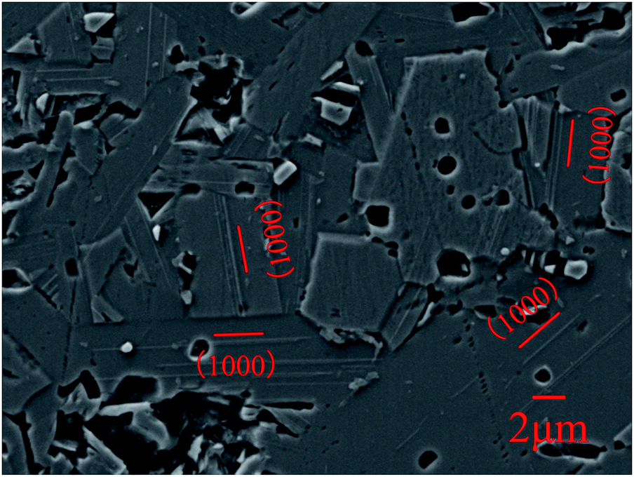
For understanding of the effect of special lamellar microstructure on the corrosion, Ti3SiC2 was etched by aqua as pretreatment and then potentiostatically polarized at 2.4 V. The corrosion morphologies are shown in Fig. 5. Except for some holes caused by shedding of small grains, a series of parallel ridges were distributed along the (1000) lattice plane. Limited by the resolution of EDS, the difference between the ridges and parts near by could not be distinguished well. Nevertheless, according to the perspective of PDM as discussed before, silicon and titanium atoms nearby are more likely diffused outward and the ridges should be silicon and titanium based oxide. On the other hand, the distribution regularity of ridges is coincidence with Si layer in the crystal lattice of Ti3SiC2. A similar phenomenon was also reported by Borsoum and Jovic when they studied the corrosion behavior of Ti3SiC2 in several common acids.5
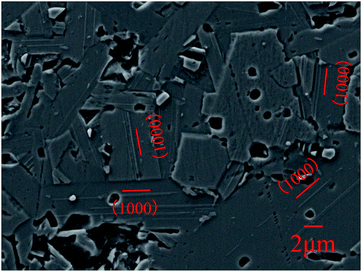 |
| | Fig. 5 SEM morphology micrographs of Ti3SiC2 etched by aqua and then followed by potentiostatic polarization in 3.5% NaCl solution at 2.4 V. | |
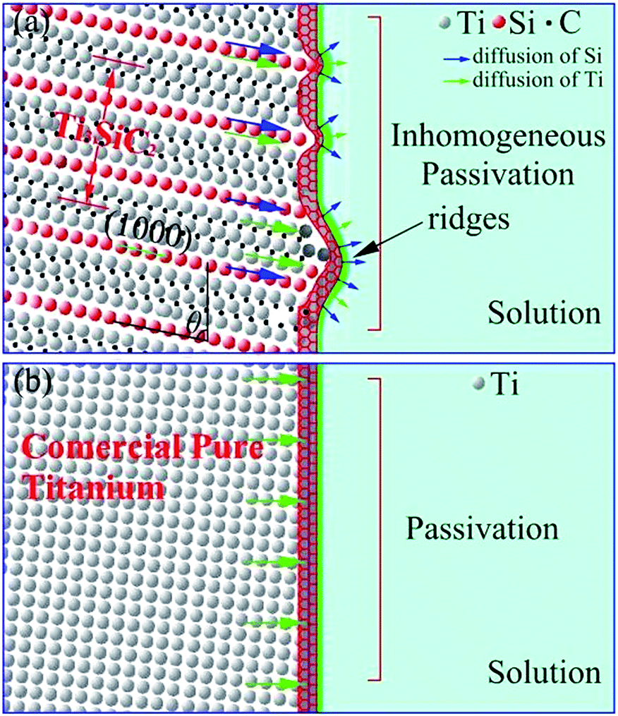
The corrosion/passivation mechanism could be sketched in Fig. 6 that layered crystal structure and weaker chemical bond between Si and Ti–C layer made silicon atoms are more likely diffused outward which promoted the reaction (7). Silicon and titanium inhomogeneous diffusion reduced efficiency of passivation films generation and a great deal of silicon and titanium atoms loss into solution and which could be due to the increasing of polarization potential. Under lower potential, the reaction (6) dominates and the modulus value increased from OCP to 0.8 V. The reaction (7) gradually taking over higher than 0.8 V and film structures tend to obvious bi-layer cause by outward diffusion. So the modulus value decreased slightly at 1.25 V and even exhibited inductive reactance at 2.4 V. The peak near 0.75 V in Fig. 1 could also be attributed to the relative strength of reactions (6) and (7). Moreover, as has been widely studied, there is a great gap on the ability to provide electronics between MX and A layer, which could lead to a micro galvanic cell in the crystal of MAX phases. Cooperated with halogen and strong surface electric field, Ti3SiC2 showed a clear breakdown potential, whereas CP Ti did not.
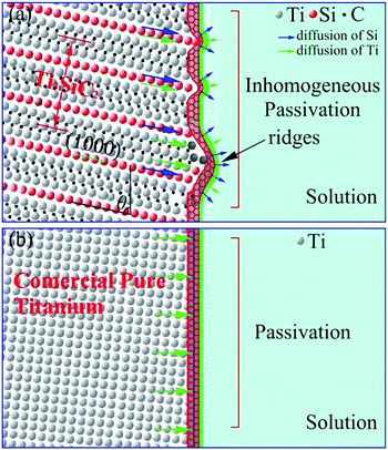 |
| | Fig. 6 The Schematic of passivation in 3.5% NaCl solution and the difference, (a) schematic of Ti3SiC2, (b) schematic diagram of CP titanium. | |
On the contrary, titanium atoms in CP Ti diffused uniformly into the barrier layer enhanced the protection of the passivation film as shown in Fig. 6b. That is why CP titanium exhibited better passivation behavior, and the outer layer at 1.25 V could be attributed to the reversible dissolution–precipitation reaction of the inner barrier layer.
Conclusions
The electrochemical corrosion properties of Ti3SiC2 were investigated and the corrosion and/or passivation mechanism were clarified by compared with typical valve metal CP titanium.
The special lamellar microstructure provides a convenient diffusion path for silicon, which result in lower passivation efficiency for atoms diffused into the barrier layer. Compared to CP titanium, Ti3SiC2 exhibited excellent corrosion but had no significant advantages in corrosion resistance at open current potential. Also, the passivation ability was lower than CP Ti.
Acknowledgements
This study was support by the National Natural Science Foundation of China (Grants No. 51201131, 91326102 and 51532009), Science and Technology Program of Shaanxi Province, China (2013KJXX-42), and the Science and Technology Development Foundation of China Academy of Engineering Physics (Grant No. 2013A0301012). Haibin Zhang is grateful to the foundation by the Recruitment Program of Global Youth Experts and the Youth Hundred Talents Project of Sichuan Province.
References
- Y. Z. Huang and D. J. Blackwood, Electrochim. Acta, 2005, 51, 1099 CrossRef CAS.
- M. T. Colomer and M. J. Velasco, J. Eur. Ceram. Soc., 2007, 27, 2369 CrossRef CAS.
- R. Y. Chen, V. Trieu, H. Natter and R. Hempelmann, US Pat., 0 308 939 2011, 2011.
- J. C. Wright, A. S. Michaels and A. J. Appleby, AIChE J., 1986, 32, 1450 CrossRef CAS.
- J. Travaglini, M. W. Barsoum and V. Jovic, Corros. Sci., 2003, 45, 1313 CrossRef CAS.
- V. D. Jovic and M. W. Barsoum, J. Electrochem. Soc., 2004, 151, B71 CrossRef CAS.
- V. D. Jovic, B. M. Jovic and M. W. Barsoum, Corros. Sci., 2006, 48, 4274 CrossRef CAS.
- V. D. Jovic and M. W. Barsoum, US Pat., 7 001 494, 2006.
- J. L. Gai, J. X. Chen and Y. C. Zhou, Scr. Mater., 2015, 108, 92 CrossRef CAS.
- S. F. Ren, J. H. Meng and J. B. Wang, Wear, 2010, 269, 50 CrossRef CAS.
- S. F. Ren, J. H. Meng and J. B. Wang, Wear, 2012, 274–275, 8 CrossRef CAS.
- Q. Zhang, S. Z. Yi and S. Y. Wang, Desalin. Water Treat., 2013, 51, 3858 CrossRef CAS.
- C. P Feng, K. Suzuki and S. Y. Zhao, Bioresour. Technol., 2004, 94, 21 CrossRef PubMed.
- G. H. Chen, Sep. Purif. Technol., 2004, 38, 11 CrossRef CAS.
- H. B. Zhang, K. G. Nickel and Y. C. Zhou, Scr. Mater., 2008, 59, 746 CrossRef CAS.
- H. B. Zhanga, K. G. Nickel and Y. C. Zhou, J. Eur. Ceram. Soc., 2009, 29, 2097 CrossRef.
- H. B. Zhang, V. Presser and K. G. Nickel, J. Am. Ceram. Soc., 2010, 93, 1148 CrossRef CAS.
- J. Xie, X. H. Wang and Y. C. Zhou, Corros. Sci., 2012, 60, 129 CrossRef CAS.
- Y. C. Zhou, Z. M. Sun, S. Q. Chen and Y. Zhang, Mater. Res. Innovations, 1998, 2–3, 142 CrossRef.
- E. Pelaez-Abellana and L. Rocha-Sousab, Corros. Sci., 2007, 49, 1645 CrossRef.
- H. Bergmann and S. Koparal, Electrochim. Acta, 2005, 50, 5218 CrossRef CAS.
- J. Liu, A. Alfantazi and E. Asselin, Appl. Surf. Sci., 2013, 283, 705 CrossRef CAS.
- M. Bojinov, J. Solid State Electrochem., 1997, 1, 161 CrossRef CAS.
- M. Bojinov, Electrochim. Acta, 1997, 42, 3489 CrossRef CAS.
- M. Bojinov, I. Betova and G. Fabricius, Corros. Sci., 1999, 41, 1557 CrossRef CAS.
- M. Bojinov, S. Cattarin and M. Musiani, Electrochim. Acta, 2003, 48, 4107 CrossRef CAS.
- D. Ellerbrock and D. D. Macdonald, J. Solid State Electrochem., 2014, 18, 1485 CrossRef CAS.
- D. D. Macdonald, Russ. J. Electrochem., 2012, 48, 235 CrossRef CAS.
- D. D. Macdonald, Pure Appl. Chem., 1999, 71, 951 CrossRef CAS.
- S. M. EL-Raghy, A. F. Waheed and M. W. Barsoum, J. Mater. Sci. Lett., 1999, 18, 519 CrossRef CAS.
- M. Bojinov, I. Betova and G. Fabricius, Corros. Sci., 1999, 41, 1557 CrossRef CAS.
- T. Y. Leung, W.
F. Man, P. K. Lim, W. C. Chan, F. Gaspari and S. Zukotynski, J. Non-Cryst. Solids, 1999, 254, 156 CrossRef CAS.
- J. Filik, P. W. May, S. R. J. Pearce, R. K. Wild and K. R. Hallam, Diamond Relat. Mater., 2003, 12, 974 CrossRef CAS.
- X. B. Yan, T. Xu, G. Chen, S. G. Yang and H. W. Liu, Appl. Surf. Sci., 2004, 236, 328 CrossRef CAS.
- E. H. Kisi, J. A. A. Crossley and M. W. Barsoum, J. Phys. Chem. Solids, 1998, 59, 1437 CrossRef CAS.
- N. I. Medvedeva, Phys. Rev. B: Condens. Matter Mater. Phys., 1998, 58, 16042 CrossRef CAS.
- Z. M. Sun and Y. C. Zhou, Phys. Rev. B: Condens. Matter Mater. Phys., 1999, 60, 1441 CrossRef CAS.
|
| This journal is © The Royal Society of Chemistry 2017 |
Click here to see how this site uses Cookies. View our privacy policy here. 
 Open Access Article
 This Open Access Article is licensed under a Creative Commons Attribution-Non Commercial 3.0 Unported Licence
 a,
Rui Wangb,
Chen Chenb,
Haibin Zhang*b and
Guojun Zhangc
a,
Rui Wangb,
Chen Chenb,
Haibin Zhang*b and
Guojun Zhangc