
 Open Access Article
 This Open Access Article is licensed under a Creative Commons Attribution-Non Commercial 3.0 Unported Licence
Impact of ferrocene on the nanostructure and functional groups of soot in a propane/oxygen diffusion flame
Chao Hua,
Wenzhi Li *a,
Qizhao Lin*a,
Xusheng Zhengb,
Haibin Panb and
Qifu Huanga
*a,
Qizhao Lin*a,
Xusheng Zhengb,
Haibin Panb and
Qifu Huanga
aDepartment of Thermal Science and Energy Engineering, University of Science and Technology of China, Jinzhai Road, Hefei 230026, People's Republic of China. E-mail: liwenzhi@ustc.edu.cn; qlin@ustc.edu.cn; Fax: + 86 5516 3600786; Tel: + 86 5516 3600786
bNational Synchrotron Radiation Laboratory, University of Science and Technology of China, Jinzhai Road, Hefei 230026, People's Republic of China
First published on 17th January 2017
Abstract
This study presents the effect of ferrocene ((C5H5)2Fe) on the soot oxidation activity by influencing the nanostructure and molecular structure of soot. Soot particles were obtained at different heights from propane/oxygen flames without and with ferrocene added to the fuel, respectively. The fringe properties of soot were compared using the skeleton images extracted from the high-resolution transmission electron microscopy images of soot particles. Near-edge X-ray absorption fine structure spectroscopy was used to characterize the carbon chemistry of soot particles. It was found that ferrocene reduced the degree of graphitization of soot by changing its fringe length, tortuosity, and separation distance, and these effects were much more obvious near the flame terminus. These changes may be related to ferrocene dropping the flame temperature there. Fe from (C5H5)2Fe reacting with OH and O radicals decreased the oxygen-containing functional groups of soot and affected its aromatic structure after the addition of (C5H5)2Fe to the flame. The inner cores of soot particles were also much bigger due to partial oxidation. Thermogravimetric analysis revealed that ferrocene promoted the soot oxidation at low temperatures.
1. Introduction
Particle matter (PM) is a part of air pollution that consists of dust, smog components, liquid droplets containing acids, and soot particles.1 PM usually contributes to serious lung, heart, and cerebrovascular diseases and causes global warming.2 Soot particles, from the combustion of fossil fuels, compose a significant portion of PM. It is necessary to reduce the harmful soot emissions from the combustion processes. One of the promising ways of reducing soot particles is the utilization of so-called fuel borne catalysts (FBCs).2 Metal-based additives, including cerium, platinum, iron, manganese, calcium, and copper, have been studied as FBCs to reduce the soot emissions for hydrocarbon fuels.3Among these FBCs, ferrocene is a well-known flame quencher with soot-suppressing properties and is cheap, heat stable, relatively non-toxic, and easy to handle.4,5 When added to the diesel fuel, ferrocene facilitates soot oxidation in particle filters and effectively reduces the overall soot yields through burnout.6 Soot particles with iron oxide were efficiently oxidized via reactions such as: C + FexOy → FexOy−1 + CO.7 In Artur Braun's study, the emerging soot from diesel with ferrocene carried aliphatic structures at different engine speeds.8 The effects of ferrocene on the soot formation and growth were also studied in ethylene and propene flames.4,7 Compared with an undoped ethylene diffusion flame, the addition of ferrocene caused soot surface changes in both primaries and aggregates, resulting in less compact structures and less smooth surfaces.7
The physical structure is a key factor in influencing the oxidative reactivity of the soot particles. For example, the morphology of soot particles (internal structure, shape, and size) affects soot oxidation, whereas concentrically oriented and larger crystallites decrease the soot reactivity.9 However, it should be noted that different soot nanostructural properties, particularly its degree of graphitization, have an important influence on the oxidative reactivity of soot.
Although carbon nanostructures are usually studied by Raman spectroscopy and X-ray diffraction, neither of these two techniques indicate the configurations of the graphene layers of soot.10 High-resolution transmission electron microscopy (HRTEM), as a unique tool, can compensate for this limitation and visualize the carbon lattice fringes.11 These fringes are usually used to quantify nanostructures with respect to the orientation of carbon lamellae, fringe length, tortuosity, and separation.12 The degree of graphitization of soot particles is characterized by these parameters: with increasing graphitization, fringes become longer and more rectilinear, and the fringe separation is reduced.13 The fringes of graphene are flat and consist of 6-membered rings; however, the 5- and 7-membered rings in soot particles result in their fringe tortuosity.14 The bent graphene layers are also characterized in terms of the sp2/sp3 ratio, as a parameter to distinguish between a more or less graphitic character.15 Near-edge X-ray absorption fine structure (NEXAFS) spectroscopy is especially suitable for the characterization of these complex heterogeneous samples, because absorption spectra are related to the local bonding environment of atoms.16
In the meantime, surface functional groups, especially oxygen-containing groups, also influence soot oxidation and should be taken into consideration. The changes in these groups in soot can be detected by NEXAFS spectroscopy.
NEXAFS spectroscopy is a technique that involves the transitions of electrons excited by an incident X-ray photon from an occupied molecular orbital to partially filled and empty molecular orbitals.17,18 In particular, the peak at 285 eV stems from excitations from the 1s level to empty π* states, while the peak for higher energy losses around 292 eV results from excitations from the 1s level to empty σ* states.19,20 The method depends on the hypothesis that the intensities of the σ* and π* peaks are proportional to the densities of the σ and π states in the carbon sample.15 The intensity ratio of the π* peak to the σ* peak is frequently used to quantify the degree of graphitization of carbonaceous materials. The peaks between 286 and 289 eV are typically attributed to oxygen-containing functional groups.
In our previous work, we studied the effects of ferrocene on flame temperature and polycyclic aromatic hydrocarbons (PAHs), and found that the reactions between ferrocene and oxygen dropped the flame temperature and restrained the growth of PAHs.21 When the volume fraction of ferrocene in the fuel was 0.2%, there were about 100 K decreases in temperature near the flame terminus. Soot particles may possess very different nanostructures, depending upon the fuel and temperature of combustion.22 Vander Wal and Tomasek presented evidence showing that the effect of temperature on soot nanostructure mainly arises from the rate of increase of temperature.23 Temperature affects both the gas-phase species added to the soot surface and the way in which they add.7,23 The functional groups on soot are also related to the flame temperature. Cain et al. concluded that increases in flame temperature result in high contents of non-aromatic functionalities in soot from ethylene/oxygen flames.24
After the addition of ferrocene, primary particle sizes of soot are almost invariant, the agglomerates become smaller, and the crystallite size of soot decreases.25,26 The effects of ferrocene on flame temperature have been studied in our previous work.21 However, the study of the influence of ferrocene on soot nanostructure and functional groups, and their relationships with flame temperature and soot oxidation is limited. The main aim of the current study is to investigate how ferrocene affects the oxidative reactivity of soot by changing its nanostructural properties, particularly its degree of graphitization, and its surface oxygen-containing functional groups, and to find out how these changes relate to the effect of ferrocene on flame temperature.
Within the framework of this paper, the impact of ferrocene on the oxidation activity of soot particles was investigated at different flame heights in a propane/oxygen diffusion flame. As a key factor influencing the soot oxidation, the nanostructure of soot was characterized by HRTEM with three parameters. The effect of ferrocene on the functional groups of soot particles was studied by NEXAFS. It was testified via thermogravimetric analysis (TGA) that ferrocene affected soot oxidation by changing its nanostructure and molecular structure.
2. Experimental section
2.1. Experimental apparatus
In this study, soot particles were obtained from a propane/oxygen diffusion flame with or without ferrocene added to the fuel. Fig. 1 shows a schematic of the soot generation and sampling system. A thermophoretic sampling technique was used to extract soot particles for subsequent analyses. A quartz tube was placed horizontally in the flame at different heights above the burner (HAB). By passing cold water through the tube, soot particles could be trapped on its outer surface. The inner diameter of the tube was 6 mm and its outer diameter was 10 mm. The residence time of the tube in the flame was less than 1 s. During the experiments, in order to ensure that flames had the same structure, the equivalent ratio of propane/oxygen in the flame was kept at 2.52, and the oxygen flow rate (2.18 L min−1) and the propane flow rate (1.10 L min−1) were held constant by mass flow controllers. The length of the flames, with or without ferrocene added to the fuel, was kept at 16 cm, which was measured by a ruler with a minimum scale of 1 mm next to the flame. Considering the reactions between oxygen and ferrocene, we used oxygen instead of air as oxidant in the study.21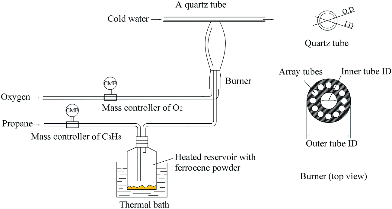 | ||
| Fig. 1 Schematic of soot particle generation and sampling system. | ||
The temperature profile of these flames, with or without ferrocene, was measured by primary-color pyrometry in our previous work.21 We found that there was no obvious difference between flames with and without ferrocene, for flames with heights under 8 cm. However, when the volume fraction of ferrocene in the mixture was 0.2%, there were about 80 K decreases in temperature between 8 and 12 cm flame heights, and 100 K decreases between 12 and 16 cm flame heights. Ferrocene was found to reduce the flame temperature significantly near the flame terminus. So, during the experiments, samples were collected at heights of 7 and 14 cm from the flames with and without ferrocene.
Ferrocene was added to the flame by passing the stream of propane through a reservoir containing ferrocene powder, according to ref. 7. The reservoir was placed in a hot-water bath at a temperature of 363.2 K to heat the ferrocene and increase its vapor pressure. Ferrocene was sublimed when heated, and its vapor pressure is given as follows:  , where R = 8.314 J mol−1 K−1, θ = 317.20 K, Psv is the vapor pressure, and T is the temperature.7 At 363.2 K, the evaluated vapor pressure is 204 Pa, and the percentage volume fraction of ferrocene in the mixture is 0.2%. The diameters of the inner tube and outer tube are 2 mm and 12 mm, respectively, and the diameters of the 12 array tubes are 1.5 mm.
2.2. Analysis methods
![[thin space (1/6-em)]](https://www.rsc.org/images/entities/char_2009.gif) 000× magnification. The post-processing of these images was conducted using custom algorithms interfacing with Matlab software, as described in ref. 10 and 27. All these images were processed by a procedure involving the separate steps of conducting negative transformations, selecting the regions of interest (ROIs), improving contrast, applying a Gaussian low-pass filter, top-hat transformation and binarization, skeletonizing elements, breaking triple or quadruple joints, and ruling out small artifacts. After application of the image processing, three parameters, including fringe length, fringe tortuosity, and fringe separation were quantified to describe the nanostructures of soot particles using processing software Image-Pro Plus 6.0 (Media Cybernetics), from these skeleton images.
000× magnification. The post-processing of these images was conducted using custom algorithms interfacing with Matlab software, as described in ref. 10 and 27. All these images were processed by a procedure involving the separate steps of conducting negative transformations, selecting the regions of interest (ROIs), improving contrast, applying a Gaussian low-pass filter, top-hat transformation and binarization, skeletonizing elements, breaking triple or quadruple joints, and ruling out small artifacts. After application of the image processing, three parameters, including fringe length, fringe tortuosity, and fringe separation were quantified to describe the nanostructures of soot particles using processing software Image-Pro Plus 6.0 (Media Cybernetics), from these skeleton images.A multi-step procedure was used to normalize the NEXAFS raw data. First, the spectra recorded for samples were corrected to the photon flux by division through a spectrum of a freshly sputtered gold wafer. Then, a line was used to set the pre-edge to be zero. Finally, the spectra were adjusted to normalize the edge-jump to one.
3. Experimental results and discussion
3.1. Impact of ferrocene on the nanostructure of soot particles
Fig. 2 shows HRTEM images of soot particles obtained at heights of 7 and 14 cm from the flames, without and with ferrocene added to the fuel. We can see that all the samples have obvious bending, approaching a fullerene-like structure, and some of them show an amorphous core with graphene lamellae. Skeletons extracted from the ROIs in Fig. 2 are shown in Fig. 3 by an image-processing procedure. From there, soot particles obtained from the flame with ferrocene added to the fuel (Fig. 3c and d) show an obvious amorphous core, and it is clear that the inner core presents short graphene lamellae with random orientations. Amorphous inner cores usually account for a relatively small part of the volume of soot. Moreover, for the soot particles sampled from the flame without added ferrocene (Fig. 3a), the inner cores are less distinct and smaller compared with those shown in Fig. 3c. In some cases, soot particles without amorphous cores can also be observed, as shown in Fig. 3b, where soot particles were obtained at a height of 14 cm from the flame without ferrocene. | ||
| Fig. 2 The original images with the selected regions of interest (ROIs). Soot particles were sampled at heights of 7 (a) and 14 cm (b) from the flame without ferrocene, and at heights of 7 (c) and 14 cm (d) from the flame with added ferrocene. | ||
 | ||
| Fig. 3 Skeleton images from Fig. 2. Soot particles were sampled at heights of 7 (a) and 14 cm (b) from the flame without ferrocene, and at heights of 7 (c) and 14 cm (d) from the flame with added ferrocene. | ||
As we can see, after the addition of ferrocene, soot particles show distinct changes; their inner cores are more obvious and much bigger than the others. The inner core is usually made up of irregularly oriented graphene layers, also with disordered atomic arrangements.28 Su et al. described the soot core as a highly reactive area functionalized with volatile groups.29 In the soot core, localized olefinic electronic structures produced by defective non-6-membered rings are prone to oxidation.9,29 The core is far more reactive than the graphitic shell, and partial oxidation leads to the development of hollow shells.30,31 The iron from ferrocene reacts with oxygen to form iron oxide particles, which may nucleate prior to the soot inception in the flame.4,7 Soot was subsequently oxidized by reactions with iron oxide7 and formed bigger inner cores.
In order to quantify the nanostructural variations in soot particles, the fringe length, separation, and tortuosity were investigated from the skeleton images. For all our analyses, ∼4 images of each sample were analyzed to test statistical similarity, and the parameters were measured individually on more than 280 fringes for each image. The fringe length is a measure of the physical dimensions of the atomic carbon layer planes.32 Fig. 4 shows the fringe length histograms and mean values derived from the skeleton images. As seen in Fig. 4, the fringe length histogram for the soot particles obtained at a height of 14 cm from the flame with ferrocene shows much shorter fringe lengths, indicating smaller graphene layer dimensions and more edge sites. The exposure of more edge sites leads to more reactive soot particles.33 The fringe length histogram for the soot particles obtained at a height of 14 cm from the flame without ferrocene has 70% of the fringes shorter than 1 nm. In contrast, for those sampled at the same height of the flame with ferrocene, as much as 81% of the fringes of soot particles are less than 1 nm. The soot particles obtained at a height of 7 cm from the flames with and without ferrocene have 74% and 66% of the fringes less than 1 nm in length, respectively. The mean value of the fringe lengths shows a ranking of 7 cm without ferrocene (0.984 nm) > 14 cm without ferrocene (0.972 nm) > 7 cm with ferrocene (0.915 nm) > 14 cm with ferrocene (0.831 nm). Ferrocene in the flame resulted in a decrease in the fringe lengths of soot particles, especially those obtained near the flame terminus.
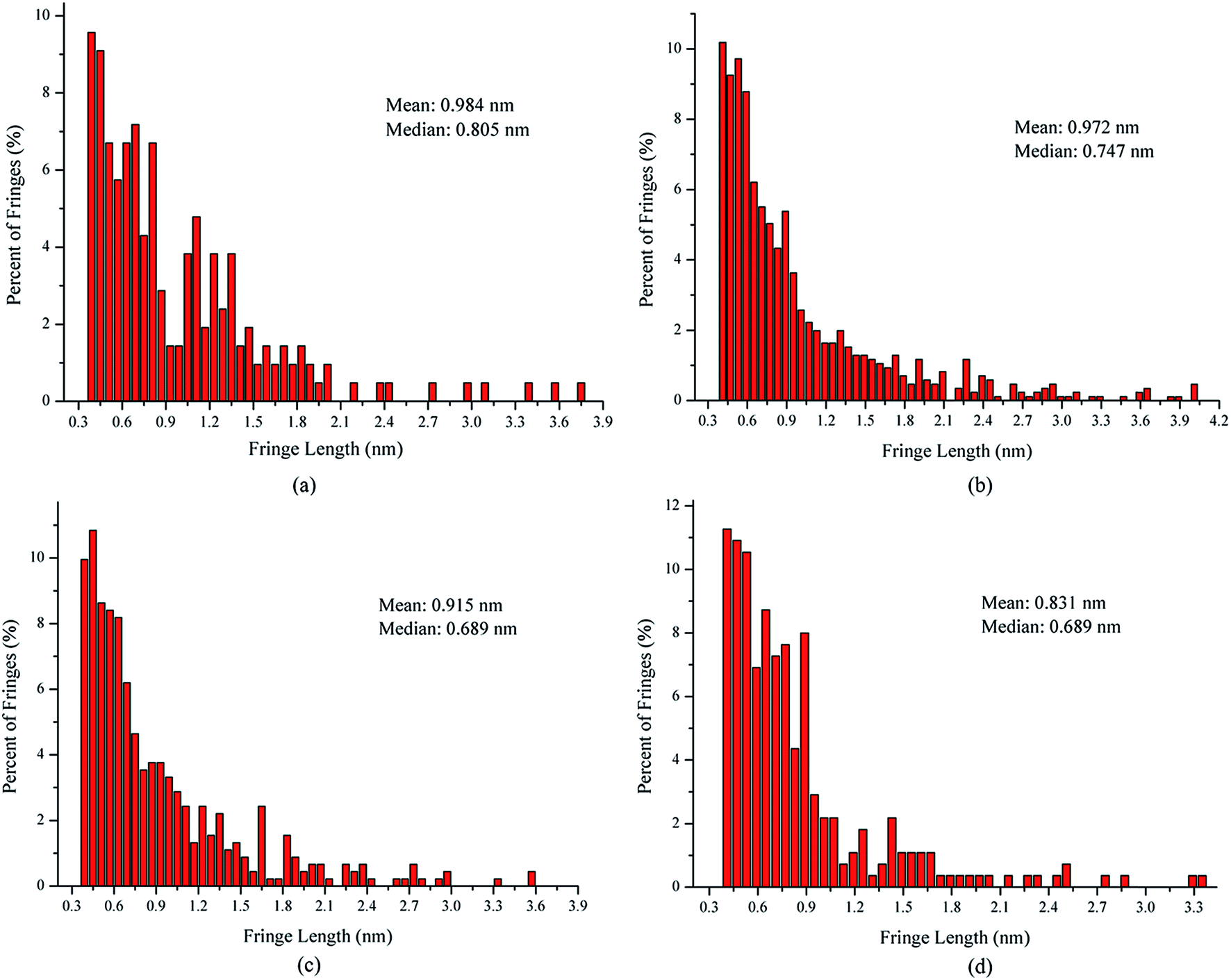 | ||
| Fig. 4 Fringe length histograms and mean values derived from the skeleton images. Soot particles were sampled at heights of 7 (a) and 14 cm (b) from the flame without ferrocene, and at heights of 7 (c) and 14 cm (d) from the flame with added ferrocene. | ||
The fringe separation is the average distance between adjacent parallel fringes, which is also known as the interlayer spacing (d002).34 Fig. 5 shows the fringe separation distance histograms and mean values obtained from the skeleton images. The fringe separation distance histogram for the soot obtained at a height of 14 cm from the flame with ferrocene has 43% of fringes greater than 0.4 nm. However, for those at the same height of the flame without ferrocene, only 26% of fringes of soot particles were greater than 0.4 nm. The soot particles obtained at a height of 7 cm from the flames with and without ferrocene have 28% and 24% of the fringes greater than 0.4 nm with respect to the fringe separation distance, respectively. The mean of the fringe separation distance histograms shows a ranking of 7 cm without ferrocene (0.375 nm) < 14 cm without ferrocene (0.376 nm) ≈ 7 cm with ferrocene (0.376 nm) < 14 cm with ferrocene (0.391 nm). Ferrocene in the flame resulted in an increase in the fringe separation distance of soot particles, in particular those obtained at a height of 14 cm from the flame.
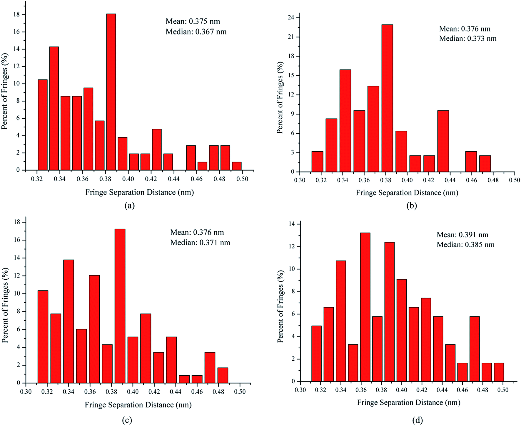 | ||
| Fig. 5 Fringe separation distance histograms and mean values derived from the skeleton images. Soot particles were sampled at heights of 7 (a) and 14 cm (b) from the flame without ferrocene, and at heights of 7 (c) and 14 cm (d) from the flame with added ferrocene. | ||
The tortuosity is a measure of the fringe curvature, obtained by calculating the ratio of the length of a fringe and the straight distance between two endpoints of the fringe.34 The tortuosity can reflect disorder within the carbon materials, and higher tortuosity usually means higher reactivity.34 Fig. 6 shows the fringe tortuosity histograms and mean values extracted from the skeleton images. As seen in Fig. 6, soot particles obtained at a height of 14 cm from the flame with ferrocene contain a high degree of curvature and have 75% of the fringes with a tortuosity greater than 1.1. However, for those obtained at the same height from the flame without ferrocene, about 68% of the fringe tortuosity histogram of soot particles is greater than 1.1. The soot particles obtained at a height of 7 cm from the flames with and without ferrocene have 70% and 65% of the fringes with a tortuosity greater than 1 nm, respectively. The mean value of the fringe tortuosity histograms shows a ranking of 7 cm without ferrocene (1.112) < 14 cm without ferrocene (1.113) < 7 cm with ferrocene (1.116) < 14 cm with ferrocene (1.144). Ferrocene in the flame resulted in an increase in the fringe tortuosity of soot particles, particularly those obtained near the flame terminus.
 | ||
| Fig. 6 Fringe tortuosity histograms and mean values derived from the skeleton images. Soot particles were sampled at heights of 7 (a) and 14 cm (b) from the flame without ferrocene, and at heights of 7 (c) and 14 cm (d) from the flame with added ferrocene. | ||
In summary, after the addition of ferrocene to the fuel, the nanostructures of soot particles obtained from the propane/oxygen flame changed. For example, the fringe length of soot particles decreased, and the fringe tortuosity and fringe separation distance of soot particles increased, especially for the soot obtained at the end of the flame. These changes in the nanostructures of soot particles are in fair agreement with the results showing that ferrocene reduced the flame temperature, both of these changes happening at the terminus of the flame. Moreover, the decreases in flame temperature result in soot particles with less graphitization, because a higher temperature facilitates graphitization. The nanostructural characteristics of soot particles obtained from flames with and without ferrocene added to propane are summarized in Table 1. The shorter and more bent fringes meant that the soot was more reactive, because more edge sites were exposed. The bent fringes usually distorted the nanostructure of soot by preventing oriented stacking of parallel fringes, thereby increasing fringe separation.12 The higher separation distances also indicated higher reactivity of soot particles. Ferrocene was found to influence the nanostructure of soot particles, which may affect their oxidation activity, and this will be discussed in Section 3.3.
| Sample | HAB (cm) | Fringe length (l/nm) | Fringe separation distance (d/nm) | Fringe tortuosity (t) | Percentage of l-values <1 nm (%) | Percentage of d-values >0.4 nm (%) | Percentage of t-values >1.1 (%) |
|---|---|---|---|---|---|---|---|
| Soot without ferrocene | 7 | 0.984 | 0.375 | 1.112 | 66 | 24 | 65 |
| 14 | 0.972 | 0.376 | 1.113 | 70 | 26 | 68 | |
| Soot with ferrocene | 7 | 0.915 | 0.376 | 1.116 | 74 | 28 | 70 |
| 14 | 0.831 | 0.391 | 1.144 | 81 | 43 | 75 |
3.2. Impact of ferrocene on functional groups of soot particles
Functional groups, especially oxygen-containing functional groups, affect the activity of soot particles. Soot particles with chemisorbed oxygen in the form of e.g. carbonyl or carboxyl groups are more active, because the energy needed to remove the oxygen is lower than if only elemental carbon is present in the soot.33 NEXAFS is able to detect these carboxyl and carbonyl groups in soot particles. The atomic or molecular environment of carbon determines its absorption peaks in a NEXAFS spectrum. The spectrum may serve as a chemical fingerprint of the soot irradiated by the X-rays.35Fig. 7 shows the carbon C(1s) NEXAFS spectra of soot particles obtained at heights of 7 and 14 cm from the flames with ferrocene added to the fuel and without ferrocene (reference soot). All spectra in Fig. 7 are typical of graphite-like materials. The peak at around 285 eV (usually known as a ‘graphitic peak’) is associated with the 1s to π* transition of sp2 bonded carbon. The broad peak at around 292 eV is attributed to the 1s to σ* transition of unsaturated and saturated carbon.36 The accumulation of peaks ranging from 286 to 289 eV is due to phenol, carboxyl, and carbonyl groups, as well as C–H bonds.34
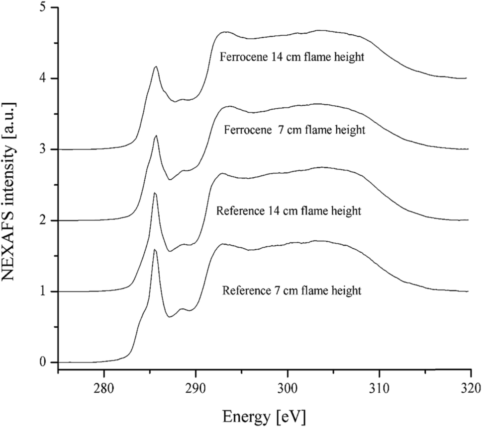 | ||
| Fig. 7 C(1s) NEXAFS spectra of soot particles obtained at heights of 7 and 14 cm from the flame with ferrocene added to the fuel and the flame without ferrocene (reference soot). | ||
The ratio of peak heights for the π-peak at 285 eV to the σ-peak at 292 eV is commonly used as a measure of the degree of graphitization in carbonaceous materials, often in connection with electron energy loss spectroscopy.8 The ferrocene soot particles have a weaker peak at 285 eV than the reference ones, as shown in Fig. 7. Peak height ratios Iπ/Iσ of soot particles are summarized in Table 2, where the ratios are 0.75 and 0.69 for ferrocene soot at flame heights of 7 and 14 cm, respectively. However, the ratios are much bigger for the reference soot particles, being 0.96 and 0.84 for those at flame heights of 7 and 14 cm, respectively. According to the peak height ratios, soot sampled at a height of 14 cm from the flame with added ferrocene seems to be the least graphitized sample among all the soot samples.
| Sample | Soot without ferrocene | Soot with ferrocene | ||
|---|---|---|---|---|
| HAB (cm) | 7 | 14 | 7 | 14 |
| Iπ/Iσ | 0.96 | 0.84 | 0.75 | 0.69 |
For peak assignments between 283 and 290 eV, a list published by G. D. Cody is helpful.37 These correspond to the 1s to π* transitions in species containing aliphatic groups, such as ketones/phenolic (286.5 eV), aliphatic side chains (287.5 eV), and carboxyls/acids at 288.3 eV.37,38 To quantify this observation, we have deconvoluted the spectra into Lorentzian peaks, as shown in Fig. 8, according to ref. 8. The first peak at 284 eV, due to the benzoquinone group, shows no obvious difference between the two samples with and without added ferrocene. However, the reference soot spectrum has a higher peak at 285 eV than the ferrocene soot spectrum. The peak at 285 eV is usually assigned to the genuine aromatic C![[double bond, length as m-dash]](https://www.rsc.org/images/entities/char_e001.gif) C bonds of carbon in a graphite arrangement. Therefore, the reference soot has a higher degree of graphitization compared to the ferrocene soot. Moreover, after the addition of ferrocene, the soot shows weak peaks at 286.5 and 288.3 eV. These peaks correspond to phenol and carboxyl groups, which are oxygen-containing functional groups. This means that ferrocene decreases the content of these oxygen-containing surface functional groups, which can accelerate soot oxidation. This could be related to the reactions between Fe decomposed from (C5H5)2Fe and O, H, and OH radicals.39 These reactions dropped the flame temperature and caused a decrease in oxygen-containing functional groups on the soot surfaces, which led to a negative effect on soot oxidation.
C bonds of carbon in a graphite arrangement. Therefore, the reference soot has a higher degree of graphitization compared to the ferrocene soot. Moreover, after the addition of ferrocene, the soot shows weak peaks at 286.5 and 288.3 eV. These peaks correspond to phenol and carboxyl groups, which are oxygen-containing functional groups. This means that ferrocene decreases the content of these oxygen-containing surface functional groups, which can accelerate soot oxidation. This could be related to the reactions between Fe decomposed from (C5H5)2Fe and O, H, and OH radicals.39 These reactions dropped the flame temperature and caused a decrease in oxygen-containing functional groups on the soot surfaces, which led to a negative effect on soot oxidation.
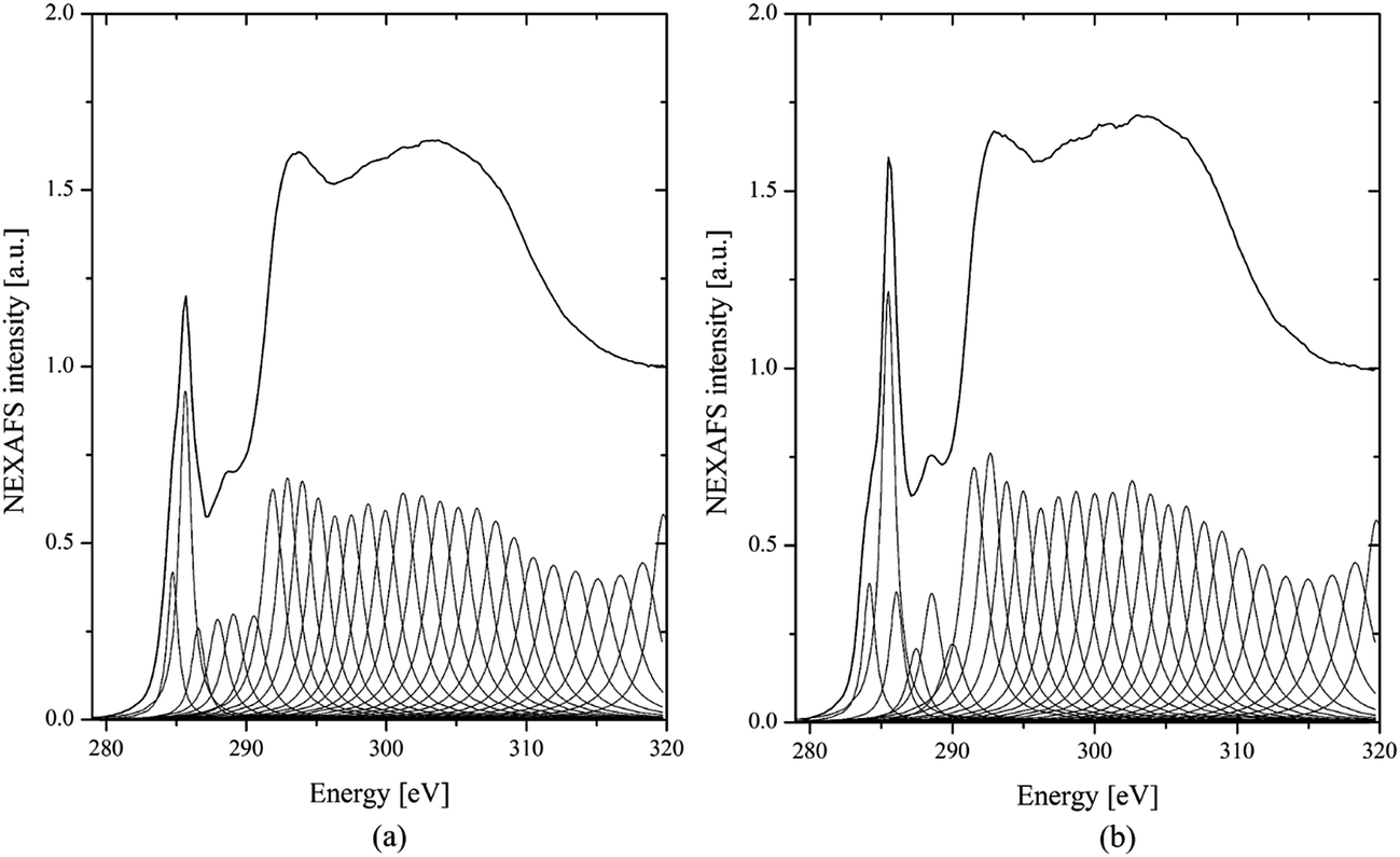 | ||
| Fig. 8 C(1s) NEXAFS spectra of soot particles obtained at a height of 7 cm from the flame with ferrocene added to the fuel (a) and reference soot (b) after deconvolution. | ||
It is of interest to note that ferrocene can make a significant difference to the surface functional groups of soot particles obtained from the propane/oxygen flame. It decreases the peak height ratio of the π-peak at 285 eV and the σ-peak at 292 eV, and suppresses the graphitization of soot particles, especially near the flame terminus. This is consistent with the findings that ferrocene drops the flame temperature and changes soot nanostructure at the top of the flame. However, the reduction of oxygen-containing functional groups is not beneficial for the oxidation of soot, after adding ferrocene to the fuel.
3.3. Impact of ferrocene on oxidation of soot particles
Fig. 9 shows the dynamic TGA profiles of soot particles obtained at heights of 7 and 14 cm from the flames with and without ferrocene added to the fuel. The weight loss below 300 °C is mainly caused by desorption of water adsorbed on soot and easily decomposable oxygen complexes on the surface.40 However, after the addition of ferrocene, the thermal stability of soot decreases sharply when the temperature is higher than 300 °C, especially for the soot obtained at a flame height of 14 cm. This could be related to the degree of graphitization of the soot particles. Ferrocene affects the graphitization of soot by changing its nanostructure and molecular structure. As for the soot particles obtained at a height of 7 cm from flames with and without ferrocene added to the fuel, these show very similar TGA curves. This is relevant to the effects of ferrocene on flame temperature and soot nanostructure, which are particularly prominent near the flame terminus, and less obvious at a flame height of 7 cm. | ||
| Fig. 9 Dynamic TGA results for the soot particles sampled at different flame heights with and without ferrocene added to the fuel. | ||
The degree of graphitization is related to the length and orientation of graphene layers, which compose the primary soot particles. With the increasing graphitization, the fringe lengths become larger, while the fringe tortuosities and separation distances decrease. Moreover, the ratio of the π-peak at 285 eV to the σ-peak at 292 eV is also used to investigate the degree of graphitization. With a higher degree of graphitization, the spectrum of soot shows a stronger “graphite” peak at 285 eV, which is assigned to aromatic CC bonds. The graphitization of soot influences its properties, making it more difficult to oxidize.
For the soot particles obtained from propane/oxygen flames with added ferrocene, the fringe separation distances and tortuosity increased, while the fringe length was reduced, and the ratio of the π-peak to the σ-peak also decreased. The addition of ferrocene results in soot with a lower degree of graphitization and better oxidation activity at low temperature, especially for the soot obtained at a flame height of 14 cm. The reduction of the temperature near the flame terminus by ferrocene affects the soot nanostructure, and these changes promote soot oxidation.
Ferrocene also influences soot oxidation activity by changing the functional groups on its surface. The iron decomposed from ferrocene reacts with oxygen, and these reactions drop the flame temperature and reduce the oxygen-containing functional groups on the soot. Therefore, the reduction of these functional groups leads to soot particles requiring more energy to be oxidized.
4. Conclusions
According to the analyses of skeleton images of soot particles by the image processing procedure, three parameters are used to quantify the nanostructures of soot obtained from a propane/oxygen flame with or without ferrocene added to the fuel. After addition of ferrocene to the fuel, the fringe lengths of soot become shorter, while the fringe tortuosities and fringe separation distances increase. These parameters indicate that ferrocene suppresses graphitization of soot, especially near the flame terminus. These changes in soot may be relevant to the decreases in flame temperature at the end of the flame. The NEXAFS data show that the peaks of oxygen-containing functional groups of soot decrease when ferrocene is added, and this is related to the reactions between oxygen and iron decomposed from ferrocene. Soot is partially oxidized by the iron oxide formed in these reactions, and bigger inner cores appear. The decrease in the peak height ratio of the π-peak to the σ-peak also suggests that ferrocene lowers the degree of graphitization of soot. The HRTEM, NEXAFS, and TGA analyses of soot particles indicate that ferrocene affects the soot oxidation activity by suppressing its graphitization and changing the functional groups on its surface.Acknowledgements
This work is supported by National Natural Science Foundation of China (No. 51376171), the Science and Technology Fund of Anhui Province for Outstanding Youth (1508085J01), and the International Technology Cooperation Plan of Anhui (No. 1503062030).References
- J. O. Anderson, J. G. Thundiyil and A. Stolbach, J. Med. Toxicol., 2012, 8, 166–175 CrossRef CAS PubMed.
- P. Stelmachowski, A. Kopacz, P. Legutko, P. Indyka, M. Wojtasik, L. Ziemiański, G. Żak, Z. Sojka and A. Kotarba, Catal. Today, 2015, 257, 111–116 CrossRef CAS.
- G. R. Kannan, R. Karvembu and R. Anand, Appl. Energy, 2011, 88, 3694–3703 CrossRef CAS.
- K. Tian, Z. S. Li, S. Staude, B. Li, Z. W. Sun, A. Lantz, M. Alden and B. Atakan, Proc. Combust. Inst., 2009, 32, 445–452 CrossRef CAS.
- Z. Zhang and R. Balasubramanian, Appl. Energy, 2015, 146, 270–278 CrossRef CAS.
- M. P. Herring, P. M. Potter, H. Y. Wu, S. Lomnicki and B. Dellinger, Proc. Combust. Inst., 2013, 34, 1749–1757 CrossRef PubMed.
- J. Mitchell, J. L. LeGarrec, G. Saidani, F. Lefeuvre and S. Stasio, Energy Fuels, 2013, 27, 4891–4898 CrossRef CAS.
- A. Braun, F. E. Huggins, K. E. Kelly, B. S. Mun, S. N. Ehrlich and G. P. Huffman, Carbon, 2006, 44, 2904–2911 CrossRef CAS.
- A. Trubetskaya, P. A. Jensen, A. D. Jensen, A. D. Garcia Llamas, K. Umeki, D. Gardini, J. Kling, R. B. Bates and P. Glarborg, Appl. Energy, 2016, 171, 468–482 CrossRef CAS.
- K. Yehliu, R. L. Vander Wal and A. L. Boehman, Carbon, 2011, 49, 4256–4268 CrossRef CAS.
- B. Apicella, P. Pré, M. Alfè, A. Ciajolo, V. Gargiulo, C. Russo, A. Tregrossi, D. Deldique and J. N. Rouzaud, Proc. Combust. Inst., 2015, 35, 1895–1902 CrossRef CAS.
- R. L. Vander Wal, A. J. Tomasek, M. I. Pamphlet, C. D. Taylor and W. K. Thompson, J. Nanopart. Res., 2004, 6, 555–568 CrossRef CAS.
- C. Esangbedo, A. L. Boehman and J. M. Perez, Tribol. Int., 2012, 47, 194–203 CrossRef CAS.
- P. Toth, A. B. Palotas, T. A. Ring, E. G. Eddings, R. L. Vander Wal and J. S. Lighty, Combust. Flame, 2015, 162, 2422–2430 CrossRef CAS.
- S. Stasio and A. Braun, Energy Fuels, 2006, 20, 187–194 CrossRef.
- K. Heymann, J. Lehmann, D. Solomon, M. W. I. Schmidt and T. Regier, Org. Geochem., 2011, 42, 1055–1064 CrossRef CAS.
- A. Braun, B. S. Mun, F. E. Huggins and G. P. Huffman, Environ. Sci. Technol., 2007, 41, 173–178 CrossRef CAS PubMed.
- S. Banerjee, T. Hemraj-Benny, M. Balasubramanian, D. A. Fischer, J. A. Misewich and S. S. Wong, Chem. Commun., 2004, 7, 772 RSC.
- J. O. Muller, D. S. Su, U. Wild and R. Schlogl, Phys. Chem. Chem. Phys., 2007, 9, 4018 RSC.
- P. J. Fallon, V. S. Veerasamy, C. A. Davis, J. Robertson, G. A. Amaratunga, W. I. Milne and J. Koskinen, Phys. Rev. B: Condens. Matter Mater. Phys., 1993, 48, 4777–4782 CrossRef CAS.
- C. Hu, W. Li, Q. Lin, X. Cheng, Q. Huang, H. Zhang and Z. Wang, J. Energy Inst., 2016, 1–9 Search PubMed.
- R. L. Vander Wal and A. J. Tomasek, Combust. Flame, 2003, 134, 1–9 CrossRef CAS.
- R. L. Vander Wal and A. J. Tomasek, Combust. Flame, 2004, 136, 129–140 CrossRef CAS.
- J. P. Cain, P. L. Gassman, H. Wang and A. Laskin, Phys. Chem. Chem. Phys., 2010, 12, 5206–5218 RSC.
- Y. H. Kim, Y. T. Kim, S. H. Kim and D. Lee, Carbon, 2010, 48, 2072–2084 CrossRef CAS.
- G. Schulz, S. Tamborim, G. Cardoso, T. Santos, E. Lissner and R. Cataluna, Green Chem., 2012, 14, 514–518 RSC.
- K. Yehliu, R. L. Vander Wal and A. L. Boehman, Combust. Flame, 2011, 158, 1837–1851 CrossRef CAS.
- A. Liati, A. Spiteri, P. D. Eggenschwiler and N. Vogel-Schäuble, J. Nanopart. Res., 2012, 14, 1–18 CrossRef.
- D. S. Su, J. O. Müller, R. E. Jentoft, D. Rothe, E. Jacob and R. Schlögl, Top. Catal., 2004, 30, 241–245 CrossRef.
- Z. Ma, L. Li, Y. Chao, N. Kang, B. Xu and J. Wu, Energy Fuels, 2014, 28, 4376–4382 CrossRef CAS.
- R. L. Vander Wal, A. Yezerets, N. W. Currier and D. H. Kim, Carbon, 2007, 45, 70–77 CrossRef CAS.
- K. Yehliu, R. L. Vander Wal, O. Armas and A. L. Boehman, Combust. Flame, 2012, 159, 3597–3606 CrossRef CAS.
- A. Liati, P. Dimopoulos Eggenschwiler, D. Schreiber, V. Zelenay and M. Ammann, Combust. Flame, 2013, 160, 671–681 CrossRef CAS.
- J. Pan, S. Wang, Y. Ju, Q. Hou, Q. Niu, K. Wang, M. Li and X. Shi, J. Nat. Gas Sci. Eng., 2015, 27, 1852–1862 CrossRef CAS.
- A. Braun, F. E. Huggins, N. Shah, Y. Chen, S. Wirick, S. B. Mun, C. Jacobsen and G. P. Huffman, Carbon, 2005, 43, 117–124 CrossRef CAS.
- H. J. Seong and A. L. Boehman, Combust. Flame, 2012, 159, 1864–1875 CrossRef CAS.
- G. D. Cody, H. Ade, S. Wirick, G. D. Mitchell and A. Davis, Org. Geochem., 1998, 28, 441–455 CrossRef CAS.
- P. Parent, C. Laffon, I. Marhaba, D. Ferry, T. Z. Regier, I. K. Ortega, B. Chazallon, Y. Carpentier and C. Focsa, Carbon, 2016, 101, 86–100 CrossRef CAS.
- V. M. Shvartsberg, T. A. Bolshova and O. P. Korobeinichev, Energy Fuels, 2010, 24, 1552–1558 CrossRef CAS.
- K. Krishna, A. Bueno-López, M. Makkee and J. A. Moulijn, Appl. Catal., B, 2007, 75, 210–220 CrossRef CAS.
| This journal is © The Royal Society of Chemistry 2017 |