
 Open Access Article
 This Open Access Article is licensed under a Creative Commons Attribution-Non Commercial 3.0 Unported Licence
Layered hybrid phase Li2NaV2(PO4)3/carbon dot nanocomposite cathodes for Li+/Na+ mixed-ion batteries
Jichao Wang a,
Xudong zhang*a,
Wen He*ab,
Yuanzheng Yueab,
Yaoyao Wanga and
Chuanjiang Zhanga
a,
Xudong zhang*a,
Wen He*ab,
Yuanzheng Yueab,
Yaoyao Wanga and
Chuanjiang Zhanga
aShandong Key Laboratory of Glass and Functional Ceramics, Qilu University of Technology, Jinan 250353, China. E-mail: zxd1080@126.com; hewen1960@126.com; Fax: +86 531 89631518; Tel: +86 531 89631716
bSection of Chemistry, Aalborg University, DK-9000 Aalborg, Denmark
First published on 12th January 2017
Abstract
Hybrid phase Li2NaV2(PO4)3 (H-LNVP) is one of the most promising cathode materials for Li+/Na+ mixed-ion batteries. Here we have successfully synthesized layered hybrid phase Li2NaV2(PO4)3/carbon dot (H-LNVP/CD) nanocomposites via a simple sol–gel and carbon thermal reduction method and its inserted-extracted mechanism is investigated. As a novel composite cathode, H-LNVP/CD nanocomposite cathode delivers 158 mA h g−1 of reversible capacity at 0.1C in a Li+/Na+ mixed-ion cell with the electrochemically active redox reactions of V3+/V4+ and V4+/V5+, which is far higher than single phase contrastive samples. The cell exhibits one main high voltage plateau with well-defined discharge voltage near 3.7 V, and a coulombic efficiency of approximate 100 percent at 10C. Because the carbon dots on the surface of layered H-LNVP nanoparticles can remarkably enhance their electronic conductivity, the cell still exhibits a higher specific capacity of about 89.4 mA h g−1 at 10C. These results are attributed to the nanocomposite structure of H-LNVP and CDs. This work will contribute to the development of Li+/Na+ mixed-ion batteries.
1. Introduction
Lithium ion batteries (LIBs) have proved themselves to be an advanced electrochemical energy storage and conversion system for electric vehicles (EVs) and stationary energy storage for solar power owing to their high operating voltage and relatively high energy density.1–5 Recently vanadium-based phosphates have been gaining enormous attention due to their low cost, excellent thermal stability and cycle performance.6–11 Among these phosphates, monoclinic structured Li3V2(PO4)3 (M-LVP) has attracted much attention for its high theoretical capacity, high operating potential, long cycle life and reliable safety.12–14 However, its practical application is strongly limited due to its multi potential plateaus.Rhombohedral structure is the other existent phase of Li3V2(PO4)3.15–18 Compared with multi-plateaus of M-LVP, rhombohedral Li3V2(PO4)3 (R-LVP) only has one potential plateau at about 3.7 V in the range of 3.0–4.3 V due to the two lithium reversible removed. However, it is difficult to directly synthesize R-LVP since its structural stability is poorer than M-LVP. Goodenough et al.19,20 firstly prepared R-LVP, proving that it can be formed directly when Li+ ions are partially substituted by Na+ ions. To compare with lithium, sodium resources are unlimited everywhere and lower in price. Besides, only two of the three Li+ ions extract/insert in R-LVP. Therefore, it is meaningful to substitute inactive lithium ions with abundant sodium cations. Two lithium ions of rhombohedral phase Li2NaV2(PO4)3 (R-LNVP) can be reversibly removed with a redox potential of ∼3.7 V and deliver a theoretical capacity of 133 mA h g−1. The as-prepared Na-doped product has rhombohedral structure and shows excellent electrochemical properties whether it consists of a single phase or hybrid phases. Single-phase Li2NaV2(PO4)3 is always prepared by a complex ion exchange process from rhombohedral Na3V2(PO4)3 (R-NVP).21–23 On the other hand, it has been confirmed that a hybrid phase Li2NaV2(PO4)3 (H-LNVP) composite can be used as a cathode material with its excellent electrochemical properties.24–27 On this basis, sol–gel route has been proposed to synthesize the hybrid phase composite in recent years. Rechargeable sodium batteries (NIBs) have been proposed as an alternative system for LIBs with safety and cyclability issues. However, research efforts for pure sodium battery systems have encountered numerous problems, such as low reversible capacity, low available energy density and insufficient cycle life (less than 100 cycles) with rapid capacity decay. The emergence of Li+/Na+ mixed-ion batteries balance the advantageous features of NIBs and LIBs. Hence, the study of Li+/Na+ mixed-ion batteries operating at room-temperature has become an important research direction and aroused wide attention.28
Nature is the greatest factory producing various biomaterials with complicated and even multiple nanoscale assemblies to satisfy specific requirements.29,30 The new strategies for synthesis of functional nanomaterials can be derived from multifunctional biological materials. Wei et al.31 synthesized a biocarbon coated Li3V2(PO4)3/C (LVP-C) cathode material using recycled tea as both the structural template and biocarbon source. The LVP-C nanocomposite delivered a high initial discharge capacity of 132 mA h g−1 in the potential range of 3.0–4.3 V. The good electrochemical performance indicated that biocarbon improved the electron and lithium ion diffusivity. Adenosine triphosphate (ATP) is a kind of instability of energetic compounds and composed by 1 molecules of adenine, 1 molecules of DNA and 3 molecules of phosphoric acid. Zhang et al.32 synthesized the mesoporous biocarbon nanowire coated LiFePO4 with high-energy quantum dots (MBCNW-LFP-HEQDs) by using a multifunctional high-energy biomolecule—adenosine triphosphate as a phosphorus source, a nucleating agent, a structural template and a biocarbon source. This was the first time to use the high-energy biomolecule ATP as biological template in high-power lithium-ion batteries and the electrochemical performance of the nanostructured LiFePO4 was enhanced. Compared to the usual LiFePO4 nanoparticle (10–100 nm) cathode, the as-preparation cathode shows the best first discharge capacity of 197 mA h g−1 at the 0.1C rate, which is about 1.1 times the theoretical specific capacity of LiFePO4 (170 mA h g−1).
Tang et al.24 initially prepared hybrid Li2NaV2(PO4)3 with high ratio rhombohedral phase (90%) through a simple solid state reaction, and the prepared composite delivers a discharge capacity of 119.1 mA h g−1, but the rate performance is poor. Based on that H-LNVP (rhombohedral LVP, rhombohedral NVP and monoclinic LVP coexistent with a ratio of 60.9![[thin space (1/6-em)]](https://www.rsc.org/images/entities/char_2009.gif) :31.6:7.5) was synthesized via sol–gel method by Mao et al.25 The synthesised H-LNVP exhibits a discharge specific capacity of 123.3 mA h g−1 at 0.5C as a cathode, which delivers better electrochemical performance because its structure is more stable than that of R-LNVP. The sodium source in the synthetic sample is typically derived from inorganic salts such as NaF and Na2CO3. But the method of using the biological macromolecule as a sodium source to synthesize H-LNVP with excellent electrochemical performance has not been attempted.
:31.6:7.5) was synthesized via sol–gel method by Mao et al.25 The synthesised H-LNVP exhibits a discharge specific capacity of 123.3 mA h g−1 at 0.5C as a cathode, which delivers better electrochemical performance because its structure is more stable than that of R-LNVP. The sodium source in the synthetic sample is typically derived from inorganic salts such as NaF and Na2CO3. But the method of using the biological macromolecule as a sodium source to synthesize H-LNVP with excellent electrochemical performance has not been attempted.
In recent years, H-LNVP was synthesized via a sol–gel method and carbon thermal reduction method to replace the complex ion exchange process. Herein, the high-energy biomolecule—ATP was used as a sodium source, anionic surfactants and a biocarbon source in the synthetic process. The high-energy biomolecules formed carbon dots (CDs) with a feature size of less than 10 nm in the surface of layered structure by thermal decomposition reducing method. On account of the high surface-to-mass ratio of CDs, much more lithium ions can be situated on the sites.33–35 Based on the excellent physical properties of CDs such as quantum tunneling effect and high electron mobility, Li+ ions and electrons transport efficiency was increased.36,37 Moreover, the sheetlike carbon composites can significantly accelerate the charge transfer rate. As a consequence, the as-prepared H-LNVP delivers a reversible capacity of 158 mA h g−1 at 0.1C, surpassing the theoretical capacity (133 mA h g−1) of R-LVP. It also exhibits better coulombic efficiency and a higher specific capacity of about 89.4 mA h g−1 at 10C. The plateaus remained at 3.6 and 4.1 V vs. Li/Li+ in the charge–discharge curves of M-LVP, which play the role of state-of-charge and depth-of-discharge. In general, the fabrication strategy of H-LNVP materials is beneficial to generating high performance electrode materials for LIBs, which have highly reversible specific capacity, good rate ability and remarkable cyclability.
2. Experimental
2.1 Synthesis of H-LNVP nanocomposites
The reagents used in this work were NH4VO3 (99%, Tianjin Bodi Chemical Co. Ltd.), C2H2O4·2H2O (99.5%, Tianjin Bodi Chemical Co. Ltd.), NH4H2PO4 (99%, Tianjin Bodi Chemical Co. Ltd.), Li2CO3 (97%, Tianjin Guangfu Fine Chemical Research Institute), and acyl nucleoside triphosphate disodium salt (Na2ATP, Xuzhou Ryen Pharma. Co. Ltd.), distilled water was used during synthesis of the H-LNVP nanocomposites. H-LNVP cathode material were prepared using the biotemplate, sol–gel and carbon thermal reduction method. The general synthesis procedure is shown in Fig. 1. 1 g Na2ATP was added into a beaker and incubated for 30 min at 100 °C in a water bath pot. Then the Na2ATP was cooled at room temperature to release the surface charge of anionic phosphate groups in the ATP biomolecule. Oxalic acid and NH4VO3 in stoichiometric ratios were dissolved in 100 mL deionized water with magnetic stirring at 70 °C until a clear blue solution of VOC2O4 was formed. Then Na2ATP biotemplate solution after cooling, stoichiometric NH4H2PO4 and Li2CO3 were added to the blue solution with magnetic stirring at 70 °C until the formation of gel, and then the gel dried in an oven at 100 °C. The obtained dark green product was sintered at 750 °C in a N2 atmosphere for 8 h, and the final obtained product was a black powder. LVP samples without ATP biotemplate were prepared by the same process for comparison. LNVP was prepared via ion exchange from Na3V2(PO4)3. The rhombohedral Na3V2(PO4)3 was synthesized via the same method with LVP while replaced the Li2CO3 with Na2CO3. The three samples were named H-LNVP (with ATP biotemplate), LNVP and LVP (without ATP biotemplate), respectively.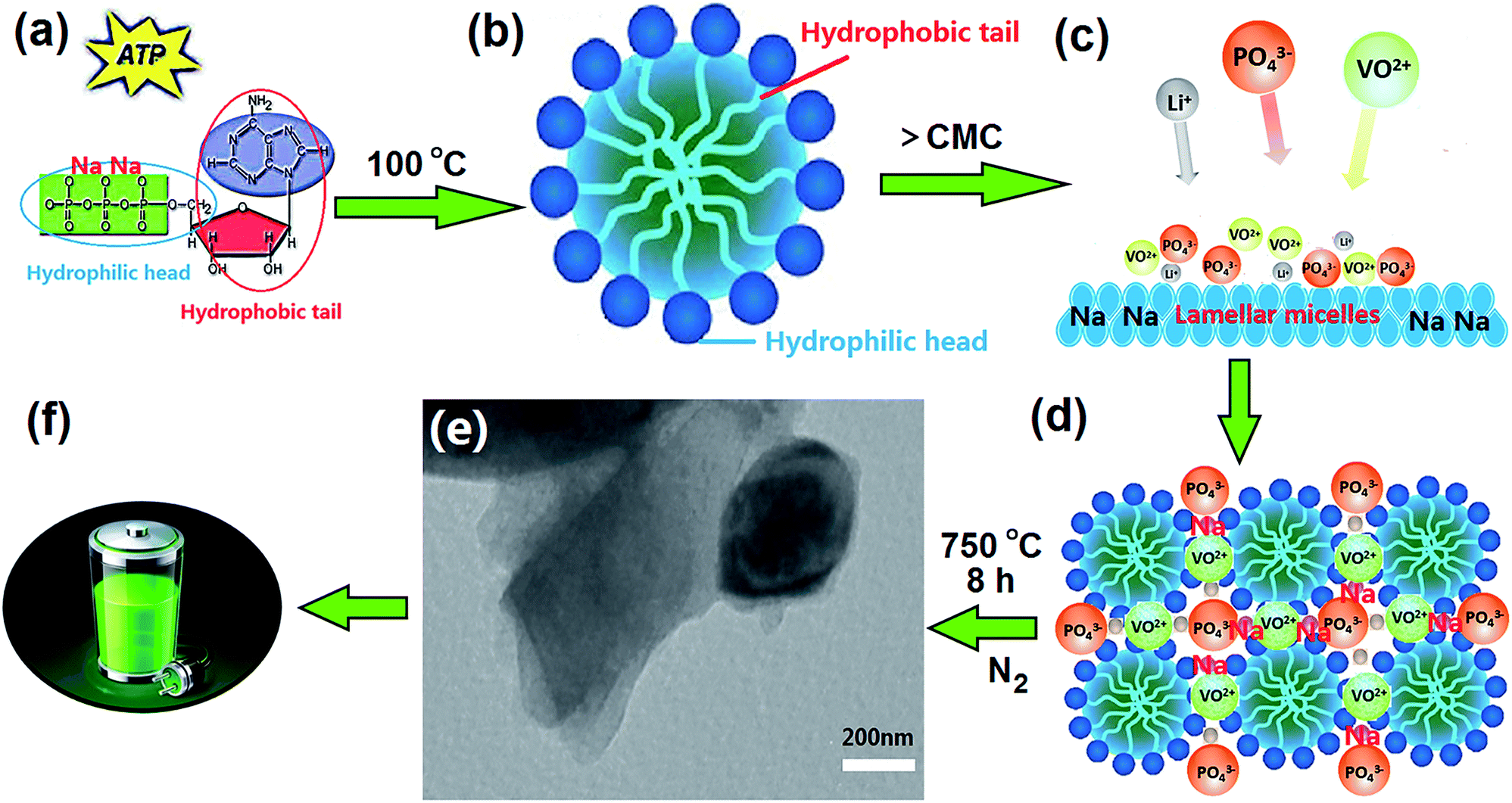 | ||
| Fig. 1 Schematic drawing of the synthesis of H-LNVP nanocomposites. | ||
2.2 Characterization
The phase composition of the synthesized samples was analyzed by X-ray diffraction (XRD) employing a Cu-Kα X-ray diffractometer (PANalytical X'Pert PRO; Netherlands). The diffraction patterns were collected over a diffraction angle 2θ range of 10–70°, with an acquisition time of 12 s at 0.02° step size. Raman spectroscopic analysis was performed with a Renishaw In-Via Raman microscopic instrument equipped with an Ar+ laser (λ = 785 nm) at 50× aperture. Fourier transform infrared spectroscopy (FT-IR) measurements were performed using a Nicolet Nexus spectrometer (Nicolet, NEXUS 470, USA) and by using a KBr wafer technique. X-ray photoelectron spectroscopy (XPS) measurements were performed using a Kratos Axis Ultra DLD (delay line detector) spectrometer equipped with amonochromatic Al Kα X-ray source (1486.6 eV). The morphology and crystal structures of the synthesized samples were characterized by high-resolution transmission electron microscopy (HRTEM). HRTEM images were obtained using a Philips Tecnai 20U-TWIN microscope, working at 300 kV. A trace amount of sample was dispersed in ethanol solution by sonication, and then deposited on a carbon-coated copper grid. HRTEM images were obtained at the Scherzer defocus (Δf = −41.25 nm) to optimize the transfer function of the optical system balancing the effect of spherical aberration.Scanning electron microscopy (SEM) images of the samples were obtained by a Quanta 200 scanning electron microscope with an accelerating voltage of 20 kV.
2.3 Electrochemical evaluation
The charge–discharge performances were determined with CR 2032 coin cells. The cathode materials were prepared by mixing the synthesized sample with acetylene black and poly (vinylidene fluoride) in a weight ratio of 80:10:10 in N-methyl pyrrolidone to ensure homogeneity. Then the mixture was pressed to a piece on an Al-foil with about 0.02 mm in thickness, dried under the air atmosphere at 60 °C for 5 h and vacuum atmosphere at 120 °C for 10 h and cut into circular strips of 15 mm in diameter. The mass calculation of active materials was carried out based on the 80% of difference between the mass of synthesized materials coated Al foil and the mass of pristine Al foil. The cells were assembled in a glove box filled with high-purity argon, where lithium metal was used as an anode, polypropylene film as separator, and 1 M LiPF6 as an electrolyte consisting of ethylene carbonate/dimethyl carbonate/ethylene methyl carbonate in a volume ratio of 1:1:1 as electrolyte. The charge–discharge performances of the synthesized samples were tested on Channels battery analyzer (CT3008W) at different current densities between 2.0 and 4.3 V cut-off voltage using the coin-cells. The electrochemical impedance (EIS) and cyclic voltammetry (CV) measurements were performed on a PARSTAT 2263 electrochemical workstation. EIS was also recorded with the frequency ranging from 100 kHz to 10 mHz and AC signal of 5 mV in amplitude as the perturbation. The voltage range of the CV measurements was 3.0–4.3 V and the scanning rate was 0.1 mV s−1. All the tests were performed at room temperature.
3. Results and discussion
3.1 Forming mechanism of H-LNVP/CQD nanocomposites
Fig. 1 shows schematic drawing of the synthesis of H-LNVP nanocomposites. The chemical structure of ATP has been described in detail in our previous studies (Fig. 1a).32 The critical micelle concentration (CMC) of ATP was measured by using the conductivity meter method and equal to 1.5 g L−1, which was tested in water (no other additives or salts) at 25 °C, atmospheric pressure. The concentration of ATP in this experiment is far greater than the CMC, thus causing the ATP molecules self-assemble and form lamellar micelles with negative charges (Fig. 1b and c). When PO43−, VO2+ and Li+ were added to the lamellar micelles solution, the sol–gel reaction process occured on the surface of lamellar micelles due to electrostatic interaction (Fig. 1c). Herein, the lamellar micelles formed by ATP molecules are used as host matrixes of heterogeneous phase nucleation and crystal growth for the H-LNVP nanoparticles (Fig. 1d). During pyrolytic degradation, the carbon compound backbone of ATP was decomposed to form a sheetlike biocarbon matrixes by carbonization of the agglomerate micelle, and H-LNVP nanoparticles and carbon quantum dots are homogeneously embedded in the biocarbon matrixes (Fig. 1e). The sheetlike biocarbon matrixes can significantly increase conductivity of H-LNVP and thus facilitate diffusion of lithium-ion (Fig. 1f).3.2 Characterization analysis of synthesized samples
The XRD patterns of as-prepared samples are shown in Fig. 2. The diffraction peaks of H-LNVP in Fig. 2a can be indexed as three-phase structure of R-LVP with space group of R![[3 with combining macron]](https://www.rsc.org/images/entities/char_0033_0304.gif) , R-LNVP with space group of Rc and M-LVP with space group of P21/n. For the XRD patterns of LNVP, the diffraction peaks can be indexed as two-phase structure of R-LVP and R-NVP. According to the TGA analysis, the carbon contents of H-LNVP, LNVP and LVP are 4.2%, 1.0%, 1.3%, respectively. It should be noted that no diffraction peaks of carbon crystal are observed in Fig. 2, indicating that the carbon in these samples may be amorphous or the content of graphite-like carbon is too low to be detected. In order to further confirm the accurate composition the Rietveld refinement of X-ray powder diffraction pattern for H-LNVP sample at room temperature was performed. Rietveld refined XRD pattern is shown in Fig. 2b. The structural refinement results show that H-LNVP sample is comprised of rhombohedral Li3V2(PO4)3 (R-LVP), monoclinic Li3V2(PO4)3 (M-LVP) and rhombohedral Na3V2(PO4)3 (R-NVP), wherein the weight percentage of R-LVP, M-LVP and R-NVP is 59.5, 12.4 and 28.1%, respectively. In addition, their lattice parameters are in good agreement with those of the references, as shown in Table 1. The slight variance of lattice information between the present work and the references should be resulted from the difference of Na+ source. The equation used to calculate the lattice parameters is Bragg equation:
, R-LNVP with space group of Rc and M-LVP with space group of P21/n. For the XRD patterns of LNVP, the diffraction peaks can be indexed as two-phase structure of R-LVP and R-NVP. According to the TGA analysis, the carbon contents of H-LNVP, LNVP and LVP are 4.2%, 1.0%, 1.3%, respectively. It should be noted that no diffraction peaks of carbon crystal are observed in Fig. 2, indicating that the carbon in these samples may be amorphous or the content of graphite-like carbon is too low to be detected. In order to further confirm the accurate composition the Rietveld refinement of X-ray powder diffraction pattern for H-LNVP sample at room temperature was performed. Rietveld refined XRD pattern is shown in Fig. 2b. The structural refinement results show that H-LNVP sample is comprised of rhombohedral Li3V2(PO4)3 (R-LVP), monoclinic Li3V2(PO4)3 (M-LVP) and rhombohedral Na3V2(PO4)3 (R-NVP), wherein the weight percentage of R-LVP, M-LVP and R-NVP is 59.5, 12.4 and 28.1%, respectively. In addition, their lattice parameters are in good agreement with those of the references, as shown in Table 1. The slight variance of lattice information between the present work and the references should be resulted from the difference of Na+ source. The equation used to calculate the lattice parameters is Bragg equation:|
2dsinθ = nλ
| (1) |
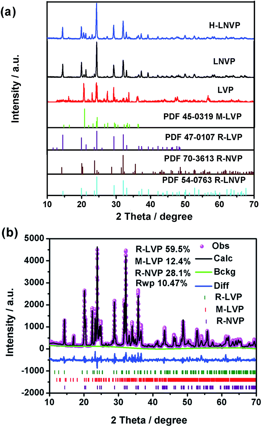 | ||
| Fig. 2 (a) XRD patterns and the standard PDF cards of the different samples. (b) Rietveld refinement pattern of the X-ray diffraction data for H-LNVP sample (the red dots, black line, green line and blue line represent the observed, calculated, back ground and difference patterns, respectively). | ||
| Samples | a (Å) | b (Å) | c (Å) | V (Å3) | Ref. |
|---|---|---|---|---|---|
| M-LVP | 8.562 | 12.005 | 8.612 | 889.867 | 31 |
| R-LVP | 8.316 | 8.316 | 22.459 | 1342.77 | 17 |
| R-LNVP | 8.325 | 8.325 | 22.491 | 1349.92 | 17 |
| M-LVP in H-LNVP | 8.562 | 12.055 | 8.629 | 890.76 | Present work |
| R-LVP in H-LNVP | 8.342 | 8.342 | 22.468 | 1344.2 | Present work |
| R-LNVP in H-LNVP | 8.342 | 8.343 | 22.516 | 1351.24 | Present work |
| LNVP | 8.302 | 8.302 | 22.743 | 1352.33 | Present work |
| LVP | 8.560 | 12.007 | 8.592 | 883.18 | Present work |
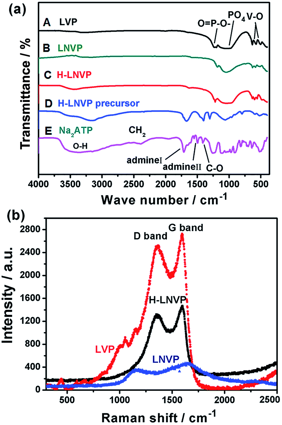
The bonding structure of the different samples is studied by FT-IR in Fig. 3a. Fig. 3a(E) shows the infrared spectrum of pure ATP, in which the band at 3500 cm−1 is attributed to the O–H stretching vibration in the water structure, the bands near 1692 cm−1 and 1438 cm−1 represent the amino I and amino II compound, respectively. The 1124 cm−1 band is caused by the C–O bond in the nucleus, and the bands from 500 cm−1 to 800 cm−1 are caused by the three phosphate in the ATP molecule. By comparing Fig. 3a(C) with Fig. 3a(D), two main changes are seen from FTIR spectra. First, all the peaks of amino acid in the H-LNVP precursor move to lower wave numbers, indicating that there are chemical bonds between vanadium ions and biomolecules. Accordingly it can be inferred that ATP biomolecules combine with vanadium ions via amino acids. Second, the band at 1045 cm−1 is enhanced mainly due to the superposition of C–O and PO43−. These results indicate that the hydroxyl groups (OH−) in the ribose and the OPO32− in triple phosphate play a very important role in the chemical binding of ATP macromolecules and vanadium ions. Comparing with Fig. 3a(A), in Fig. 3a(B and C), it can be seen that the V–O and P–O peaks shift to higher wave numbers and their peak intensity was obviously reduced because Li+ ions are partially substituted by Na+ ions in the structure. Besides, comparing with Fig. 3a(C), in Fig. 3a(B) the PO43−, P–O and V–O peaks were enhanced, which indicate the presence of a situ composite link between H-LNVP nanoparticles and the biologically active carbon network.
 | ||
| Fig. 3 (a) FTIR spectra of the different samples, (A) is LVP sample, (B) is LNVP sample, (C) is H-LNVP, (D) is H-LNVP precursor and (E) is Na2ATP. (b) Raman spectra of the H-LNVP, LNVP and LVP samples. | ||
Raman spectroscopy is a powerful tool to study the properties and structural features of coated carbon in the surface region of sample particles. Fig. 3b shows that the different samples all display two peaks (D-band and G-band) at 1000–1800 cm−1, indicating the existence of both amorphous and graphite-like carbon. The G (graphite) peak is associated with the ordered sp2 carbon, whereas the D (disorder-induced phonon mode) peak is due to the disordered portions of carbon. The ID/IG ratio is 0.61 for H-LNVP, 0.7 for LNVP and 0.89 for LVP, which indicates that the degree of graphitizing for carbon layer coated on the surface of H-LNVP nanoparticle is higher. Graphite-like carbon would result in an improved electrical conductivity. It can be also seen that the band intensity of D and G for H-LNVP is stronger than that of LNVP, which means that H-LNVP has better surface carbon structure. As shown in Fig. 4a, the binding energy (B.E.) of V 2p3/2 (517.2 eV) is consistent with the previously published spectra of Li3V2(PO4)3 (517.2 eV), so the valence of V in the composite is +3.27 From Fig. 4b, it can be found that the binding energy (B.E.) of Na 1s is 1071.2 eV and XPS analysis shows that the atomic percentage of Na in the sample is 2.91%.
 | ||
| Fig. 4 XPS spectra of V 2p3/2 (a) and Na 1s (b) for the H-LNVP sample. | ||
SEM and TEM images of the H-LNVP sample were employed to monitor the microstructure of the H-LNVP particles and the existing state of biocarbon on the surface of H-LNVP particle in Fig. 5. As shown in Fig. 5a, the H-LNVP sample has the layered particles. An enlarged inset in Fig. 5b clearly shows a crosslinked network of nanoparticles, which indicate that the layered particle is a composite of H-LNV nanoparticles and biological carbon network. This layered structure is further confirmed by TEM image in Fig. 5c. Fig. 5d is HRTEM image of selected A region in Fig. 5c, which shows that a sheet particle in the H-LNVP nanocomposite sample has the superimposed multilayer structure on nanoscale. Fig. 5e is HRTEM image of another local area (B) in Fig. 5c, which clearly shows that H-LNVP crystal nanoparticles are embedded in biocarbon carbon matrix, and also displays the lattice fringes corresponding to the (012) plane in a R-LVP crystal particle. From higher magnification image (Fig. 5f) of selected C region in Fig. 5c, it can be seen that the interfaces between different phases. The observed planes are matched to that of (012) in R-LNVP and (200) in M-LVP, respectively. Through the above analysis, it can be inferred that the material structure is layered, and the carbon skeleton is the foundation of crystal growth. Fig. 5e also shows that the CDs with an average size of about 3 nm (see the dark spots enclosed by the yellow rings) are embedded in the amorphous carbon layer, and there are no distinct lattice fringes observed in the CDs nanodomains. Zhang et al.32 demonstrated that quantum dots can act as fast pathways for Li+ ions and provide more active sites for Li+ ions because of their interface effect and quantum tunnel effect. Hence, quantum dots can not only increase Li+ conductivity, but also reduce the effective diffusion length of Li+ ions. Based on SEM and TEM characterizations, we can conclude that H-LNVP nano-composite has a nanosheetlike architecture, in which H-LNVP nanoparticles and CDs are randomly dotted in the amorphous carbon layer. This unique nanocomposite structure can ensure high electronic conductivity and rapid charge transfer, which could explain the high capacity value of H-LNVP.
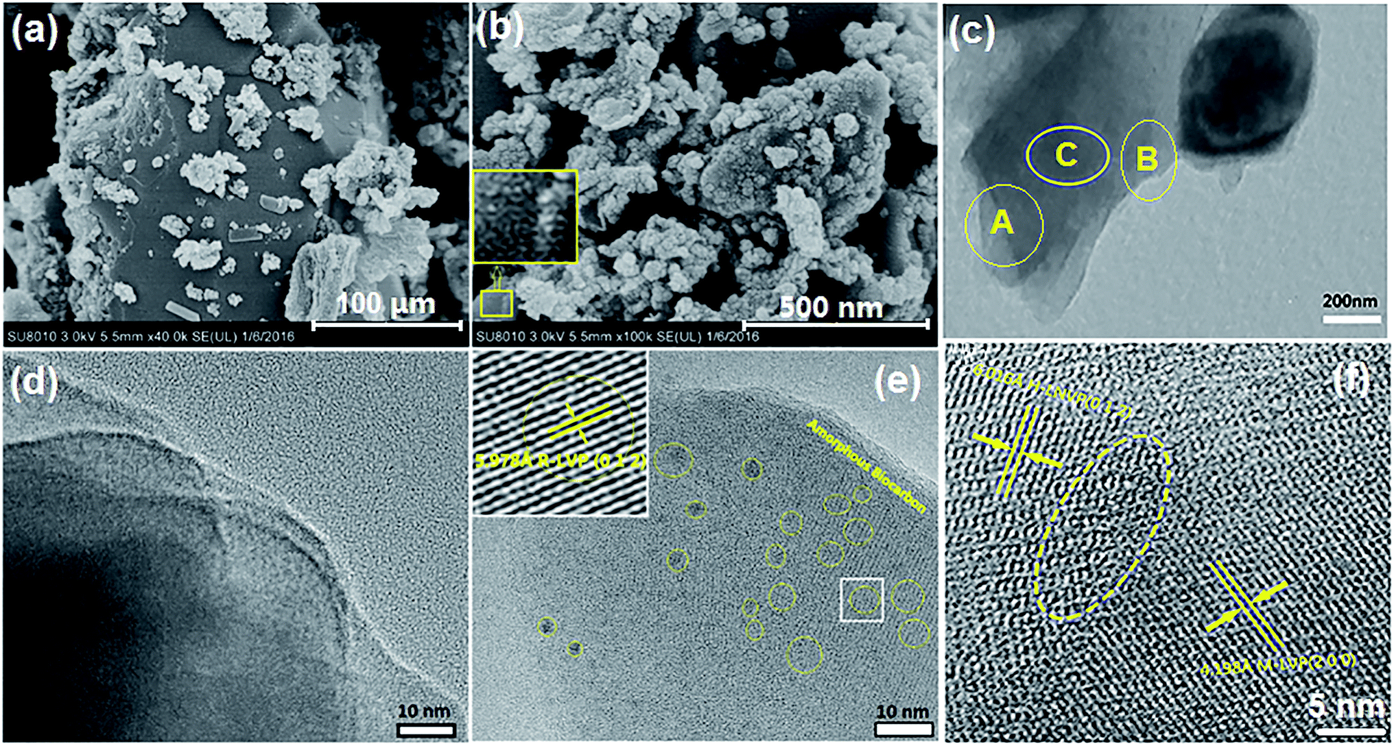 | ||
| Fig. 5 SEM (a and b) and TEM (c) images of the H-LNVP nanocomposite sample. (d) HRTEM image of selected A region in (c), (e) HRTEM image of selected B region in (c), (f) HRTEM image of selected C region in (c). | ||
3.3 Electrochemical properties
Fig. 6a shows the initial charge–discharge curves of H-LNVP, LNVP and LVP at 0.1C rate in the potential of 2.0–4.3 V (vs. Li/Li+), respectively. Unlike the LVP with three voltage plateaus and LNVP with one voltage plateau, the initial charge–discharge curves of H-LNVP show four well-defined plateaus. One main plateau at 3.78/3.72 V is corresponding to the extraction/insertion of Li+ ion in the rhombohedral phase and three charge/discharge plateaus at 3.61/3.55, 3.70/3.61 and 4.09/4.04 V are corresponding to the extraction/insertion of Li+ ion in the monoclinic phase. The initial discharge specific capacity of H-LVP is 158 mA h g−1, far better than the LNVP and pure LVP sample. Fig. 6b shows that the initial discharge capacity of pure LVP is about 120, 115, 110, 100, 74 and 30 mA h g−1 at 0.1, 0.2, 0.5, 1, 5 and 10C, respectively. The initial discharge capacity of LNVP show in Fig. 6c is about 110, 106, 100, 90, 74 and 60 mA h g−1 at 0.1, 0.2, 0.5, 1, 2 and 10C, respectively. Compared with LNVP and LVP, the initial discharge capacity of H-LNVP (Fig. 6d) is about 158, 142, 130, 120, 110 and 90 mA h g−1 at 0.1, 0.2, 0.5, 2, 1 and 10C respectively, which is much higher than that of the LNVP and LVP electrode. To evaluate the rate capability, H-LNVP electrodes are cycled at various current densities from 0.1C to 10C over a voltage window of 2.0–4.3 V (Fig. 6e). Even compared with previous reports of H-LNVP by Tang et al.24 and Zhang et al.26 (119.1 mA h g−1 was delivered at 0.05C rate and 80 mA h g−1 was exhibited at 5C for the LNVP, respectively), the H-LNVP prepared in our work exhibits the higher rate performance. Recently, Mao et al.25 synthesised high performance hybrid phase Li2NaV2(PO4)3 (H-LNVP), which can deliverer a discharge capacity of 123.3 mA h g−1 at 0.5C rate. But the coulombic efficiency is 96.41% at 0.5C rate and decays to 89.87% at 5C rate. Although the specific capacity of the H-LNVP synthesised in our work gradually decreases with the increasing current rates, a high coulombic efficiency close to 98% has been achieved at different rates and very close to 100% at 10C. These results indicate that the introduction of ATP not only changes the phase composition but also greatly improves the electrochemical properties of the synthetic samples. After 100 cycles at 10C, the H-LNVP cathode synthesized still delivered a high capacity of 84.6 mA h g−1, retained 94.6% of its initial capacity (Fig. 6f).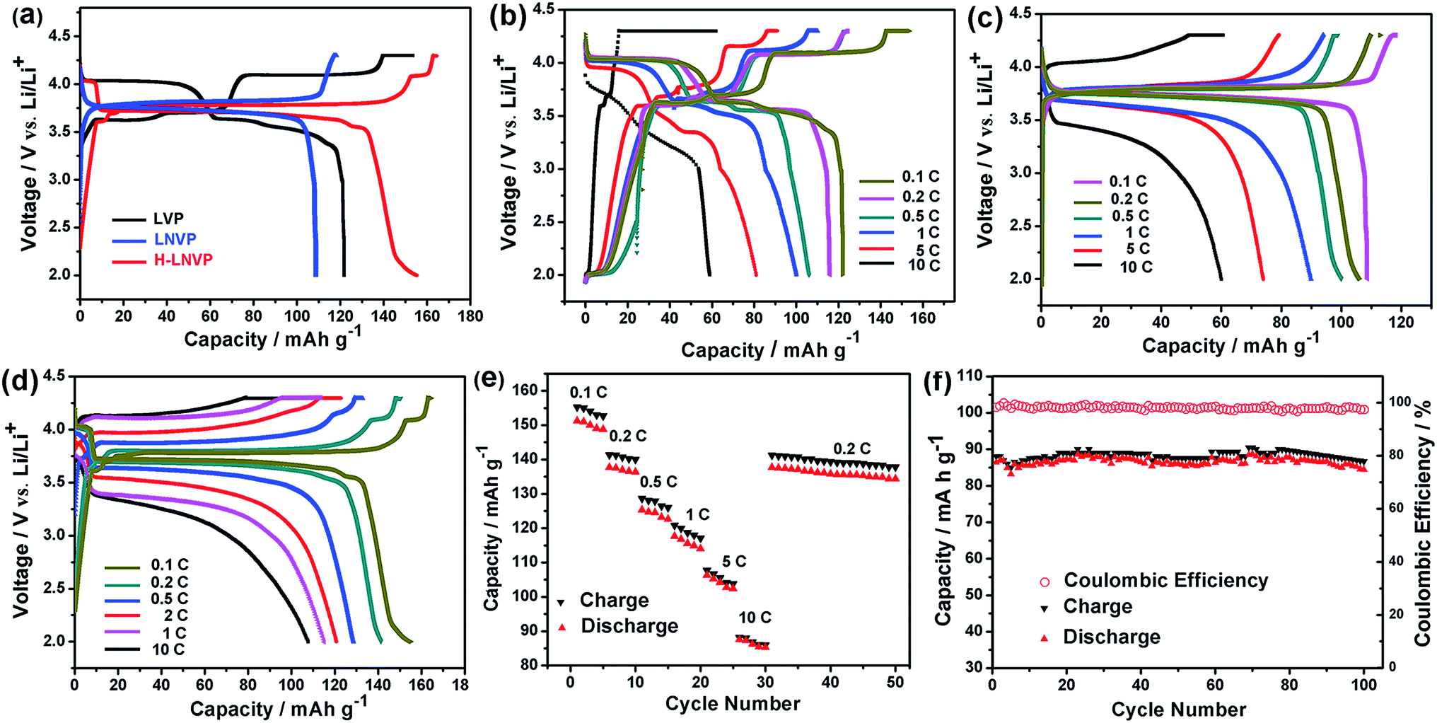 | ||
| Fig. 6 (a) The initial charge–discharge curves of pure LVP, LNVP and H-LNVP at 0.1C. (b) The initial charge–discharge curves of pure LVP at different rates. (c) The initial charge–discharge curves of pure LNVP at different rates. (d) The initial charge–discharge curves of H-LNVP at different rates. (e) Capacity retention of the H-LNVP cathodes. (f) The cycling performance and the coulombic efficiency of H-LNVP-C at 10C. | ||
Fig. 7a displays the CV curves for the LVP, LNVP and H-LNVP at scan rates of 0.1 mV s−1. For the LVP∥Li half cells, we can clearly distinguish that three oxidation peaks are located at 3.62, 3.71 and 4.13 V, which are consistent with the three plateaus in the charge curve of M-LVP shown in Fig. 6a. The corresponding phase transition process is: Li3V2(PO4)3 ⇔ Li2.5V2(PO4)3 ⇔ Li2V2(PO4)3 ⇔ LiV2(PO4)3. For LNVP, only a couple of reversible redox peaks at 4.02 V and 3.62 V can be observed, assigning to the V3+/V4+ redox reaction. For H-LNVP, we can clearly distinguish that four oxidation peaks are located around 3.62, 3.71, 4.0 and 4.13 V. However, there are only two reduction peaks appear around 4.0 and 3.5 V can be observed. The redox behaviors of H-LNVP are quite different with those of LVP and LNVP, which indicates that the lithiation/delithiation behaviors of H-LNVP correspond to the hybrid phase transition process: Li2NaV2(PO4)3 ⇔ NaV2(PO4)3 and Li3V2(PO4)3 ⇔ LiV2(PO4)3. EIS was carried out after 70 cycles at 10C and a charge of 4.3 V to investigate the electrochemical kinetic properties of the different samples. Fig. 7b shows the Nyquist plots of the different samples and an equivalent circuit model is shown in the inset for the analysis of the impedance spectra. The charge transfer resistance (Rct) value of the LVP, LNVP and H-LNVP samples are 325 Ω, 103 Ω and 85.8 Ω, respectively. These results indicate that the electrons can be transferred more easily between H-LNVP particles and the electrolyte due to the existence of the carbon layer and quantum dots. The conductivity values σ are calculated from eqn (1):38
 | (2) |
| Ip = 2.69 × 10⁵An3/2CoD1/2v1/2 | (3) |
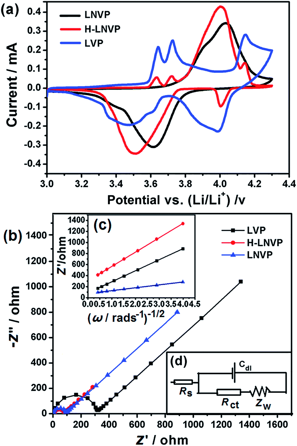 | ||
| Fig. 7 (a) The CV curves of pure LVP, LNVP and H-LNVP at a scan rate of 0.1 mV s−1 in the voltage range of 3.0–4.3 V. (b) Nyquist plots of the different cathodes after 70 cycles at 10C and a charge of 4.3 V. (c) Relationship plot of impedance as a function of the inverse square root of the angular frequency in the Warburg region. (d) The equivalent circuit model of the cell assembled with H-LNVP. | ||
The equivalent circuit model is shown in Fig. 7d. In the equivalent circuit, Rs (the intercept of the high frequency region in Fig. 7b) represents the ohmic resistance of whole reaction system, which includes the interparticle contact resistance, electrolyte resistance and other physical resistances between the electrolyte and electrode; Rct (the radius of the semicircle at high frequency region on the Zreal-axis in Fig. 7b) stands for charge transfer resistance between the electrode and the electrolyte; Cdl is the double layer capacitance on the electrode surface; and Zw (the slope of inclined line in low frequency) is the diffusion-controlled Warburg impedance associated with solid state diffusion.39
According to Goodenough et al.41 and Xiaobo Ji et al.42 works, R-LNVP could be reasonably formed from NVP by ion exchange with Li ions. In the crystal structure of NVP, the “lantern” units [V2(PO4)3]3− aligned along the c axis and form a three-dimensional framework structure. Each “lantern” unit contains one A1 site occupied by Na ion and two A2 sites occupied by two Na ions. The two Na ions at the two A2 sites could be exchanged by two Li ions to form R-LNVP, while the Na+ ion at A1 site is maintained the original position. In the H-LNVP sample Na+ ion introduced by Na2ATP occupies the one A1 site because of it's more suitable radius at this site. The Li+/Na+ hybrid ions at two A2 sites can be extracted/inserted reversible during the charge–discharge process. The possible ion insertion/extraction mechanism of the H-LNVP sample as cathode for LIBs can be suggested as following:40
| Li3V2(PO4)3 ↔ Li3−xV2(PO4)3 + xe− + xLi+ | (4) |
| Na(A1)Na2(A2)V2(PO4)3 + xe− ↔ Na(A1)Na2−x(A2)V2(PO4)3 + xNa+ | (5) |
| Na(A1)Na2−x(A2)V2(PO4)3 + yNa+ + (x − y)Li+ ↔ Lix−yNa(A1)Na2−x+y(A2)V2(PO4)3 | (6) |
The storage (or release) of Li+ takes place at both the anode and cathode, and the release (or storage) of Na+ occurs only at the cathode. The ion insertion/extraction process involves the immigration of ion between the electrolytes and electrode, the reversible Li and Na adsorption and Li+/Na+ ion exchange when the H-LNVP/CD nanocomposites are in contact with the electrolyte. During charging and discharging, the total concentration of Li and Na is fixed to ensure the charge neutrality of the electrolytes, but the Li+/Na+ ratio is changed.39
4. Conclusions
In summary, the layered hybrid phase Li2NaV2(PO4)3/carbon dot (H-LNVP/CD) nanocomposite has been synthesized via a sol–gel method and carbon thermal reduction method. This composite is composed of hybrid phases of rhombohedral Li3V2(PO4)3, rhombohedral Li2NaV2(PO4)3 and monoclinic Li3V2(PO4)3, biocarbon carbon matrix and carbon dots (CDs). On the one hand, the introduction of Na2ATP enhances the conductivity of the material though the formation of biocarbon layer substrate and carbon dots. On the other hand, the sodium ion not only promotes the phase transformation but also improves the specific discharge capacity. The nanocomposite cathode exhibits a high reversible discharge capacity of 158 mA h g−1 at 0.1C and excellent cycling stability at 10C. The reversible capacity can retained 97.6% after 50 cycles at various current densities and a high coulombic efficiency close to 100% at 10C can be obtained. Potentially, our approach could also be applied in synthesizing other types of cathode materials.Acknowledgements
The authors thank Natural Science Foundation of China (Grant No. 51472127, 51272144 and 51672139) for the financial support.Notes and references
- D. Saikia, T.-H. Wang, C.-J. Chou, J. Fang, L.-D. Tsai and H.-M. Kao, RSC Adv., 2015, 5, 42922–42930 RSC.
- D. Wang, Y. Yu, H. He, J. Wang, W. Zhou and H. D. Abruña, ACS Nano, 2015, 9, 1775–1781 CrossRef CAS PubMed.
- J. Feng, Z. Zhang, L. Ci, W. Zhai, Q. Ai and S. Xiong, J. Power Sources, 2015, 287, 177–183 CrossRef CAS.
- Y.-L. Ding, Y. Wen, C. Wu, P. A. van Aken, J. Maier and Y. Yu, Nano Lett., 2015, 15, 1388–1394 CrossRef CAS PubMed.
- Y. Zhao, X. Li, B. Yan, D. Li, S. Lawes and X. Sun, J. Power Sources, 2015, 274, 869–884 CrossRef CAS.
- J. Wang and X. Sun, Energy Environ. Sci., 2015, 8, 1110–1138 CAS.
- G. Jeong, Y.-U. Kim, H. Kim, Y.-J. Kim and H.-J. Sohn, Energy Environ. Sci., 2011, 4, 1986–2002 CAS.
- Z. Ma, X. Yuan, L. Li, Z.-F. Ma, D. P. Wilkinson, L. Zhang and J. Zhang, Energy Environ. Sci., 2015, 8, 2144–2198 CAS.
- X. Zhang, R.-S. Kühnel, H. Hu, D. Eder and A. Balducci, Nano Energy, 2015, 12, 207–214 CrossRef CAS.
- Y. Li, W. Bai, Y. Zhang, X. Niu, D. Wang, X. Wang, C. Gu and J. Tu, J. Power Sources, 2015, 282, 100–108 CrossRef CAS.
- Z. Jinli, W. Jiao, L. Yuanyuan, N. Ning, G. Junjie, Y. Feng and L. Wei, J. Mater. Chem. A, 2015, 3, 2043–2049 Search PubMed.
- K. Naoi, K. Kisu, E. Iwama, Y. Sato, M. Shinoda, N. Okita and W. Naoi, J. Electrochem. Soc., 2015, 162, A827–A833 CrossRef CAS.
- W. Li, Y. Yang, G. Zhang and Y.-W. Zhang, Nano Lett., 2015, 15, 1691–1697 CrossRef CAS PubMed.
- L.-H. Tai, Q. Zhao, L.-Q. Sun, L.-N. Cong, X.-L. Wu, J.-P. Zhang, R.-S. Wang, H.-M. Xie and X.-H. Chen, New J. Chem., 2015, 39, 9617–9626 RSC.
- W.-F. Mao, Y.-B. Fu, H. Zhao, G. Ai, Y.-L. Dai, D. Meng, X.-H. Zhang, D. Qu, G. Liu and V. S. Battaglia, ACS Appl. Mater. Interfaces, 2015, 7, 12057–12066 CAS.
- X. You, S. Xiao, T. Zhang, D. Zeng, Q. Xiao, Z. Li and G. Lei, Mater. Technol., 2015, 30, A64–A69 CrossRef CAS.
- P. Li, L. Shao, P. Wang, X. Zheng, H. Yu, S. Qian, M. Shui, N. Long and J. Shu, Electrochim. Acta, 2015, 180, 120–128 CrossRef CAS.
- Y. Cheng, K. Feng, W. Zhou, H. Zhang, X. Li and H. Zhang, Dalton Trans., 2015, 44, 17579–17586 RSC.
- Y. Zhang, P. Nie, L. Shen, G. Xu, H. Deng, H. Luo and X. Zhang, RSC Adv., 2014, 4, 8627–8631 RSC.
- B. L. Cushing and J. B. Goodenough, J. Solid State Chem., 2001, 162, 176–181 CrossRef CAS.
- W. Song, X. Ji, Y. Yao, H. Zhu, Q. Chen, Q. Sun and C. E. Banks, Phys. Chem. Chem. Phys., 2014, 16, 3055–3061 RSC.
- W. Song, X. Ji, C. Pan, Y. Zhu, Q. Chen and C. E. Banks, Phys. Chem. Chem. Phys., 2013, 15, 14357–14363 RSC.
- J. Liu, K. Tang, K. Song, P. A. van Aken, Y. Yu and J. Maier, Nanoscale, 2014, 6, 5081–5086 RSC.
- Y. Tang, C. Wang, J. Zhou, Y. Bi, Y. Liu, D. Wang, S. Shi and G. Li, J. Power Sources, 2013, 227, 199–203 CrossRef CAS.
- W.-F. Mao, Y. Ma, S.-K. Liu, Z.-Y. Tang and Y.-B. Fu, Electrochim. Acta, 2014, 147, 498–505 CrossRef CAS.
- Y. Zhang, P. Nie, L. Shen, G. Xu, H. Deng, H. Luo and X. Zhang, RSC Adv., 2014, 4, 8627–8631 RSC.
- P. Li, L. Shao, P. Wang, X. Zheng, H. Yu, S. Qian, M. Shui, N. Long and J. Shu, Electrochim. Acta, 2015, 180, 120–128 CrossRef CAS.
- J.-N. Chotard, G. Rousse, R. David, O. Mentré, M. Courty and C. Masquelier, Chem. Mater., 2015, 27, 5982–5987 CrossRef CAS.
- V. Aravindan, J. Sundaramurthy, P. S. Kumar, Y.-S. Lee, S. Ramakrishna and S. Madhavi, Chem. Commun., 2015, 51, 2225–2234 RSC.
- H. Zhao, Y. Wei, R. Qiao, C. Zhu, Z. Zheng, M. Ling, Z. Jia, Y. Bai, Y. Fu and J. Lei, Nano Lett., 2015, 15, 7927–7932 CrossRef CAS PubMed.
- C. Wei, W. He, X. Zhang, S. Liu, C. Jin, S. Liu and Z. Huang, RSC Adv., 2015, 5, 28662–28669 RSC.
- X. Zhang, Z. Bi, W. He, G. Yang, H. Liu and Y. Yue, Energy Environ. Sci., 2014, 7, 2285–2294 CAS.
- J. Zhang, W. Sun, L. Yin, X. Miao and D. Zhang, J. Mater. Chem. C, 2014, 2, 4812–4817 RSC.
- N. Paul, E. Metwalli, Y. Yao, M. Schwartzkopf, S. Yu, S. V. Roth, P. Müller-Buschbaum and A. Paul, Nanoscale, 2015, 7, 9703–9714 RSC.
- V. Biju, Chem. Soc. Rev., 2014, 43, 744–764 RSC.
- K. Zhao, Z. Pan, I. Mora-Seró, E. Cánovas, H. Wang, Y. Song, X. Gong, J. Wang, M. Bonn and J. Bisquert, J. Am. Chem. Soc., 2015, 137, 5602–5609 CrossRef CAS PubMed.
- S. Jiao, Q. Shen, I. Mora-Seró, J. Wang, Z. Pan, K. Zhao, Y. Kuga, X. Zhong and J. Bisquert, ACS Nano, 2015, 9, 908–915 CrossRef CAS PubMed.
- Y. Cui, X. Zhao and R. Guo, Electrochim. Acta, 2010, 55, 922–926 CrossRef CAS.
- X. Zhang, X. Xu, W. He, G. Yang, J. Shen, J. Liu and Q. Liu, J. Mater. Chem. A, 2015, 3, 22247–22257 CAS.
- Q. An, F. Xiong, Q. Wei, J. Sheng, L. He, D. Ma, Y. Yao and L. Mai, Adv. Energy Mater., 2015, 1401963, 1–10 Search PubMed.
- B. L. Cushing and J. B. Goodenough, J. Solid State Chem., 2001, 162, 176–181 CrossRef CAS.
- W. Song, X. Ji, Y. Yao, H. Zhu, Q. Chen, Q. Sun and C. E. Banks, Phys. Chem. Chem. Phys., 2014, 16, 3055–3061 RSC.
| This journal is © The Royal Society of Chemistry 2017 |