 Open Access Article
Creative Commons Attribution 3.0 Unported Licence
High-performance all-solid-state flexible carbon/TiO2 micro-supercapacitors with photo-rechargeable capability†
Jinguang Caiab,
Chao Lvab and
Akira Watanabe*a
aInstitute of Multidisciplinary Research for Advanced Materials, Tohoku University, 2-1-1 Katahira, Aoba-ku, Sendai 980-8577, Japan. E-mail: watanabe@tagen.tohoku.ac.jp
bInstitute of Materials, China Academy of Engineering Physics, Jiangyou 621908, Sichuan, PR China
First published on 3rd January 2017
Abstract
A high-performance all-solid-state flexible interdigitated carbon/TiO2 micro-supercapacitor (MSC) with photo-rechargeable capability was prepared by combining a laser direct writing technique with electrophoretic deposition of TiO2 nanoparticles. The carbon/TiO2 MSC shows the same excellent capacitive performance as the pure carbon MSC, such as high specific capacitance up to 27.3 mF cm−2 at a typical current density of 0.05 mA cm−2, excellent cycling stability, long-time stability, and mechanical stability. Under UV light irradiation, the carbon/TiO2 MSC can be charged to above 100 mV, and still maintain 60 mV after 10 photo-charging cycles, demonstrating its photo-rechargeable capability. What's more, after 10 photo-charging cycles, the carbon/TiO2 MSC shows no capacitive performance degradation, which can be attributed to the high structural stability of the carbon/TiO2 MSC under UV light irradiation.
1. Introduction
Recently, miniaturized portable and wearable flexible electronic devices have aroused worldwide research attention, but the relatively high volume and weight of the energy supply units limit the whole size of the micro-system.1,2 Therefore, it is important to develop micro-energy storage units with small sizes and high energy and power densities, as well as integrated energy harvesting units, to make the whole micro-system self-powered. Micro-supercapacitors (MSCs) are recognized as potential power supply units for on-chip micro-devices because they possess not only the advantages of supercapacitors such as high power density, excellent cycling performance, pollution-free operation, maintenance-free features, small size, light weight, and flexibility, but also simplified packaging processes, robust all solid state, and compatibility with integrated circuits.2–7 Commercial solar panels can be used to charge the MSCs, making the system self-powered, but commercial solar panels usually have heavy weight and large size, limiting the miniaturization and portability of the system. It will be effective to integrate the micro-size energy harvest and storage units in the same compact system.8–11A promising way is to integrate the solar energy harvest and storage parts into one unit sharing the electrodes, thus realizing a self-powered photo-rechargeable energy unit.12–23 A typical solar battery consists of a photo-electrode, a charge-storage electrode, and a counter electrode. In the charging mode, the photo-electrode and charge-storage electrode are connected. After the charging, the charge-storage electrode and counter electrode are connected to drive working devices. In some previous work, only two electrodes can also realize the same functions, where an electrode works as both the photo-electrode and the charge-storage electrode.24–27 Such a system may make the photo-charge and discharge process easy and convenient. To date, most of the reports focused on the sandwich-type photo-rechargeable system, and there are rare studies on the fabrication and demonstration of the in-plane-type photo-rechargeable micro-supercapacitors, possibly due to the difficulties on the design and fabrication. An in-plane-type film cell has the advantages of thinner thickness, flexibility, simple production, and the cost in the application to wearable flexible electronic devices. Therefore, it is challenging, but important to explore the suitable materials and methods for the fabrication of such-type photo-rechargeable MSCs.
Carbon materials including carbon nanotubes, graphene, and graphite nanomaterials are recognized as good candidates for flexible high-performance MSCs because of the adaptive properties such as high conductivity, high specific surface area, electrochemical stability, and high mechanical tolerance.28–31 Many methods such as lithographic and printing techniques have been developed for the fabrication and patterning of the micro-supercapacitors.2,32–39 Compared with these methods, laser direct writing, which is a non-contact, efficient, single-step fabrication technique without requirements of masks, post-processing, and complex clean room, is a useful patterning technique,40–44 and can be easily integrated with current electronic product lines for commercial use. Laser induced carbonization from polymer films was first demonstrated for the fabrication of high-performance carbon MSCs by using high-power CO2 infrared pulse lasers and 522 nm pulse lasers.45–49 Recently, we demonstrated the fabrication of high-performance all-solid-state flexible carbon MSCs by laser direct writing on polyimide (PI) films in air using a relatively low-power compact continuous-wave blue-violet semiconductor laser with a wavelength of 405 nm, the power of which can almost be totally absorbed by the PI film.50 We further conducted the similar laser direct writing process on PI film with only changing the air to inert atmosphere with argon (Ar) gas, resulting in highly increased conductivity, specific surface area, and pore size distribution, thus greatly improved energy and power densities.51 Therefore, laser direct writing is a promising method for the fabrication of high-performance MSCs.
Titanium dioxide (TiO2) has been widely investigated due to its unique physicochemical properties and many promising applications in energy and environmental fields ranging from solar cells and lithium ion batteries to photocatalysis and sensing.52–54 TiO2 is a very useful model material for the study of photo-rechargeable batteries although it can only absorb UV light. For example, Nomiyama et al. reported the sandwich-type photo-rechargeable batteries using TiO2 nanoparticles as the main photo-absorption materials in the composite films.55–57 However, there are rare studies on the in-plane-type photo-rechargeable micro-supercapacitors. In this work, we demonstrated the fabrication of an in-plane-type two-electrode carbon/TiO2 micro-supercapacitor with photo-rechargeable capability by combining laser direct writing on a PI film in Ar with electrophoretic deposition of TiO2 nanoparticles on one electrode. The all-solid-state carbon/TiO2 MSC showed the same excellent capacitive performance with the pure carbon MSC without TiO2 deposition, such as high specific capacitance, excellent cycling stability, long-time stability, and flexibility. At the same time, this carbon/TiO2 MSC exhibited strong response to UV light and can be charged to more than 100 mV under UV irradiation. After cycling 10 times, it can still be charged to more than 60 mV without capacitive performance degradation.
2. Experimental
2.1 Preparation of photo-rechargeable micro-supercapacitors
The preparation of carbon electrodes on flexible polyimide (PI) films was conducted using the same method as previously reported.51 The commercial PI film with a thickness of 125 μm (Kapton 500H) received from Du Pont-Toray Co. Ltd. was first cleaned with water and ethanol before laser irradiation. The laser direct writing process was then carried out in an inert environment of Ar using the same experimental setup as reported in our previous work. A sample box with a quartz window for laser irradiation and a gas inlet and outlet was employed to provide an inert environment by means of an Ar gas flow. A schematic illustration of the laser writing system is shown in Fig. S1.† The laser power was fixed at a typical value of 157 mW in this work. After laser writing, the samples were rinsed with acetone and water to remove surface dust which was produced as by-products during the laser-induced carbonization. Plasma treatment of the samples was conducted by air-plasma etching for 100 s (JEOL, JFC-1500).For the preparation of carbon/TiO2 composite electrodes, laser-irradiated parts of the PI film were first connected to conductive copper tape using Ag paste in order to fabricate into a micro-cell for electrophoretic deposition of TiO2 nanoparticles. PI tape was employed to define the effective interdigitated area of the electrodes and avoid direct contact between the electrolyte and the electrode pad areas. After air-plasma etching for 100 s (JEOL, JFC-1500) to make the surface hydrophilic, 300 μL of the 6 nm TiO2 dispersion (1 wt% of an acidic anatase sol TKS201, average diameter 6 nm, TAYCA) was dropped onto the active area. The electrophoretic deposition process was conducted in a two-electrode electrochemical system under a voltage of 3 V for 3 h. After deposition, the active area was cleaned with deionized (DI) water and dried in air. PVA/H2SO4 polymer electrolyte was prepared by stirring 1 g of poly(vinyl alcohol) (PVA, Mw = 89![[thin space (1/6-em)]](https://www.rsc.org/images/entities/char_2009.gif) 000–98
000–98![[thin space (1/6-em)]](https://www.rsc.org/images/entities/char_2009.gif) 000, Sigma-Aldrich) in 10 mL of DI water and 1 mL of sulfuric acid (98%, Sigma-Aldrich) for 4 hours at 95 °C. The micro-supercapacitors with photo-rechargeable capability were fabricated by dropping the PVA–H2SO4 electrolyte (150 μL) onto the active area on the PI substrate and removing excess water by placing the substrate overnight in a desiccator connected to a vacuum pump.
000, Sigma-Aldrich) in 10 mL of DI water and 1 mL of sulfuric acid (98%, Sigma-Aldrich) for 4 hours at 95 °C. The micro-supercapacitors with photo-rechargeable capability were fabricated by dropping the PVA–H2SO4 electrolyte (150 μL) onto the active area on the PI substrate and removing excess water by placing the substrate overnight in a desiccator connected to a vacuum pump.
2.2 Characterization
The samples were characterized by scanning electron microscopy (SEM, Hitachi S4800, 10 kV), transmission electron microscopy (TEM, JEOL 2010), and X-ray photoelectron spectroscopy (XPS, Perkin Elmer PHI5600). Raman spectra were measured on a micro-Raman spectrometer equipped with an optical microscope (Olympus BX51), a 532 nm DPSS CW laser (MGL-H-532 nm-1W, CNI), a CCD camera (DV401, Andor Technology), and a monochromator (MS257, Oriel Instruments Co.). The samples for TEM measurement were powders scraped from laser written films. Other characterizations were conducted directly on the films. X-ray diffraction pattern of TiO2 nanoparticles was collected using a diffractometer (Rigaku Rint-Ultima III) with Cu Kα (λ = 1.54187 Å) radiation.2.3 Electrochemical measurements of micro-supercapacitors
Cyclic voltammetry (CV) and galvanostatic charge–discharge (CC) measurements were carried out using an electrochemical workstation (HZ-5000, Hokuto Denko Ltd.) and a DC Voltage and Current Source Monitor 6241A (ADCMT Corporation), respectively. Electrochemical impedance spectra measurements were conducted using a Hioki 3522 LCR HiTESTER over a frequency range from 10 mHz to 100 kHz. For the bending experiments, an MSC was fixed on a series of stainless steel tubes with various curvatures before CV curves were measured.The calculation of the specific capacitances (CA, mF cm−2) of the MSCs from the CV curves was based on the following equation:51
 | (1) |
 is the numerically integrated area of the CV curve.
The calculation of the specific capacitances (CA, mF cm−2) of the MSCs from the CC curves was based on the following equation:51
 | (2) |
2.4 Photo-rechargeable capability measurements of carbon/TiO2 micro-supercapacitors
Two-electrode electrochemical system was employed to measure the photo-rechargeable capability of the carbon/TiO2 MSC with positive electrode and negative electrode connected to carbon/TiO2 electrode and opposite carbon electrode, respectively. The UV light was provided by a 150 W xenon lamp (L2274, HAMAMATSU) with a UV transmitting filter (UTVAF-50S-33U, SIGMA KOKI Japan), and a PC-controlled shutter unit (F77-6, SURUGA SEIKI) was used to switch the light on and off.3. Results and discussion
3.1 Morphology and structure
A schematic illustration of the fabrication process for the carbon/TiO2 composite electrode is shown in Fig. 1. The interdigitated carbon electrodes were first fabricated by laser direct writing on a clean polyimide (PI) film in Ar at a typical laser power of 157 mW. The carbon electrodes were then connected to the external circuits with Cu tape and Ag paste, which are protected by PI tape to avoid the contact between electrodes and electrolyte. Air-plasma etching was employed to modify the surface wettability of the carbon electrodes from hydrophobic to superhydrophilic. After 300 μL of the TiO2 dispersion (1 wt%) dropped onto the active area, the electrophoretic deposition process was conducted in a two-electrode electrochemical system under a voltage of 3 V for 3 h. It should be noted that as-received TiO2 nanoparticles are anatase phase and have a diameter less than ten nanometers, which are also confirmed by the XRD pattern and TEM image (Fig. S2†). After deposition, the electrodes were cleaned with DI water and PVA/H2SO4 electrolyte (150 μL) was dropped onto the active area on the PI substrate. After removing excess water by placing the substrate overnight in a desiccator connected to a vacuum pump, the all-solid-state asymmetric MSC with one carbon/TiO2 electrode and one carbon electrode was prepared successfully. | ||
| Fig. 1 Schematic illustration for the fabrication of a carbon/TiO2 micro-supercapacitor with photo-rechargeable capability. | ||
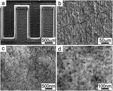
The carbon layer obtained by laser direct writing in Ar at a typical laser power of 157 mW before electrophoretic deposition of TiO2 nanoparticles shows the same structures with our previous work, exhibiting a smooth surface with many internal nano- and micro-pores and a thickness of about 12 μm (Fig. S3†). The areal loading of the carbon materials is about 0.8 mg cm−2, which was calculated by weighing the carbon powder scraped from the laser-writing parts. The current curve during the electrophoretic deposition process is shown in Fig. S4.† It should be noted that hydrogen and oxygen gases are evolved from the electrodes during the electrophoretic deposition process because of the relatively high voltage. Fig. 2 shows the SEM images of the sample after electrophoretic deposition of TiO2 nanoparticles. In Fig. 2a, the top dark branch is the negative electrode, on which there are only few TiO2 nanoparticles on the surface because of the physical adsorption. Compared with the negative electrode, the positive electrode of the bottom branch became relatively bright in the SEM image. It also shows a smooth surface although there are some cracks due to stress in the carbon structures (Fig. 2b). An enlarged SEM image in Fig. 2c indicates a thick layer of TiO2 nanoparticles on the surface. The high-resolution SEM image in Fig. 2d clearly shows the TiO2 nanoparticles on the surface. The thickness of the TiO2 layer was less than 200 nm from the cross-sectional SEM image although the exact determination of the thickness is difficult because of the rough surface of the porous carbon layer. Considering the average size of TiO2 nanoparticles from TEM image (ca. 6 nm), the areal loading of the TiO2 layer was estimated to be less than 0.06 mg cm−2, which is ten times lower than that of the carbon layer.
The typical Raman spectra of carbon structures and carbon/TiO2 composites are shown in Fig. 3a. The Raman peaks at 1350 cm−1 and 1580 cm−1 observed in both samples are corresponded to the D band and G band for graphitized or amorphous carbon materials, but the intensity for carbon/TiO2 composite structures was suppressed largely due to the cover of TiO2 nanoparticles. The Raman peaks at 161, 407, 519, and 638 cm−1 in carbon/TiO2 composite electrodes can be assigned as the Eg, B1g, B1g or A1g, Eg modes of the anatase phase, respectively,58 thus confirming the deposition of TiO2 nanoparticles on the carbon surface. XPS spectra in Fig. 3b indicate the carbon peaks were greatly reduced and the Ti and O peaks become dominated, further demonstrating the formation of TiO2-on-carbon composite structures. Therefore, the carbon/TiO2 electrode can be facilely prepared by combining laser direct writing technique with electrophoretic deposition of TiO2 nanoparticles.
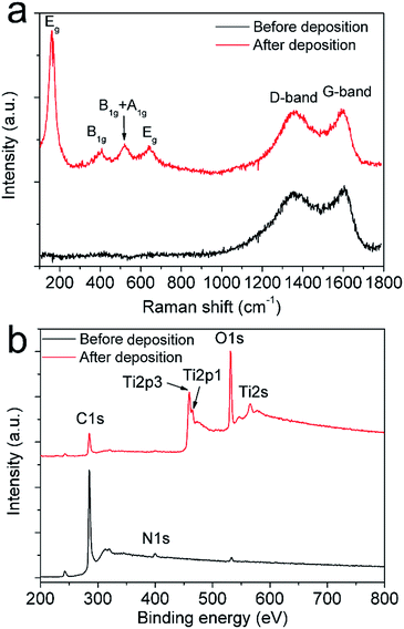 | ||
| Fig. 3 Raman (a) and XPS spectra (b) of the structures before and after electrophoretic deposition of TiO2 nanoparticles. | ||
3.2 Capacitive performance of the carbon/TiO2 micro-supercapacitor
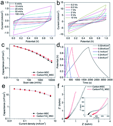
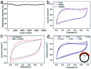
After electrophoretic deposition of TiO2 nanoparticles, PVA/H2SO4 electrolyte was dropped onto the active area and dried, forming an asymmetric MSC with a carbon/TiO2 electrode and pure carbon electrode (Fig. S5†). The electrochemical performance of the carbon/TiO2 MSC was first evaluated by cyclic voltammetry (CV) and galvanostatic charge–discharge (CC) measurements. Fig. 4a shows the CV curves at low scan rates for the typical carbon/TiO2 MSC prepared by laser direct writing in Ar at 157 mW with air-plasma treatment for 100 s and electrophoretic deposition of TiO2 nanoparticles at 3 V for 3 h, which exhibit stable quasi-rectangular shapes, indicating electrochemical double-layer (EDL) capacitive properties. The CV curves at relatively high scan rates also suggest apparent EDL capacitive properties (Fig. 4b). Fig. 4c plots the specific areal capacitances (CA) calculated from the CV curves as a function of scan rate. The CA at a typical scan rate of 10 mV s−1 is 15.5 mF cm−2, which is comparable with the 16 mF cm−2 for the pure carbon electrodes. The carbon/TiO2 MSC shows a little lower capacitance than pure carbon electrodes at low scan rates, but higher capacitances at high scan rates. The CC curves of the carbon/TiO2 electrode are shown in Fig. 4d, all of which exhibit capacitive triangular shapes. The corresponding CA values calculated from the CC curves as a function of current density is shown in Fig. 4e. The typical capacitance at a current density of 0.05 mA cm−2 is 27.3 mF cm−2, which is a little lower than the 28.8 mA cm−2 for pure carbon MSC with air-plasma treatment. The carbon/TiO2 MSC shows a little lower specific capacitance with the pure carbon MSC at low current densities, but higher capacitances at high current densities (Fig. 4e). It should be noted that the typical capacitances calculated from either CV curve or CC curve are higher than those for most of the MSCs based on carbon materials, even for carbon nanotubes and graphene. The electrochemical impedance spectra (EIS) of both carbon/TiO2 MSC and pure carbon MSC are shown in Fig. 4f. The relatively vertical slope of the Nyquist plot for carbon/TiO2 MSC in the low-frequency region suggests better capacitive behaviour than pure carbon MSC. Although the intercept on the real axis for carbon/TiO2 MSC is 123 Ω, higher than the 52 Ω for pure carbon MSC, indicating that carbon/TiO2 MSC has a larger equivalent series resistance, a shorter Warburg region and smaller diameter semicircle in the high- and mid-frequency regions for carbon/TiO2 MSC suggest a lower charge-transfer resistance and a more efficient ion diffusion process than those for pure carbon MSC. Therefore, the carbon/TiO2 MSC exhibits a comparable capacitive performance with pure carbon MSC.The cycling stability, long-time stability, and mechanical stability were studied, which are very important for practical use. The cycling stability of carbon/TiO2 MSC was measured over 10![[thin space (1/6-em)]](https://www.rsc.org/images/entities/char_2009.gif) 000 CV cycles at a scan rate of 50 mV s−1, showing no capacitance degradation (Fig. 5a). The excellent cycling stability can be ascribed to the high stability of the carbon/TiO2 electrode and the interface between the electrode and the electrolyte. The small change of the CV shapes after the cycling measurement may imply that the interface between carbon/TiO2 electrodes and the electrolyte became more stable and capacitive with cycling scan (Fig. 5b). Surprisingly, the carbon/TiO2 MSC shows an increase specific capacitance and a more capacitive behaviour even after 3 months kept in air (Fig. 5c), which is much better than the MSC based on multi-walled carbon nanotubes with PVA/H3PO4 electrolyte.59 This result suggests that the carbon/TiO2 layered hybrid structures are very stable under the acidic condition and the MSC becomes more capacitive due to the osmosis of electrolyte through the pores in the carbon electrode. The mechanical stability of a typical carbon/TiO2 MSC was evaluated by bending the MSC tightly on a series of stainless steel tubes with different diameters. The CV curves in Fig. 5d indicate similar capacitive shapes with no apparent capacitance degradation, even for the MSC bent to a curvature radius of 3 mm and folded 180 degrees, suggesting an excellent flexibility and mechanical stability. Therefore, the carbon/TiO2 MSC shows excellent cycling stability, long-time stability, and flexibility.
000 CV cycles at a scan rate of 50 mV s−1, showing no capacitance degradation (Fig. 5a). The excellent cycling stability can be ascribed to the high stability of the carbon/TiO2 electrode and the interface between the electrode and the electrolyte. The small change of the CV shapes after the cycling measurement may imply that the interface between carbon/TiO2 electrodes and the electrolyte became more stable and capacitive with cycling scan (Fig. 5b). Surprisingly, the carbon/TiO2 MSC shows an increase specific capacitance and a more capacitive behaviour even after 3 months kept in air (Fig. 5c), which is much better than the MSC based on multi-walled carbon nanotubes with PVA/H3PO4 electrolyte.59 This result suggests that the carbon/TiO2 layered hybrid structures are very stable under the acidic condition and the MSC becomes more capacitive due to the osmosis of electrolyte through the pores in the carbon electrode. The mechanical stability of a typical carbon/TiO2 MSC was evaluated by bending the MSC tightly on a series of stainless steel tubes with different diameters. The CV curves in Fig. 5d indicate similar capacitive shapes with no apparent capacitance degradation, even for the MSC bent to a curvature radius of 3 mm and folded 180 degrees, suggesting an excellent flexibility and mechanical stability. Therefore, the carbon/TiO2 MSC shows excellent cycling stability, long-time stability, and flexibility.
3.3 Photo-rechargeable capability of the carbon/TiO2 micro-supercapacitor
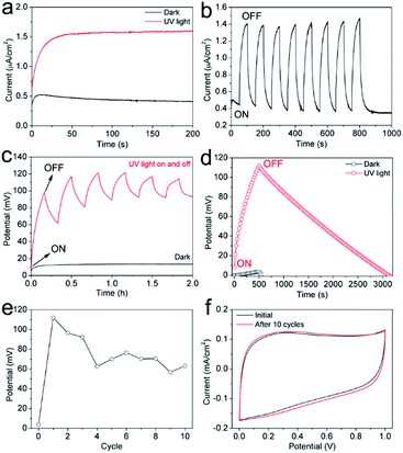
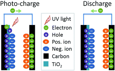
The evaluation for the photo-rechargeable capability of the carbon/TiO2 MSC was carried out using an electrochemical workstation in dark and under UV light irradiation. The UV light was provided by a Xe lamp with a UV transmitting filter (UTVAF-50S-33U, Sigmakoki, Japan), and a shutter was employed to control the light on and off. Fig. 6a shows the current density of the typical carbon/TiO2 electrode in dark and under UV light irradiation. The MSC in dark shows a current of about 0.5 μA cm−2 at first and it gradually decreased, which can be attributed to the slow balance process of the potential difference between the carbon/TiO2 electrode and the opposite carbon electrode. Under UV light irradiation, the MSC exhibits a stable current of about 1.6 μA cm−2, three times of the 0.5 μA cm−2 in dark, suggesting a photocurrent induced by the UV light irradiation. Fig. 6b shows the current changes of the carbon/TiO2 MSC when the UV light was switched on or off, which exhibits a fast and stable response to UV light. The potential change between two electrodes was also monitored when the UV light was on or off. As shown in Fig. 6c, the carbon/TiO2 MSC in dark shows a low potential of about 13 mV due to the interfacial potential difference between two electrodes. On the other hand, when the UV light turned on, the potential was increased to more than 100 mV within 10 min. If the light turned off, the potential was dropped gradually due to the self-discharge, indicating that the potential also shows fast and stable response to the UV light. Fig. 6d shows the potential change curve of the carbon/TiO2 MSC during the charge process under UV light irradiation without external applied current for 500 s and discharge process at a current density of 1 μA cm−2. Compared with the control potential change curve without UV light irradiation, the carbon/TiO2 MSC shows a much higher potential, suggesting the photo-chargeable capability of the carbon/TiO2 MSC. The cycling properties were also studied. As shown in Fig. 6e, the carbon/TiO2 MSC can still be charged to more than 60 mV under UV light after 10 cycles, indicating a photo-rechargeable capability. The voltage decay in the initial several cycles may be caused by the TiO2/electrolyte interface change due to ion diffusion after UV light irradiation, and the interface gradually became stable after several photo-charging cycles. It should be noted that the capacitive performance shows no degradation after 10 cycles, suggesting the stability of the carbon/TiO2 MSC structures under UV light (Fig. 6f).A tentative photo-charging mechanism was proposed as shown in Fig. 7. When the UV light is switched on, the TiO2 nanoparticles absorb the UV light and the valence electrons are excited to the conduction band. Then the exited electrons are transferred to the underneath carbon electrode and then to the opposite carbon electrode, finally stored in the interface between carbon structures and electrolyte in the manner of electrochemical double-layer; while the holes may be stored at the interface between TiO2 nanoparticles and the electrolyte in the same manner or transferred to the electrolyte. In the discharge state, the electrons stored in the carbon electrode will move back to the carbon/TiO2 electrode to drive the external circuit. Therefore, we demonstrated a new in-plane-type carbon/TiO2 micro-supercapacitor with photo-rechargeable capability by combining laser direct writing technique for patterning carbon electrodes with electrophoretic deposition of TiO2 nanoparticles, although the performance is capable of improvement. The relatively low voltage charged by UV light irradiation may be due to the thin thickness of the TiO2 nanoparticle film limited by the electrophoretic deposition. On one hand, the low areal amount of TiO2 nanoparticles leads to insufficient absorption of UV light, thus the relatively low voltage. In addition, the low areal amount of TiO2 nanoparticles cannot provide enough surface area to store the photo-generated holes. Therefore, with increase of the thickness of the TiO2 layer by other methods such as drop casting followed by laser patterning or electrochemical deposition, more UV light may be absorbed and stored, thus the MSC can be charged to a higher potential. Besides, other visible-light-absorption materials or combination systems which can absorb visible light, may store more photo energy effectively. Therefore, it can be expected that with careful design for structures and materials the high-performance photo-rechargeable micro-supercapacitors can be patterned by the laser direct writing technique followed by the selective deposition methods such as electrochemical deposition or layer-by-layer laser direct writing method.
4. Conclusion
We demonstrated the fabrication of high-performance carbon/TiO2 micro-supercapacitors with photo-rechargeable capability by combining laser direct writing on polyimide film in Ar with electrophoretic deposition of TiO2 nanoparticles. The carbon/TiO2 MSC exhibits a comparable capacitive performance as pure carbon MSC, showing a typical specific capacitance of 27.3 mF cm−2 at a current density of 0.05 mA cm−2, excellent cycling stability, long-time stability, as well as mechanical stability. The carbon/TiO2 MSC can be charged to above 100 mV under UV light irradiation, and still keep 60 mV after 10 photo-charging cycles, demonstrating the photo-rechargeable capability. Although the photo-chargeable performance of this new type device was capable of improvement, it is expected that this work can provide some thoughts for the fabrication of high-performance photo-rechargeable micro-supercapacitors, even totally self-powered in-plane-type flexible systems.Acknowledgements
This work was supported by a Grant-in-Aid for Scientific Research on Innovative Areas “New Polymeric Materials Based on Element Blocks (No. 2401)” (JSPS KAKENHI Grant Number JP24102004) and JSPS KAKENHI Grant Number JP15H04132, National Natural Science Foundation of China (No. 21603201), China Academy of Engineering Physics (item no. TP201302-3), and the Fundamental Application Research of the Department of Science and Technology of Sichuan Province (Grant no. 2014JY0137). The authors thank Mr Eiji Aoyagi of the Electron Microscopy Center in Tohoku University for help with the SEM and TEM measurements. The authors also thank Ms Sayaka Ogawa for help with the XPS measurement.References
- B. C. Kim, J.-Y. Hong, G. G. Wallace and H. S. Park, Adv. Energy Mater., 2015, 5, 1500959 CrossRef.
- Z.-S. Wu, X. Feng and H.-M. Cheng, Natl. Sci. Rev., 2014, 1, 277–292 CrossRef.
- M. Beidaghi and Y. Gogotsi, Energy Environ. Sci., 2014, 7, 867–884 CAS.
- H. Xia, C. Hong, B. Li, B. Zhao, Z. Lin, M. Zheng, S. V. Savilov and S. M. Aldoshin, Adv. Funct. Mater., 2015, 25, 627–635 CrossRef CAS.
- J. Liu, M. Zheng, X. Shi, H. Zeng and H. Xia, Adv. Funct. Mater., 2016, 26, 919–930 CrossRef CAS.
- H. Gao and K. Lian, RSC Adv., 2014, 4, 33091–33113 RSC.
- A. Tyagi, K. M. Tripathi and R. K. Gupta, J. Mater. Chem. A, 2015, 3, 22507–22541 CAS.
- G. Wee, T. Salim, Y. M. Lam, S. G. Mhaisalkar and M. Srinivasan, Energy Environ. Sci., 2011, 4, 413–416 CAS.
- T. Chen, L. Qiu, Z. Yang, Z. Cai, J. Ren, H. Li, H. Lin, X. Sun and H. Peng, Angew. Chem., Int. Ed., 2012, 51, 11977–11980 CrossRef CAS PubMed.
- C.-T. Chien, P. Hiralal, D.-Y. Wang, I. S. Huang, C.-C. Chen, C.-W. Chen and G. A. J. Amaratunga, Small, 2015, 11, 2929–2937 CrossRef CAS PubMed.
- J. Xu, Y. Chen and L. Dai, Nat. Commun., 2015, 6, 8103 CrossRef CAS PubMed.
- T. Chen, Z. Yang and H. Peng, ChemPhysChem, 2013, 14, 1777–1782 CrossRef CAS PubMed.
- Z. Yang, L. Li, Y. Luo, R. He, L. Qiu, H. Lin and H. Peng, J. Mater. Chem. A, 2013, 1, 954–958 CAS.
- X. Chen, H. Sun, Z. Yang, G. Guan, Z. Zhang, L. Qiu and H. Peng, J. Mater. Chem. A, 2014, 2, 1897–1902 CAS.
- X. Huang, X. Zhang and H. Jiang, J. Power Sources, 2014, 248, 434–438 CrossRef CAS PubMed.
- A. S. Westover, K. Share, R. Carter, A. P. Cohn, L. Oakes and C. L. Pint, Appl. Phys. Lett., 2014, 104, 213905 CrossRef.
- J. Xu, H. Wu, L. Lu, S.-F. Leung, D. Chen, X. Chen, Z. Fan, G. Shen and D. Li, Adv. Funct. Mater., 2014, 24, 1840–1846 CrossRef CAS.
- Z. Yang, J. Deng, H. Sun, J. Ren, S. Pan and H. Peng, Adv. Mater., 2014, 26, 7038–7042 CrossRef CAS PubMed.
- Z. Zhang, X. Chen, P. Chen, G. Guan, L. Qiu, H. Lin, Z. Yang, W. Bai, Y. Luo and H. Peng, Adv. Mater., 2014, 26, 466–470 CrossRef CAS PubMed.
- N. Li, Y. Wang, D. Tang and H. Zhou, Angew. Chem., Int. Ed., 2015, 54, 9271–9274 CrossRef CAS PubMed.
- Q. Li, N. Li, M. Ishida and H. Zhou, J. Mater. Chem. A, 2015, 3, 20903–20907 CAS.
- D. Schmidt, M. D. Hager and U. S. Schubert, Adv. Energy Mater., 2016, 6, 1500369 CrossRef.
- M. Yu, W. D. McCulloch, Z. Huang, B. B. Trang, J. Lu, K. Amine and Y. Wu, J. Mater. Chem. A, 2016, 4, 2766–2782 CAS.
- X. Zhang, X. Huang, C. Li and H. Jiang, Adv. Mater., 2013, 25, 4093–4096 CrossRef CAS PubMed.
- X. Zou, N. Maesako, T. Nomiyama, Y. Horie and T. Miyazaki, Sol. Energy Mater. Sol. Cells, 2000, 62, 133–142 CrossRef CAS.
- T. Miyasaka and T. N. Murakami, Appl. Phys. Lett., 2004, 85, 3932–3934 CrossRef CAS.
- Q. Wang, H. Chen, E. McFarland and L. Wang, Adv. Energy Mater., 2015, 5, 1501418 CrossRef.
- P. Simon and Y. Gogotsi, Nat. Mater., 2008, 7, 845–854 CrossRef CAS PubMed.
- Y. He, W. Chen, C. Gao, J. Zhou, X. Li and E. Xie, Nanoscale, 2013, 5, 8799–8820 RSC.
- Z. Yu, L. Tetard, L. Zhai and J. Thomas, Energy Environ. Sci., 2015, 8, 702–730 CAS.
- D. Yu, K. Goh, H. Wang, L. Wei, W. Jiang, Q. Zhang, L. Dai and Y. Chen, Nat. Nanotechnol., 2014, 9, 555–562 CrossRef CAS PubMed.
- J. Chmiola, C. Largeot, P.-L. Taberna, P. Simon and Y. Gogotsi, Science, 2010, 328, 480–483 CrossRef CAS PubMed.
- J. Chmiola, G. Yushin, Y. Gogotsi, C. Portet, P. Simon and P. L. Taberna, Science, 2006, 313, 1760–1763 CrossRef CAS PubMed.
- K. U. Laszczyk, K. Kobashi, S. Sakurai, A. Sekiguchi, D. N. Futaba, T. Yamada and K. Hata, Adv. Energy Mater., 2015, 5, 1500741 CrossRef.
- Z. Liu, Z.-S. Wu, S. Yang, R. Dong, X. Feng and K. Müllen, Adv. Mater., 2016, 28, 2217–2222 CrossRef CAS PubMed.
- Z. Niu, L. Zhang, L. Liu, B. Zhu, H. Dong and X. Chen, Adv. Mater., 2013, 25, 4035–4042 CrossRef CAS PubMed.
- D. Pech, M. Brunet, H. Durou, P. Huang, V. Mochalin, Y. Gogotsi, P.-L. Taberna and P. Simon, Nat. Nanotechnol., 2010, 5, 651–654 CrossRef CAS PubMed.
- Z. S. Wu, K. Parvez, X. Feng and K. Müllen, Nat. Commun., 2013, 4, 2487 Search PubMed.
- Z.-S. Wu, K. Parvez, A. Winter, H. Vieker, X. Liu, S. Han, A. Turchanin, X. Feng and K. Müllen, Adv. Mater., 2014, 26, 4552–4558 CrossRef CAS PubMed.
- G. Qin and A. Watanabe, J. Nanopart. Res., 2014, 16, 2684 CrossRef.
- G. Qin, L. Fan and A. Watanabe, J. Mater. Process. Technol., 2016, 227, 16–23 CrossRef CAS.
- Q. Gang, W. Akira, T. Hiroki and Y. Tetsu, Jpn. J. Appl. Phys., 2014, 53, 096501 CrossRef.
- M. Aminuzzaman, A. Watanabe and T. Miyashita, J. Electron. Mater., 2015, 44, 4811–4818 CrossRef CAS.
- M. Aminuzzaman, A. Watanabe and T. Miyashita, J. Nanopart. Res., 2010, 12, 931–938 CrossRef CAS.
- Z. Peng, R. Ye, J. A. Mann, D. Zakhidov, Y. Li, P. R. Smalley, J. Lin and J. M. Tour, ACS Nano, 2015, 9, 5868–5875 CrossRef CAS PubMed.
- Z. Peng, J. Lin, R. Ye, E. L. G. Samuel and J. M. Tour, ACS Appl. Mater. Interfaces, 2015, 7, 3414–3419 CAS.
- J. Lin, Z. Peng, Y. Liu, F. Ruiz-Zepeda, R. Ye, E. L. G. Samuel, M. J. Yacaman, B. I. Yakobson and J. M. Tour, Nat. Commun., 2014, 5, 5714 CrossRef CAS PubMed.
- L. Li, J. Zhang, Z. Peng, Y. Li, C. Gao, Y. Ji, R. Ye, N. D. Kim, Q. Zhong, Y. Yang, H. Fei, G. Ruan and J. M. Tour, Adv. Mater., 2016, 28, 838–845 CrossRef CAS PubMed.
- J. B. In, B. Hsia, J.-H. Yoo, S. Hyun, C. Carraro, R. Maboudian and C. P. Grigoropoulos, Carbon, 2015, 83, 144–151 CrossRef CAS.
- J. Cai, C. Lv and A. Watanabe, J. Mater. Chem. A, 2016, 4, 1671–1679 CAS.
- J. Cai, C. Lv and A. Watanabe, Nano Energy, 2016, 30, 790–800 CrossRef.
- J. Ye, W. Liu, J. Cai, S. Chen, X. Zhao, H. Zhou and L. Qi, J. Am. Chem. Soc., 2010, 133, 933–940 CrossRef PubMed.
- X. Zhao, W. Jin, J. Cai, J. Ye, Z. Li, Y. Ma, J. Xie and L. Qi, Adv. Funct. Mater., 2011, 21, 3554–3563 CrossRef CAS.
- J. Cai, J. Ye, S. Chen, X. Zhao, D. Zhang, S. Chen, Y. Ma, S. Jin and L. Qi, Energy Environ. Sci., 2012, 5, 7575–7581 CAS.
- X. Zou, T. Nagao, O. Miyamoto, T. Nomiyama, Y. Horie and T. Miyazaki, Jpn. J. Appl. Phys., 2004, 43, 7707 CrossRef CAS.
- H. Usui, O. Miyamoto, T. Nomiyama, Y. Horie and T. Miyazaki, Sol. Energy Mater. Sol. Cells, 2005, 86, 123–134 CrossRef CAS.
- N. Teruaki, S. Kenichi, S. Kenta and H. Yuji, Jpn. J. Appl. Phys., 2015, 54, 071101 CrossRef.
- P. Song, X. Zhang, M. Sun, X. Cui and Y. Lin, Nanoscale, 2012, 4, 1800–1804 RSC.
- D. Kim, G. Lee, D. Kim and J. S. Ha, ACS Appl. Mater. Interfaces, 2015, 7, 4608–4615 CAS.
Footnote |
| † Electronic supplementary information (ESI) available. See DOI: 10.1039/c6ra25136f |
| This journal is © The Royal Society of Chemistry 2017 |

