DOI:
10.1039/C6RA24815B
(Paper)
RSC Adv., 2017,
7, 826-839
Mn3O4/graphene nanocomposites: outstanding performances as highly efficient photocatalysts and microwave absorbers†
Received
6th October 2016
, Accepted 15th November 2016
First published on 3rd January 2017
Abstract
Mn3O4 (M) incorporated graphenes (G) synthesized by a deposition–solvothermal process, formed at various nominal weight percentages (G1M1, G3M1 and G1M3), were efficiently used for the photodegradation of methylene blue dye (MB) under visible light illumination (λ > 420 nm, 88 W, 20 ppm, 298 K) and under microwave irradiation (800 W, 2.45 GHz, 373 K). These materials were characterized using XRD, TEM-SAED, UV-Vis diffuse reflectance, N2 sorptiometry, FTIR and Raman techniques. Amongst the nanocomposites, G3M1 of polyhedral structure and an average domain equal to 10–12 nm has presented unique photo-degradation performance (100% degradation, 60 min, 0.0791 min−1 and TOC of 60%) exceeding the rest of the materials. This was mainly due to the extraordinary optical properties and to the strong interaction between Mn3O4 and graphene through which charge recombination is hampered. Based on the conduction and valence band edges together with the studied reactive species, it has been shown that ˙OH was the dominant species responsible for the MB degradation. Interestingly, the G3M1 nanocomposite has shown fascinating microwave absorption properties and is capable of degrading MB at a faster rate (0.287 min−1) than the one conducted via photocatalysis. Scavenger studies have shown that ˙OH and electrons were responsible for the excellent performance of the MB microwave degradation. The microwave results were discussed in view of the marked increase in dielectric constant (ε−) and dielectric loss (ε′′) in the studied frequency range of 1.0 Hz to 100 kHz, in addition to the electronic conductivity measurements. This work offers an exceptional approach for exploring high-performance microwave absorption as well as distinctive visible light photocatalytic reaction for organics degradation.
1. Introduction
The advances in industrial processes generate enormous amounts of highly toxic organics that pollute the aquatic environment. Photocatalysis as one of the promising green technologies,1,2 has attracted the attention of many researchers due to its ability to decompose organic pollutants into CO2 and water. So far, TiO2 is a widely employed photocatalyst due to its superiority in oxidation power, nontoxicity, durability and stability.3 However, TiO2 limitation due to its restricted activation in near UV region as well as the high recombination of its electron–hole pair hinders its photocatalytic applications under visible irradiation.4 Thus, great effort has been dedicated to develop unique photocatalysts, which could exhibit higher activity under visible light illumination.5 Among them, Mn-based catalysts especially Mn3O4 is known to be an effective catalyst for de-NOx reactions, raw materials for electronics and information devices.6 Nanosized Mn3O4 was also reported as a high-capacity anode material for rechargeable lithium batteries.7 In spite of the high catalytic performance of Mn3O4 nanoparticles (NPs), poor chemical and thermal stabilities of the material have stimulated the aggregation of NPs and thus, lessening their catalytic efficiencies.8 In addition, increasing the band-gap energy of Mn3O4 was generally uncontrollable and used to change as a function of the structure and/or the support. To get over these obstacles, carbonaceous materials especially graphene was exploited to support Mn3O4 due to its high surface area and high electrical conductivity value.9–11 This hybrid between graphene and Mn3O4 has generated remarkable interest because of their synergistic effects in activating the electrocatalytic reduction of oxygen,12 catalytic decomposition of organics, and as storage of charges in supercapacitors.13,14 However, some limitations affected the performances of this hybrid most importantly, rapid and reversible transformation of the reduced phase (Mn3O4) with the other oxidized forms (Mn2O3, MnO2)15 and the morphological deficiencies based on preparing various structures of Mn3O4 with high particles domain.16 As a consequence, the hybrid Mn3O4/graphene never shows a photocatalytic oxidation to a dye under visible light irradiation as well as without oxidants such as H2O2 and peroxymonosulfate (PMS).9,14 Although these oxidants are environmentally friendly, they have some drawbacks such as cost-effective, transport, storage, and pH adjusting requirements.17 In view of the mentioned deficiencies, we synthesized magnificent photocatalysts composed of Mn3O4/graphene nanocomposites via a facile non-template deposition–solvothermal route for the purpose of increasing the contacts between the 2D graphene nano-sheets and Mn3O4 moieties. This indeed is expected to facilitate the electron transfer from the latter to that of the former; hindering e−–h+ recombination, and thus can be employed in methylene blue oxidation in the absence of any oxidants under visible light illumination.
It has been shown that microwave (MW) absorption for some materials can play significant role in wastewater treatment and thus can save time and energy. During the previous decade, MW absorbing materials known as dielectrics have been the subject of great interest particularly for their marked roles in wastewater treatment. Materials, such as activated carbon,18,19 CNTs20,21 and polymers22 are frequently employed in microwave-assisted degradation of organic pollutants. Among MW absorbents, MFe2O4 are the most capable23 because of the chemical properties of M2+ and Fe3+ and to the high magnetic permeability or electrical resistivity.24 Accordingly, MnFe2O4–SiC has shown high MW absorption that assisted the degradation of RBR X-3B with an efficiency equal 92%. However, this catalyst suffers low stability.25 Therefore, looking for other materials of higher MW absorbers and higher degradation performances is an essential task. Manganese oxides [MnO6] have shown good degradation performances for methylene blue under microwave irradiation based on the significant difference in the oxidative removal ability between akhtenskite and birnessite phases.26 However, the hybrid between graphene and Mn3O4; the most common dielectric and microwave attenuation material, has rarely been reported. Herein, we demonstrate the interfacial coupling between Mn3O4 and graphene for the purpose of improving the dielectric properties of the nanocomposites and for microwave-enhanced oxidation of the MB dye with high reaction rates, short reaction times and great energy efficiency. These findings may open up an efficient improvement in the MW absorbers for rapid degradation of organic pollutants.
2. Catalyst preparation
2.1. Reduction of GO
Graphene oxide that was synthesized based on the modified Hummer's method was first dispersed in 30 mL distilled water and sonicated for 30 min.27 This suspension was then heated to 100 °C followed by the addition of 3 mL hydrazine hydrate. The suspension was then kept at the latter temperature for 24 h. Consequently, the reduced graphene was collected by filtration in the form of black powders. The obtained material was thoroughly washed using distilled water for several times followed by sonication to remove the excessive hydrazine amounts. The final product was collected by vacuum filtration and dried at 80 °C.
2.2. Preparation of Mn3O4
4.9018 g (20 mmol) of Mn(CH3COO)2·4H2O was dissolved in 100 mL ethanol. Then, 40 mL of NH3·H2O (25–28 wt%) was added into the previous solution to indicate changing of the colourless solution into to a light red without precipitation. An air purge at a rate equal 1.5 L min−1 was blown into the solution that heated up into 50 °C for 5 min. During this process, the solution colour changes gradually into a deep black with a consequent decomposition to form a colloidal solution of high dispersion and stability. Centrifugation and drying at 50 °C was then performed to produce the nano-sized Mn3O4 crystals.
2.3. Synthesis of RGO/Mn3O4
The RGO/Mn3O4 composites were synthesized by solvothermal method via dispersing 20 mg RGO in 200 mL DMF followed by sonication for 30 min and heating to 80 °C. Addition of 20 mL of 0.2 M Mn(Ac)2·4H2O was attained while stirring that extends about 1 h to prepare different composite loadings. The as-made composites were treated as above via using both the ammonia solution and purging air followed by the heating step carried out at 50 °C for 5 min. These nanocomposites contained in 200 mL solution were autoclaved at 180 °C for 10 h. Then, the products were collected by centrifugation using ethanol, followed by drying at 60 °C for 48 h. The as-synthesized catalysts were denoted as G1M1, G3M1 and G1M3 where the numbers are denoted to the weight ratios.
2.4. Materials characterization
The X-ray powder diffraction patterns of various nanocomposites were carried out using a Philips 321/00 instrument and were run with Ni-filtered Cu Kα radiation (λ = 1.541 Å) at 36 kV. The surface properties specifically BET surface area, total pore volume (Vp) and mean pore radius (r) were determined from N2 adsorption isotherms measured at −196 °C using conventional volumetric apparatus. The pore size distribution was determined from desorption branch of the isotherm using the BJH analysis. Diffuse Reflectance Ultraviolet-Visible Spectroscopy (UV-Vis DRS) of nanocomposites together with the edge energy (Eg) for allowed transitions were carried out at room temperature using a Perkin Elmer Lamda-900 spectrophotometer in the range of 200–800 nm. The Fourier transform infrared (FT-IR) spectra were recorded via a double beam Perkin Elmer Spectrometer with a resolution of 2 cm−1 using the KBr method. Raman spectra were measured with a U-1000 laser Raman spectrometer using the 514.5 nm line of an ArC laser as the excitation beam. Selected area electron diffraction (SAED) images and TEM micrographs were measured using a FEI; model Tecnai G20, super twin at an accelerating voltage of 200 kV.
2.5. Photocatalytic degradation experiments
A high pressure Hg lamp of 88 W with a special UV cut off filter (λ > 420 nm) offering visible light source; with an average light intensity equal 40 mW cm−2, was placed at a specified position using a special rod in the reactor. The photocatalyst (100 mg) was suspended in 100 mL aqueous solution of 20 mg L−1 methylene blue (MB). The solution was stirred in the dark for 60 min to ensure the establishment of an adsorption–desorption equilibrium. During irradiations, 2 mL aliquots were removed at definite time intervals and analyzed with a Shimadzu UV-2350 spectrophotometer to measure MB concentrations. The degradation percentages were calculated based on the following equation: removal (%) = C0 − Ct/C0 × 100; where C0 and Ct correspond to the initial concentration and that at time t, respectively.
For exploring the reactive species might produced in the photocatalytic reaction,28 we used different scavengers including isopropanol (a quencher of ˙OH), p-benzoquinone (a quencher of ˙O2−), triethanol-amine TEOA (a quencher of h+), and carbon tetrachloride (a quencher of e−) at a concentration of 1.0 mM.
2.6. Microwave degradation of MB
A quartz vessel containing 100 mL of MB solution (20 ppm) and 0.1 g catalysts was inserted into a Milestone Start D Microwave Digestion System operating at 800 W and 2.45 GHz. The samples are heated from room temperature to 100 °C in 5 min. This temperature was maintained while performing the reaction and then the samples were left to cool down to room temperature. The samples were then forwarded to the UV/Vis Spectrophotometer to analyze the residual MB in the wave-length region of 200–700 nm. The degradation percentages were calculated as above.
2.7. Electrical properties
The electrical properties of the prepared composites were demonstrated via compressing the powder of the sample under a pressure of 5 tons cm−2 to build up pellets. The two equivalent surfaces of the pellets (7 mm diameter and 1 mm thickness) were coated with silver paste to ensure good electrical contact. The electrical measurements were carried out at a constant voltage (1 volt) in a frequency range from 1.0 kHz to 300 kHz and at the temperature of 25 °C; and if necessary raised to 100 °C, using a programmable automatic LCR bridge (HIOKI: 3532-50). The dc electrical resistivity was measured with an electrical circuit consists of an electrometer (model 6517, Keithley), voltammeter (Keithley, 2182) and 5 kV dc power supply. The dc-conductivity σdc of the material was calculated by the following equation σdc = (l/As)(1/Rdc) where Rdc is the sample resistance, l is the length of the sample and As is the cross-sectional area. The complex dielectric permittivity was investigated through LCR meter (HIOKI: 3532-50) using the relation ε*(ω) = ε′(ω) − jε′′(ω); where ε′is the real part of the permittivity and ε′′ is the imaginary part of the permittivity with j = √−1. The dielectric constant of samples was measured using the equivalent capacitance (C). The values for ε′ and ε′′ were estimated using the relations ε′ = (C/εo)(d/As) and ε′′(ω) = ε′(ω) tan![[thin space (1/6-em)]](https://www.rsc.org/images/entities/char_2009.gif) δ; where C is the capacitance of the sample, εo is the permittivity of the vacuum, d is the thickness, As is the cross-sectional area of the specimen, tanδ is the dissipative factor where δ-phase angle is determined via ω = 2πf, where f is the frequency of the applied electric field.
δ; where C is the capacitance of the sample, εo is the permittivity of the vacuum, d is the thickness, As is the cross-sectional area of the specimen, tanδ is the dissipative factor where δ-phase angle is determined via ω = 2πf, where f is the frequency of the applied electric field.
3. Results and discussion
3.1. Bulk and morphology study
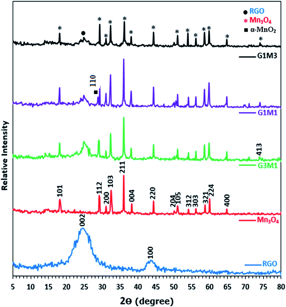
Fig. 1 presents the X-ray diffraction (XRD) patterns of reduced graphene (RG), bare Mn3O4 nanoparticles as well as the as-prepared RG–Mn3O4 nanocomposites. The diffraction peaks of RG seen at 2θ = 24.5° and 43.8° due to 002 and 100 reflections of graphitic carbon were depicted evidencing the reduction of graphene oxide to graphene during the hydrazine-thermal process. The calculated average interlayer distance was found to be 3.63 Å. Broadening of graphene peaks after reduction is diagnostic for lowering RG stacking defaults. On the other hand, the XRD pattern of Mn3O4 shows plenty of sharp peaks matched well with JCPDS no. 24-0734, indicating the formation of tetragonal Hausmannite-type Mn3O4 with space group I41/amd. No peaks of any other phases or impurities are observed demonstrating that the adopted method is suitable for the preparation of pure Mn3O4 phase. The latter phase elaborates diffraction peaks correspond to 101, 112, 200, 103, 211, 004, 220, 204, 105, 312, 303, 321, 224 and 400 planes. According to Scherrer analysis, the size of Mn3O4 is estimated to be ∼15 nm. The nanocomposites RG–Mn3O4 patterns indicate the coexistence of both RG diffraction lines; especially the 002 line, as well as those of the Mn3O4 phase. Vanishing of the 100 peak related to RG in all nanocomposites is indicative to the activity of the in-plane crystallite site. Increasing the Mn3O4 ratio relative to RG indicated more disordered graphene sheets as noticed via deterioration and splitting of the 002 peak, evidenced in G1M1 and G1M3 samples. The XRD patterns of G3M1 and G1M1 exhibited an increase in the Hausmannite Mn3O4 crystallinity. Where in G1M3, a significant decrease rather than increase in the phase forming Mn3O4 was depicted. A new peak at 2θ = 28.7° corresponding to the 110 plane is appeared in G1M1 and indexed to the α-MnO2 phase.29 Another peak at 2θ = 75° is seen in G1M1 and G1M3 samples ascribed to the 413 plane of Mn3O4; never depicted in their bare forms. Accordingly, the lines intensification observed in G1M1 and G3M1 compared to the bare Mn3O4 might give a hint about presence of other Mn species at similar positions of Mn3O4. The crystallite size of G1M3, G1M1 and G3M1 were respectively 12, 65 and 23 nm based of the calculation made on using the Debye–Scherer formula of the 211 plane.
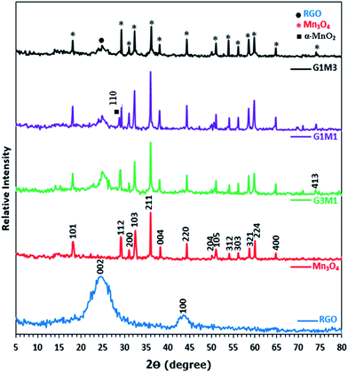 |
| | Fig. 1 XRD patterns of RGO, Mn3O4, G3M1, G1M1 and G1M3. | |
The surface morphology of the bare Mn3O4 and the nanocomposites G1M1 and G3M1 was investigated using HR-TEM and SAED analyses (Fig. 2). The image formation of the bare Mn3O4 shows spherical-like particles with an average size of 12 nm (Fig. 2A). The selected-area electron-diffraction pattern (SAED) of the nanoparticles is in harmony with the Hausmannite Mn3O4 phase and exposes strong ring patterns due to (101), (103), (211) and (220) planes. The spherical like particles were well distributed with a little tendency of forming clusters probably due to increasing the surface free energy of the nanoparticles. The TEM image shown in Fig. 2B for G1M1 reveals the existence of two types of morphological crystals for Mn3O4 including square and spherical architectures decorating graphene nanosheets. The square shape indicates an average dimension of 44 nm where the spherical ones reveal a dimension equal 10 nm. The inset figure confirmed the formation of the Hausmannite Mn3O4 phase via the selected area electron diffraction (SAED) pattern and thus exposed visible rings ascribed to 101, 103 and 211 lines. Another diffraction spot in the latter SAED pattern is also recognized and correlated to the 002 facet of graphene, giving a hint about the intimate contact between Mn3O4 and graphene nanosheets. The TEM image of the G3M1 sample (Fig. 2C) shows polyhedral structures including spherical, regular tetrahedron and rectangular, as illustrated in the high resolution TEM image shown as inset in Fig. 2C. They have an average diameter in the 10–12 nm range. The selected area electron diffraction pattern indicates visible rings that expose lattice fringes 101, 103, 211, 220 and 002 extended from exterior to interior and indexed respectively to Hausmannite Mn3O4 phase and graphene (002). This pattern indicates the well dispersion of Mn3O4 nanoarchitectures and its overlaying on graphene and rather emphasizes the strong interaction between them. That high dispersion of Mn3O4 within the great percentage of graphene sheets (G3M1) induces strong interaction between them and thus governs the particles size enlargement. A criterion about that interaction and consequences thereof concerning the agglomeration prevention of Mn3O4 nanoparticles as a result of its distribution between graphene nanosheets, is indeed comes through varying the morphology of the parent Mn3O4 and when it interacts with graphenes. That particle growth inhibition preserves the high-surface-area interface between Mn3O4 and graphenes. The images of G3M1 (Fig. 2D) indicated SAED pattern typical to all nanocomposites and rather shows spherical and square nanoarchitectures of dimension 12 nm and 50 nm, respectively.
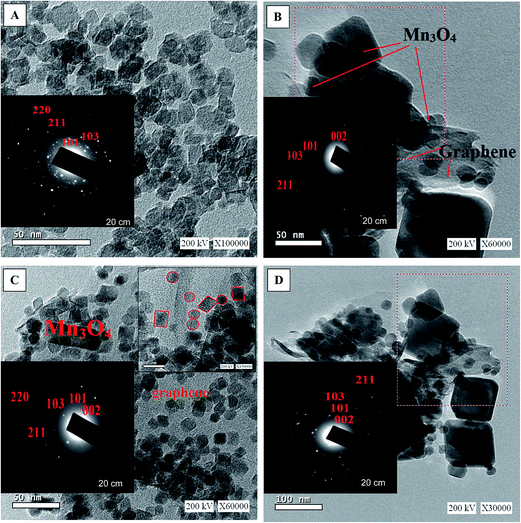 |
| | Fig. 2 TEM images of (A) Mn3O4 (B) G1M1 (C) G3M1 and (D) G1M3 together with the corresponding magnified HRTEM images and SAED patterns, as insets. | |
3.2. FTIR and UV-Vis spectroscopy
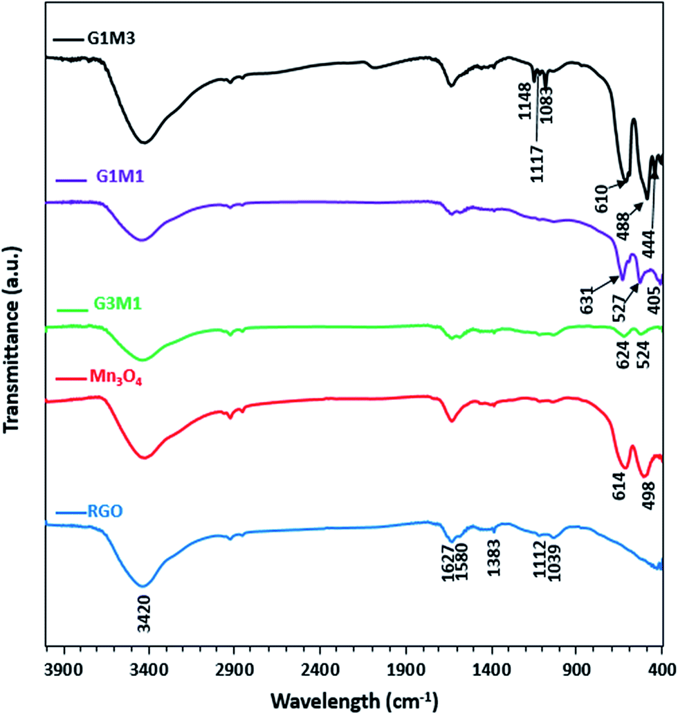
The FTIR spectra of the synthesized samples are presented in Fig. 3. Apparently RG spectrum indicates small bands at 1710, 1632, 1581, 1415, 1383, 1112 and 1039 cm−1 confirming the presence of residual oxide moieties on its surface. The bands at 1710 and 1632 cm−1 are respectively, assigned to vibrations of C![[double bond, length as m-dash]](https://www.rsc.org/images/entities/char_e001.gif) O stretching30 and absorbed water molecules.31 Whereas, the bands at 1415, 1383, 1112 and 1039 cm−1 are assigned to O–H deformation vibrations of tertiary C–OH,32 bending absorption of carboxyl group,33 C–OH stretching34 and C–O stretching vibration of the epoxy groups,35 respectively. The band at 1580 cm−1 is indicative to the GO reduction since it's correlated to the aromatic CC skeletal vibrations of unoxidized graphitic carbon.33–35 On the other hand, the Mn3O4 spectrum indicates prominent small bands at 1632, 1495, 1383, 1112 and 1039 cm−1 beside bands at 614 and 498 cm−1. The former bands assigned respectively, to adsorbed water molecules (1632 cm−1), OH deformation vibrations (1495 cm−1) and C–OH vibrations (1383–1039 cm−1). These bands are indicative of the prominent existence of some residual acetate moieties attached to the Mn precursor. The band at 614 cm−1 characteristics of the Mn–O bending mode at tetrahedral sites together with the band at 498 cm−1 correlated to the distortion vibrations of Mn–O in an octahedral position was observed. The G3M1 spectrum exhibits a combination of the bands existed for RG and Mn3O4 with revealing a reduction in intensity of the latter when compared with the bare Mn3O4. This gives a hint about the strong interaction between the moieties forming the G3M1 sample. Furthermore, shifting the Mn–O vibrations in the latter into longer wavenumbers (624 and 524 cm−1) compared to the bare Mn3O4 (613, 490 cm−1) reflects considerably the strong interaction exhibited between GO and Mn3O4. It is shown that the band area ratio of tetrahedral/octahedral in G3M1 is higher than that in the bare, which showed the reverse behaviour. In case of G1M1, the bands are somehow typical to those seen on G3M1 with slight shifting the low IR bands seen at 624 and 524 cm−1; in G3M1, into 631 and 527 cm−1, respectively. A new tiny band at 405 cm−1 is developed. This latter band is more close to Mn–O vibrations of MnO6 shown in α-MnO2 species,36 confirming the previously observed XRD results of G1M1. Interestingly, the G1M1 sample presented equal intensity ratio for tetrahedral and octahedral band structure. It appears also that the band at 1627 cm−1 undergoes splitting in G1M1 and G3M1 samples to give doublet and thus exposes in addition a band at 1580 cm−1. This gives a hint about the reduction of GO at such Mn3O4 loadings. However, increasing the ratio of Mn3O4 to GO (as in G1M3) has substantiated the intensities of the Mn–O bands, those exhibited at 610 and 488 cm−1 together with evolution of small bands at 444 and 400 cm−1 due to Mn3+ in octahedral sites.37,38 This highlights that increasing the concentration of Mn3O4 species (G1M3) indicates not only different geometrical structural of Mn3O4 but also specifies lower strength compared to other nanocomposites. Exposing the tetrahedral structure in G3M1 exceeding that of the thermodynamically favourable octahedral one may substantiate the high cationic mobility of Mn3O4, its superior electronic properties and its decreased particles sizes. In G1M3, the bands in the C–OH region have been substantiated (1050–1400 cm−1) together with OH stretching band at 3420 cm−1 with disappearing that at 1580 cm−1. This reflects the oxidation effect of Mn3O4 on RGO at such high loadings of Mn3O4 (G1M3). Existence of bands correlated to MnO2 in G1M1 and Mn2O3 in G1M3 might reflect the thermodynamic differences in surface energies that under wet conditions was amenable to expose MnO2 and Mn2O3 moieties together with the most prominent Mn3O4 mostly obtained under dry conditions.39,40 This has been ascertained via increasing the broadness of the OH stretching band as well as C–OH ones in G1M3. The absence of the more oxidized Mn2O3 species in the XRD pattern of G1M1 comprehends its small amounts and indeed raises the sensitivity of the FTIR technique. However, exceeding the XRD crystallinity of Mn3O4 peaks in G1M1 relative to pure Mn3O4 lines might indicate overlaying of other phase(s).
O stretching30 and absorbed water molecules.31 Whereas, the bands at 1415, 1383, 1112 and 1039 cm−1 are assigned to O–H deformation vibrations of tertiary C–OH,32 bending absorption of carboxyl group,33 C–OH stretching34 and C–O stretching vibration of the epoxy groups,35 respectively. The band at 1580 cm−1 is indicative to the GO reduction since it's correlated to the aromatic CC skeletal vibrations of unoxidized graphitic carbon.33–35 On the other hand, the Mn3O4 spectrum indicates prominent small bands at 1632, 1495, 1383, 1112 and 1039 cm−1 beside bands at 614 and 498 cm−1. The former bands assigned respectively, to adsorbed water molecules (1632 cm−1), OH deformation vibrations (1495 cm−1) and C–OH vibrations (1383–1039 cm−1). These bands are indicative of the prominent existence of some residual acetate moieties attached to the Mn precursor. The band at 614 cm−1 characteristics of the Mn–O bending mode at tetrahedral sites together with the band at 498 cm−1 correlated to the distortion vibrations of Mn–O in an octahedral position was observed. The G3M1 spectrum exhibits a combination of the bands existed for RG and Mn3O4 with revealing a reduction in intensity of the latter when compared with the bare Mn3O4. This gives a hint about the strong interaction between the moieties forming the G3M1 sample. Furthermore, shifting the Mn–O vibrations in the latter into longer wavenumbers (624 and 524 cm−1) compared to the bare Mn3O4 (613, 490 cm−1) reflects considerably the strong interaction exhibited between GO and Mn3O4. It is shown that the band area ratio of tetrahedral/octahedral in G3M1 is higher than that in the bare, which showed the reverse behaviour. In case of G1M1, the bands are somehow typical to those seen on G3M1 with slight shifting the low IR bands seen at 624 and 524 cm−1; in G3M1, into 631 and 527 cm−1, respectively. A new tiny band at 405 cm−1 is developed. This latter band is more close to Mn–O vibrations of MnO6 shown in α-MnO2 species,36 confirming the previously observed XRD results of G1M1. Interestingly, the G1M1 sample presented equal intensity ratio for tetrahedral and octahedral band structure. It appears also that the band at 1627 cm−1 undergoes splitting in G1M1 and G3M1 samples to give doublet and thus exposes in addition a band at 1580 cm−1. This gives a hint about the reduction of GO at such Mn3O4 loadings. However, increasing the ratio of Mn3O4 to GO (as in G1M3) has substantiated the intensities of the Mn–O bands, those exhibited at 610 and 488 cm−1 together with evolution of small bands at 444 and 400 cm−1 due to Mn3+ in octahedral sites.37,38 This highlights that increasing the concentration of Mn3O4 species (G1M3) indicates not only different geometrical structural of Mn3O4 but also specifies lower strength compared to other nanocomposites. Exposing the tetrahedral structure in G3M1 exceeding that of the thermodynamically favourable octahedral one may substantiate the high cationic mobility of Mn3O4, its superior electronic properties and its decreased particles sizes. In G1M3, the bands in the C–OH region have been substantiated (1050–1400 cm−1) together with OH stretching band at 3420 cm−1 with disappearing that at 1580 cm−1. This reflects the oxidation effect of Mn3O4 on RGO at such high loadings of Mn3O4 (G1M3). Existence of bands correlated to MnO2 in G1M1 and Mn2O3 in G1M3 might reflect the thermodynamic differences in surface energies that under wet conditions was amenable to expose MnO2 and Mn2O3 moieties together with the most prominent Mn3O4 mostly obtained under dry conditions.39,40 This has been ascertained via increasing the broadness of the OH stretching band as well as C–OH ones in G1M3. The absence of the more oxidized Mn2O3 species in the XRD pattern of G1M1 comprehends its small amounts and indeed raises the sensitivity of the FTIR technique. However, exceeding the XRD crystallinity of Mn3O4 peaks in G1M1 relative to pure Mn3O4 lines might indicate overlaying of other phase(s).
 |
| | Fig. 3 FTIR spectra of RGO, Mn3O4, G3M1, G1M1 and G1M3. | |
The UV-Vis absorption spectra of pure Mn3O4 and GM hybrids are compared in Fig. 4. The Mn3O4 spectrum shows a strong band at 210 nm due to the allowed O2− → Mn2+ and/or O2− → Mn3+ charge transfer transitions with almost no absorption in the visible light region. In comparison with the latter sample, the nanocomposite samples show strong absorption in the visible light region. The nanocomposites exhibit a band at 230 nm; besides the mentioned one at 210 nm, due to π–π* transitions of the aromatic CC bonds in graphene structure. The nanocomposites containing graphene that showed absorption enhancement in the whole region were in the order; G3M1 > G1M1 > G1M3. This indeed maximized the effect of graphene appropriate percentages relative to Mn3O4 along with the color changes from black to grey. This was in concordance with the reported results of other GR-including nanocomposites.41 The electronic absorption spectra of the nanocomposites also show broad bands from 390 to 530 nm in G1M3 where it extends into 600 nm in G1M1 and G3M1. This indeed is correlated to d–d crystal field transitions on octahedral Mn3+ species42 and rather proposes the strong interaction between the moieties forming the composite. This is expected to increase the harvesting capability of the nanocomposites to have a great impact on their photocatalytic performances probably in the same sequence under visible illumination. The band gap energy of the samples is calculated via using the equation:
where
ν,
α,
Eg and
A is respectively light frequency, absorption coefficient, band-gap energy and a constant.
43 The part
n is a constant fits with 1/2 to comprehend that the optical transition is of a direct allowed type.
44 Accordingly, the estimated band-gap energies of G, Mn
3O
4, G1M1, G3M1 and G1M3 based on the latter equation are 1.39 eV, 3.1 eV, 1.44 eV, 1.41 eV and 2.05 eV, respectively (
Fig. 4 inset). All the GM nanocomposite samples have band gap energies in the region between those of graphene and Mn
3O
4 accomplishing the strong interaction devoted between them.
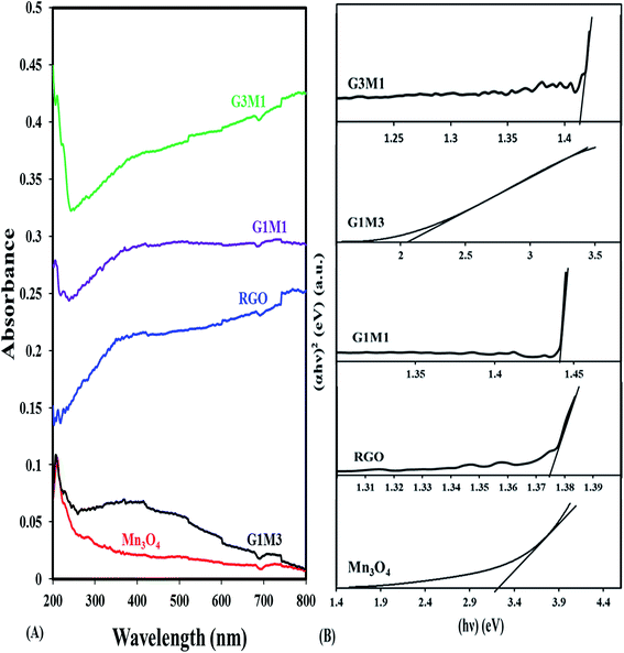 |
| | Fig. 4 UV-Vis absorption spectra of RGO, Mn3O4, G3M1, G1M1 and G1M3, and their corresponding plots of (αhν)2versus (hν) for energy bandgap (Eg) determination. | |
3.3. Raman spectroscopy
To gain more information about the structure of the graphene sheets and its interaction with Mn3O4, Raman spectra were recorded (Fig. 5). The Raman spectrum of the bare Mn3O4 shows a strong peak at 641 cm−1 ascribed to the A1g mode correlated to the oxygen vibrations in the MnO6 unit.45 The Raman spectrum of G1M1 displays the G peak at 1570 cm−1 correlated to the ordered sp2 bonded carbon together with the D peak at 1347 cm−1 due to edges or disordered layers.46 The small peaks in the margin 200–400 cm−1 ascribed to Mn3O4 modes47 were intensified in the G1M1 spectrum compared to the pristine Mn3O4 to comprehend the proposed weak interaction between the moieties forming G1M1. Conversely, the G3M1 spectrum illustrates in addition to D and G peaks a very small peak due to the free Mn3O4 (641 cm−1) that constitutes 1/5 of its intensity in G1M1 and 1/4 to that in the bare Mn3O4. Taking into consideration the Mn to G ratios, one easily confirms that the interaction between Mn3O4 with graphene was more intense in G3M1 compared to the other nanocomposites. Shifting the G band from 1570 cm−1 in G1M1 and G1M3 to 1580 cm−1 in G3M1 confirms the devoted strong interaction of Mn3O4 with graphene and rather announces lowering of graphene layer thickness in the latter sample than those in the former.47,48 Both of the nanocomposites show the 2D band; characteristics of two phonon lattice vibration process,48 of the same shape and position extending from 2550 to 2850 cm−1. Accordingly, the synthesized graphene is multilayered given that D in RG is very strong than the 2D. The intensity ratio of D and G peaks (ID/IG) offers a precise measure of the disorder and crystallite size of the graphitic layers. The ID/IG intensity ratio of RG (1.34) exceeded those of G3M1 (1.31), G1M1 (1.26) and G1M3 (1.12) confirming a relative lower density of imperfection in RG following the Mn3O4 incorporation.
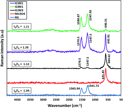 |
| | Fig. 5 Raman spectra of Mn3O4, G3M1, G1M1 and G1M3. | |
3.4. Surface texturing
Fig. S1† presented the N2 adsorption–desorption isotherms of some synthesized samples in conjunction with their pore size distribution (PSD) curves. They demonstrate type II isotherm with H3 hysteresis loops characterizing aggregates of plate-like or slit-shaped pores.49 Incorporation of Mn3O4 into RG decreases the SBET value from 142.6 m2 g−1; in pristine RG, into 116 m2 g−1 in G1M1 and 105.6 m2 g−1 in G3M1. The hysteresis loops of the samples close at P/Po values of 0.46, 0.46 and 0.45 for RG, G1M1 and G3M1, respectively. This signifies the presence of alike large pores in all the samples except RG that shows another hysteresis closes at P/Po = 0.84, representing the involvement of micropores as well. That hysteresis is disappeared following Mn3O4 involvement illustrating the well incorporation of the latter between RG sheets. As a confirmation for the mentioned order in surface area, the pore volume values indicate alike trend via giving values equal 0.1124, 0.0912 and 0.0818 cm3 g−1 for RG, G1M1 and G3M1, respectively. This elaborates that the pore volumes are reduced where the pore radii are only narrowed for the G1M1 sample (27.67 Å) and it was reluctant in G3M1 (28.9 Å). The pore size distribution (PSD) curves of all the samples have shown the existence of trimodal type of pores (2 nm, 2.9 nm and 4.2 nm) all occur in the low margin of mesopores. The relative intensity of the peaks; correspond to different types of the pores, suffered a decrease in the order; G3M1 > G1M1 > RG. This elaborates the well inclusion of Mn3O4 between RGO sheets in G3M1 and G1M1 samples accomplishing the strong interaction between the moieties forming these samples. Decreasing the pore volume of the G3M1 sample compared to rest of samples while keeping its pore radius unaffected reflects the dispersion of Mn3O4 deep between RG sheets.
3.5. Photocatalytic degradation of the MB dye
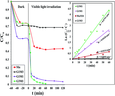
The photocatalytic degradation of as-synthesized nanocomposites RG–Mn3O4 (G3M1, G1M1 and G1M3) was studied via using the methylene blue (MB) dye at a concentration of 20 ppm and at room temperature. These samples were initially left for 60 min in MB solutions before irradiation for ascertaining equilibrium adsorption. Upon visible light irradiation (88 W, λ > 420 nm), the G1M3 sample did not exhibit any activity apart from that related to the dye absorption and comprised of 30% (Fig. 6). The photocatalyst G1M1 exhibits MB degradation equal 92%, showing fast oxidative decomposition upon increasing the RG ratio. It seems also that the RG ratio affected the adsorption process to reach 52% in this latter sample. A further increase in the RG ratio as in the G3M1 sample has indicated an efficient MB degradation via achieving 100% in only 60 min. Although the latter catalyst contains the highest RG ratio, it indicates low absorption percentages under dark condition comprised of 24%. It is necessarily declaring that this reaction proceeds without any oxidizing agent unlike those devoted by Chunxiang He et al.9 and Shaobin Wang et al.14 whom used H2O2 and peroxymonosulfate, respectively with the composites of Mn3O4/GO. This reveals an increase of our samples oxidizability under photo-irradiation. On the other hand, the bare Mn3O4 indicates dark adsorption comprised of 30% that continues to give 58% degradation under visible light irradiation after 120 min. Accordingly, it seems that the synergy between Mn3O4 and RG plays a significant role in the dye degradation via photocatalysis. Concisely, the RG/Mn3O4 ratio and specifically G3M1 manipulates the efficient decomposition of the MB dye since the individual components showed lower catalytic activity than the nanocomposites. Plotting lnCo/C vs. time (min) indicates straight lines (see the inset in Fig. 6) with slopes indicative to the reaction rate constants. These lines indicate that the oxidation reaction follows pseudo-first order rate kinetics. The rate constant values that performed at 298 K were in the order: G3M1 (0.0791 min−1) > G1M1 (0.0428 min−1) > Mn3O4 (0.0114 min−1) > G1M3 (0.0005 min−1). Since, the nanocomposite G3M1 presented the most promising photo-activity result, it has been used for performing further reactions. At certain reaction intervals, the UV-Vis absorption spectra of the MB dye were undertaken while tracing its photocatalytic degradation using the nanocomposite G3M1. As shown in Fig. S2,† two absorption peaks at 615 and 664 nm are observed characterizing the MB typical peaks.50 These absorption peaks diminish with time and the solution turns colourless gradually within 60 min irradiation time. The TOC% of the same sample taken during the 60 min reaction time; inset in Fig. S2,† indicates 60% elemental carbon representing the photodegradation ratio of the dye organic carbons. However, the difference between C/Co and TOC% values; typical of 40%, are mostly correlated to the presence of non-degradable intermediates produced during the photo-degradation process. However, extending the time into 120 min has accomplished the 100% TOC degradation verifying the complete transformation of organic carbons into elemental carbons.
 |
| | Fig. 6 Photocatalytic degradation of the MB dye by Mn3O4, G3M1, G1M1 and G1M3 photocatalysts under visible light irradiation: reaction conditions: (lamp power = 88 W, filter λ = 420 nm, catalyst weight 100 mg, dye conc. 20 ppm). Insets are the kinetic fits for MB degradation via the as-synthesized photocatalysts. | |
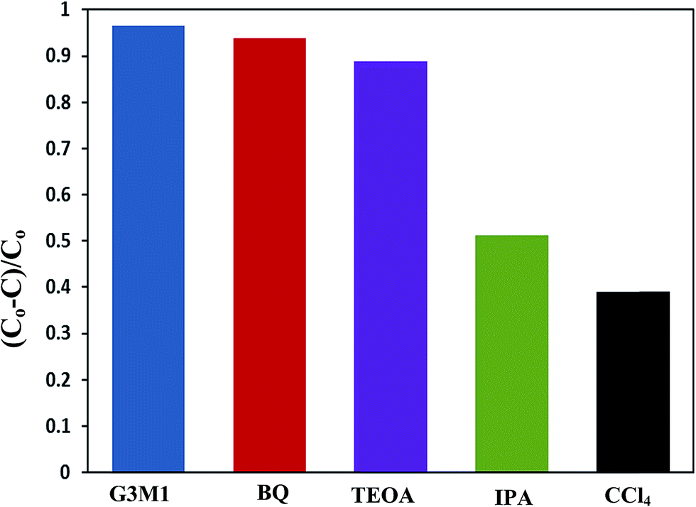
To shed an idea about the reactive species could be involved in the oxidation process, some recognized scavengers were added to investigate their role on the reaction rate. Accordingly, the effects of the addition of benzoquinone; BQ, isopropanol; IPA, triethanolamine; TEOA, and carbon tetrachloride; CCl4, on the catalytic oxidation of the MB dye over the photocatalyst G3M1 have been investigated under identical experimental conditions (Fig. 7). It has been shown that the reaction rate was relatively retained upon using BQ reflecting the small effect of the ˙O2− species. The experiment with IPA has indicated a higher decrease than that evoked via BQ, proposing the influential effect of ˙OH. A significant decrease was obtained for the MB oxidation following the addition of TEOA and CCl4 comprehending the efficacy of both holes and electrons in the MB oxidation mechanism. This suggests that the intimate contact between Mn3O4 and graphene in G3M1; as confirmed from HRTEM-SAED, Raman and FTIR, is beneficial for the production of the main reactive species ˙OH resulted due to the visible light absorption. Indeed, the produced photogenerated holes from the VB of Mn3O4 were responsible for creating the latter reactive species as a consequent of its interaction with OH−/H2O species. Hypothetically, based on conduction and valence band edge energy calculation,51 the photoexcited electrons in the CB of Mn3O4 in G3M1 can reduce O2 to ˙O2− since the CB edge potential (of −4.01 eV vs. NHE) is more negative compared to the standard redox potentials of EΘ (O2/˙O2−) (−0.33 eV vs. NHE). However, the scavenger study indicates the negligible effect of the latter reactive species. Compatibly, ˙OH can be created by ˙O2− rather than h+ in the VB of Mn3O4 because of the more negative Mn3O4 VB potential (−0.2.6 eV) relative to the standard redox potential of OH−/˙OH (EΘ = 2.4 eV).49,52 Hence, the generation of ˙OH and the involvement of ˙O2− in the synthesis of the latter can be proposed via the following equations.
| | | ˙O2− + ECB− + 2H+ → H2O2 and/or ˙O2− + H+ → HOO˙ → ˙OH + O and H2O + photon → ˙OH + ˙H | (3) |
| | | ˙O2− + H2O2 → ˙OH + OH− + O2 | (4) |
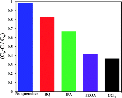 |
| | Fig. 7 Effect of reactive scavengers on the degradation activity of the G3M1 photocatalyst towards MB under visible light irradiation and under the mentioned reaction conditions. | |
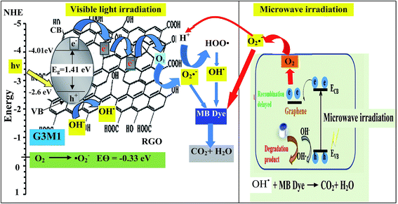
Based on the presented results, the photocatalytic mechanism can be proposed as follows (Scheme 1). In the Mn3O4/RG composites, Mn3O4 attached on the surface of RG produces electron–hole pairs as a result of photons absorption when exposed to visible light irradiation. Effective separation of the charges is attained given that RG acts as an effective scavenger for the produced electrons. Herein, electrons absorbed by RG can react with the adsorbed O2 to yield ˙O2− that by its turn transferred into ˙OH together with the OH− ions dedicated as well to produce ˙OH. Also, ˙OH can be obtained via direct water oxidation or reduction of H2O2. Investigation that the latter moieties is in situ formed is traced by measuring the light absorption of the titanic-hydrogen peroxide compound.52 Accordingly, ˙OH moieties compile their definite effects in effective MB dye oxidization. Nevertheless, one must bear in mind that our RG is functionalized by residual oxygen moieties on its surface; in conformity with Eg data ascertaining its semiconducting property, enabling it to take part in the photoreaction products. Accordingly, the photo-generated holes could be capture by not only the lattice oxygen in Mn3O4 but also those on RG sheets to form ˙OH active species. On the other hand, the photogenerated h+ in the VB is also amenable for generating ˙OH via the reaction with H2O.
 |
| | Scheme 1 | |
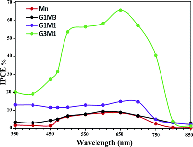
In addition, it is very important to confirm that the photodegradation obtained for the nanocomposites is consistent with the values estimated from incident photon to current efficiency (IPCE) spectra (Fig. 8). This is because photodegradation is entirely dependent on the incident light and the consequences thereof concerning the impinged photons. As shown in Fig. 8, the G3M1 electrode possessed the highest IPCE values over the wide range from 350 to 750 nm compared to rest of the samples. This result was in harmony with the devoted UV-Vis absorption spectra (Fig. 4) in which G3M1 has indicated the highest absorption throughout all the studied range (200–800 nm) and rather it indicates the lowest Eg value (1.41 eV). Increasing IPCE of the G3M1 electrode in the wavelength range of 600–700 nm could also be due to increasing the absorption capacity of the MB dye (Fig. 8). Increasing the IPCE of same sample in the narrow wavelength range of 470–490 nm; in which the MB dye has a low absorption for incident light, reflects that this promotion is directly correlated to the phenomenon of light scattering. This result further confirmed the superior light absorption and scattering properties of the G3M1 electrode in the long wavelength region. This explains the higher efficiency of G3M1 in photodegrading the MB dye compared to rest of the catalysts. Exposing the tetrahedral structure of Mn3O4 in G3M1 than the octahedral one; as deduced from FTIR results, may substantiate the facile mobility of Mn3O4 in enhancing the photocatalysis of this specific sample together with its decreased particles size.
 |
| | Fig. 8 Incident-photon-conversion efficiencies (IPCE%) of Mn3O4, G3M1, G1M1 and G1M3. | |
It's of important notifying that at the 25 wt% of RGO loading (as in G1M3), no photoactivity is exhibited where after increasing the weight ratio of RGO compared to Mn a superior photoactivity is attained. This is due to at the former ratio, an oxidized GO is obtained due to the excessive amounts of Mn3O4 (75 wt%) and this prohibits the facile electron transfer due to its scavenger throughout oxygen functional groups leading to high loss of charges. Conversely, increasing the ratio into 75% graphene (as in G3M1) reduces tremendously the residual oxygen, as reveled from IR results, and thus acts as an electron acceptor/donor capable of performing magnificent role in the dye degradation. Convincingly, the strong adhering of Mn3O4 into RG; which retained the particles size of the former at ∼12 nm, has shown exceptional optical and texturing properties those in turn caused high oxidative decomposition for the MB dye in the absence any oxidants unlike many comparable nanocomposites.9,14,25
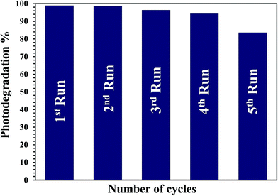
The stability and recyclability of the G3M1 nanocomposite was evaluated by successive tests for the MB decolorization (Fig. 9). It is established that the G3M1 photocatalyst can work at least four cycles without noticeable loss in the catalytic activity, demonstrating the long-term durability of this nanocomposite. Whereas, the fifth run indicates retaining of the 85% of the catalyst activity proposing an excellent stability while reusing for 300 min.
 |
| | Fig. 9 The recycle test during degradation of MB using G3M1 under visible light illumination. | |
3.6. Microwave absorption of Mn3O4/graphene for MB degradation
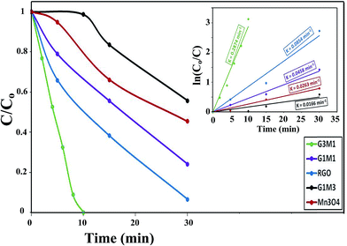
Fig. 10 shows the normalized degradation curves of MB treated in the microwave reactor; for 30 min at 373 K and under 1 atm pressure, with the nanocomposite catalysts as well as with the free Mn3O4 catalyst. During the microwave treatment, the nanocomposite G3M1 catalyst indicates the best MB degradation performance by signifying 100% color removal. This only takes 10 min compared to 60 min in the photocatalytic reaction performed for the same sample. Accordingly, the consequence of the studied nanocomposites was in the order; G3M1 > G > G1M1 > Mn > G1M3. These results maximized the role of the synergistic effects between Mn3O4 and graphene at high percentages of the latter (G3M1) since, it shows higher degradation percentages than pristine Mn3O4 and graphene nano-architectures. It was found that the G1M1 catalyst exhibits a microwave catalytic activity comprised of 70% degradation whereas that of G1M3 indicates 40%, both in 30 min irradiation time. The microwave degradation of MB by a direct microwave irradiation in the absence of a catalyst was almost zero. Additionally, to exclude that the degradation has nothing to do with the sample heating, the nanocomposites were heated to 373 K with the MB solution for 1 h away from microwave irradiations to comprehend zero degradation. Whereas, the microwave degradation of MB in presence of nanocomposites was found to follow pseudo-first-order decay kinetics.53 Based on the Langmuir–Hinshelwood model, the estimated reaction rate (Fig. 10 inset) was in the order G3M1 (0.287 min−1) > G (0.085 min−1) > G1M1 (0.045 min−1) > Mn (0.026 min−1) > G1M3 (0.016 min−1) (Fig. 11). It's interesting notifying that the activity of microwave irradiation of G3M1 while degrading MB exceeded that obtained via photocatalysis by 3.5 times.
 |
| | Fig. 10 Microwave degradation of MB dye by Mn3O4, RGO, G3M1, G1M1 and G1M3 nanocomposites: reaction conditions: (temp. = 373 K, catalyst weight 100 mg, dye conc. 20 ppm, 800 W, 2.45 GHz). Insets are the kinetic fits of MB degradation via the as-synthesized nanocomposites. | |
 |
| | Fig. 11 Effect of reactive scavengers on the degradation activity of the G3M1 nanocomposite towards MB under microwave irradiation and under the mentioned reaction conditions. | |
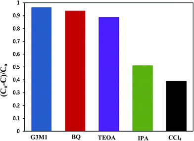
The scavenger studies for detecting the reactive species could be responsible for MB degradation while employing the microwave absorption property of nanocomposites were performed (Fig. 11). Notably, when TEOA and BQ used, the degradation efficiency is overall similar to that of the blank without scavengers and thus nullifies the influence of holes and ˙O2− species. Whereas, upon using IPA and CCl4 a significant decrease in activity is perceived relative to that of the blank implying that ˙OH and electrons are the major reactive species for G3M1. This advocates that the coupling effect between microwave and the active ˙OH species on Mn3O4 incorporated graphenes is participated in the MB degradation. It has been notified that ˙OH is produced considerably by h+ in the VB of Mn3O4/graphene (G3M1) owing to its more negative potential than the standard redox potential of OH/˙OH (EΘ = 2.4 eV).53 The violent motion of polar materials; exerted due to collisions between reactant molecules due to microwave irradiation, can compete with the catalytic reactive species to accelerate degradation of the MB dye.
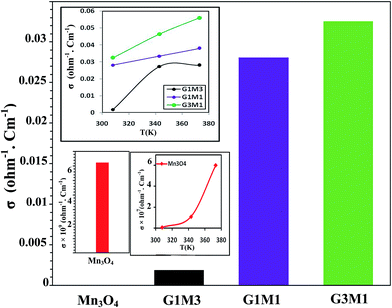
To configure the role of electrons during the microwave MB degradation performance; as committed from the trapping experiments, the electrical conductivity of as-synthesized nanocomposites as well as the bare Mn3O4 was measured at temperature range from room temperature to 373 K (Fig. 12). The electrical conductivity values were found to decrease from 0.033 Ω−1 cm−1, 0.028 Ω−1 cm−1, 0.002 Ω−1 cm−1 and 6.0 × 10⁻⁹ Ω−1 cm−1 for G3M1, G1M1, G1M3, and Mn3O4, respectively. This indicates that the combination of graphene with Mn3O4 nanocomposites can strongly increase the electronic conductivity compared to the bare Mn3O4. It also indicates the potentiality of graphene specifically in the nanocomposite G3M1, reflecting the synergism between the components forming this composite. Based on the high absorptivity of carbon containing materials including graphenes to microwave, hot-spots are formed to act as oxidation centres for the pollutants oxidation.53 That selective heating stimulates molecular rotation causing a decrease in the activation energy (see Fig. 10).
 |
| | Fig. 12 Conductivity results of Mn3O4, G3M1, G1M1 and G1M3 samples measured at room temperature and at 373 K. Inset is the σ vs. T for exploring the effect of increasing temperature on the conductivity. | |
Since microwave assists the rise of temperature of the samples thus, an increase in the number of carriers and lattice vibrations is expected to be obtained.52 Indeed, increasing the temperature increases the number of carriers and consequently it leads to conductivity elevation (inset in Fig. 12). Scheme 1 also illustrates the effect of ˙OH and electrons evoked while microwave irradiation on the MB degradation. Of particular interest, although the nanocomposites G1M1 and G1M3; of alike thickness, show the presence of small amounts of MnO2 and Mn2O3 species; as devoted from XRD and IR results, they still indicate lower conductivity values than G3M1. This declares that the geometric defects obtained in G1M1 and G1M3 samples such as dislocations and grain boundaries54 are great; as exactly devoted from surface properties and TEM results. Consequently, such grain boundaries in graphene can disrupt the electron transfer and thus being trapped causing the depletion in charge carriers. The strong interaction devoted between Mn3O4 and graphene in G3M1; confirmed via IR, Raman, TEM-SAED and surface texturing data, minimizes the presence of discrete boundaries, structural disorders and surface imperfections between the moieties forming this sample. On the other hand, the lattice vibrations create phonons and thus an expected interaction between electron–phonon can be perceived.54 Undoubtedly, G1M1 and G1M3 must have shown more charge carriers than G3M1 due to evoking Mn4+ and Mn3+ species on their surfaces; as depicted via XRD and IR results. However, the devoted decrease in their conductivities explains the possibility of hampering the electrons by phonons and as a result affecting the oscillation mode occurs in their lattice structures influencing their conductivities (Fig. 12).
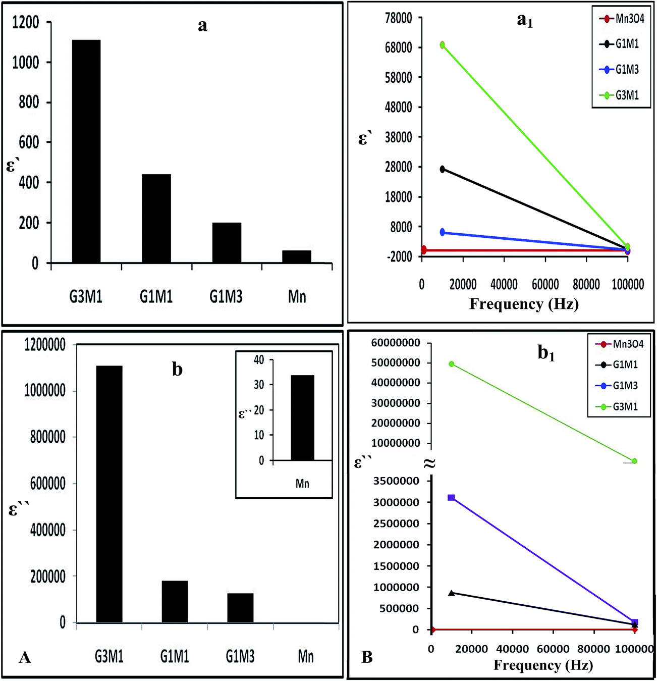
Increasing the microwave catalytic activity of G3M1 was due to enhancement of the microwave absorption as a result of the change occurring in dielectric constant and dielectric loss caused by the addition of Mn3O4 to graphene. Under the alternating electromagnetic field, interfacial and space-charge polarization can easily be formed at the interface of Mn3O4/graphene and also due to the conducting nature of graphene and the dielectric nature of Mn3O4. Fig. 13a shows that the nanocomposites dielectric constant (ε−); inferred to the storage ability of electric current, decrease continuously with increasing frequencies to be in the order; G3M1 > G1M1 > G1M3 > Mn. The monotonous decline in dielectric constants on increasing frequencies may be attributed to the combined contribution caused by electronic, ionic, and interfacial polarization.58 The observed dielectric distribution at low frequencies can be explained on the basis of the Maxwell–Wagner theory of interfacial polarization59 by which the dielectric structure of the composite consists of two layers. The number one layer stands for a large number of grains that act as conducting layer at lower frequencies and the other layer consists of grain boundaries that act as highly resistive medium at higher frequencies. At low frequencies, the polarization process in composites of high percentages of Mn3O4 (G1M3) can be described as a local displacement of electrons via hopping mechanism between Mn3+ and Mn4+ and an orientation of electric dipole in the direction of the applied field. Nevertheless, the monitored decrease in the latter sample dielectric constant is in part due to the presence of residual oxygenated functional groups; depicted via IR results. That presumably lessens the direct contact between graphene nanosheets and thus facilitates the electron transfer through oxygen functional groups leading to high dielectric loss (Fig. 13b). Increasing the microwave absorption property of G3M1 could also be caused by dielectric relaxation and interfacial scattering.55,56 The dielectric relaxation and polarization was mainly induced by interfacial multipoles, which took place along the boundaries between graphene sheets and Mn3O4 moieties.57,58 It has been documented that charges would transfer throughout the interface in a metal graphene heteroarchitecture due to their different work function and thus an electron transfer from Mn3O4 to graphene can be anticipated. Accordingly, a charge transfer process can rationally be assumed at the interface of G3M1, leading to the introduction of the free carriers into graphene sheets. The latter carriers would vibrate with the microwave motivation giving rise to electric polarization in graphene and thus increase the value of ε′ in G3M1 compared to rest of the composites (Fig. 13a). Furthermore, ε′ of all nanocomposites decreases with increasing frequency (Fig. 13a1) owing to the relaxation of polarization and thus shows a dielectric dispersion. The small-size particles (12 nm) observed in G3M1 involves large number of particles per unit volume resulting in an increase of the dipole moment per unit volume and thus induces the highest dielectric constant. In the meantime, the motion of the introduced free carriers would attenuate the microwave energy, resulting in the enhancement of the dielectric loss ε′′ (Fig. 13b). Attenuation of dielectric loss with increasing frequencies was also attained; as seen in the corresponding Fig. 13b1. Diminishing the dielectric constant with increasing frequency is dedicated to the polarization decrease of the dipoles when the electric field propagates with high frequencies. Interestingly, the G3M1 sample has indicated the lowest decrease in dielectric loss with increasing frequency between all samples. This latter behaviour is explained on the basis that in dielectric nanostructured materials, interfaces are produced with large volume fractions involving great number of defects such as vacancies, dangling bonds and microporosities.58 These can cause a change in negative and positive space charge distribution at the interfaces. Such space charges when subjected to an electric field, they trapped by defects to form lots of dipole moments. On the other hand, these dipole moments at low frequencies follow the change of the electric field59 and thus both the dielectric loss and the dielectric constant display high values.
 |
| | Fig. 13 The dielectric constant (a) and dielectric loss (b) of Mn3O4, G3M1, G1M1 and G1M3 and their counterparts (a1) and (b1) as a function of frequency change in the margin from 1.0 Hz to 100 kHz. | |
The dielectric properties of the composites are usually correlated to the surface morphology of reduced graphene nanosheets, since it increases as the graphene ratio increase (Fig. 13a and b). Accordingly, the random distribution of the conserved sp2 and distorted sp3 carbons decorated by various oxygen containing functional groups can be anticipated.60 Such distribution in RGO works as a nanocapacitor electrode separated by the Mn3O4 dielectric material. Thus, the revealed considerable improvement in dielectric constant can be attributed to the formation of huge number of nanocapacitors inside the composite.61 This is believed to originate due to the presence of residual oxygenated functional groups that apparently lessen the direct contact between graphene nanosheets.62 Consequently, the large capacitance caused by each nanocapacitor results in a noticeably high local electric field. An environment is afterwards created which is conducive for migration and accumulation of charge carriers at the RGO/Mn3O4 interface. That interfacial polarization named Maxwell–Wagnar effect is considered to be responsible for the large dielectric constant at low frequency region.63 Conversely, the escape current is principally responsible for the high dielectric loss in nanocomposites, as validated in G1M1 and G1M3. This explains that oxygenated functional groups on RGO are not as an insulating layer or intrinsic barriers that limits the current leakage64 but facilitates the electron transfer through oxygen functional group leading to high dielectric loss.
4. Conclusions
The polyhedral nanoarchitecture graphene/Mn3O4 formed at the ratio of G3M1 has shown fascinating photocatalytic performances; under visible light illumination without any oxidants, and microwave irradiation for the purpose of the MB degradation. The experimental results of this type of smart material evokes some important factors by which the enhancement was revealed such as (i) high optical properties explained via exceeding the visible light absorption of the sample in the 400–800 nm region as well as increasing the IPCE% value (ii) the devoted strong interaction between the moieties forming G3M1 and the consequence thereof concerning the decrease in Eg as well as the delay in the charges recombination (iii) increasing the conductivity of this sample at room temperature (i.e. indicative to photocatalysis) and rather its enhancement at 373 K (i.e. indicative to microwave irradiation) (iv) the superior increase in the dielectric constant at the low frequency margin, at which microwave absorption takes place, explained the extraordinary photocatalytic MB degradation. The excellent microwave absorption seen in G3M1 was attributed to the charge transfer at the latter nanocomposite interface as well as the interfacial polarization that well explained in view of the Maxwell–Wagnar effect.
References
- M. M. Mohamed, B. H. M. Asghar and H. A. Muathen, Catal. Commun., 2012, 28, 58 CrossRef CAS.
-
(a) M. M. Mohamed, Microporous Mesoporous Mater., 2008, 109, 445 CrossRef CAS;
(b) M.-Q. Yang, N. Zhang, M. Pagliaro and Y.-J. Xu, Chem. Soc. Rev., 2014, 43, 8240 RSC.
- M. M. Mohamed, I. Othman and R. M. Mohamed, J. Photochem. Photobiol., A, 2007, 191, 153 CrossRef CAS.
- J. Bogdan, A. Jackowska-Tracz, J. Zarzyńska and J. Pławińska-Czarnak, Nanoscale Res. Lett., 2015, 10, 57 CrossRef.
- D. F. Ollis, Environ. Sci. Technol., 1985, 19, 480 CrossRef CAS.
- F. Pan, J. Jin, X. Fu, Q. Liu and J. Zhang, ACS Appl. Mater. Interfaces, 2013, 5, 11108 CrossRef CAS.
- P. V. Kamat, J. Phys. Chem. Lett., 2011, 2, 242 CrossRef CAS.
-
(a) M. Kang, E. D. Park, J. M. Kim and J. E. Yie, Appl. Catal., A, 2007, 327, 261 CrossRef CAS;
(b) N. Zhang, M.-Q. Yang, S. Liu, Y. Sun and Y.-J. Xu, Chem. Rev., 2015, 115(18), 10307 CrossRef CAS.
- Y. Li, J. Qu, F. Gao, S. Lv, L. Shi, C. He and J. Sun, Appl. Catal., B, 2015, 162, 268 CrossRef CAS.
- M. Seredych and T. J. Bandosz, J. Mater. Chem., 2012, 22, 23525 RSC.
- J. Y. Zhu and J. H. He, ACS Appl. Mater. Interfaces, 2012, 4, 1770 CrossRef CAS.
- S. Bag, K. Roy, C. S. Gopinath and C. R. Raj, ACS Appl. Mater. Interfaces, 2014, 6, 2692 CrossRef CAS.
- J. W. Lee, A. S. Hall, J. D. Kim and T. E. Mallouk, Chem. Mater., 2012, 24, 1158 CrossRef CAS.
- Y. Yao, C. Xu, S. Yu, D. Zhang and S. Wang, Ind. Eng. Chem. Res., 2013, 52, 3637 CrossRef CAS.
- N. Birkner and A. Navrotsky, Am. Mineral., 2012, 97, 1291 CrossRef CAS.
-
(a) Z. H. Wang, D. Y. Geng, Y. J. Zhang and Z. D. Zhang, J. Cryst. Growth, 2008, 310, 4148 CrossRef CAS;
(b) N. Zhanga and Y.-J. Xu, CrystEngComm, 2016, 18, 24 RSC.
- S. Yuan, Y. Fan, Y. Zhang, M. Tong and P. Liao, Environ. Sci. Technol., 2011, 45, 8514 CrossRef CAS.
- X. Quan, X. Liu, L. Bo, S. Chen, Y. Zhao and X. Cui, Water Res., 2004, 38, 4484 CrossRef CAS.
- J. E. Atwater and R. R. Wheeler Jr, Appl. Phys. A, 2004, 79, 125 CrossRef CAS.
- Y. Wu, P. Qiao, J. Qiu, T. Chong and T. S. Low, Nano Lett., 2002, 2, 161 CrossRef CAS.
- H. Lin, H. Zhu, H. Guo and L. Yu, Mater. Lett., 2007, 61, 3547 CrossRef CAS.
- L. Olmedo, P. Hourquebie and F. Jousse, Adv. Mater., 1993, 5, 373 CrossRef CAS.
- V. Petrov and V. Gagulin, Inorg. Mater., 2001, 37, 93 CrossRef CAS.
- S. Sun, H. Zeng, D. B. Robinson, S. Raoux, P. M. Rice, S. X. Wang and G. Li, J. Am. Chem. Soc., 2004, 126, 273 CrossRef CAS.
- X. Fang, J. Xiao, S. Yang, H. He and C. Sun, Appl. Catal., B, 2015, 162, 544 CrossRef CAS.
- X. Wang, L. Mei, X. Xing, L. Liao, G. Lva, Z. Li and L. Wu, Appl. Catal., B, 2014, 160–161, 211 CrossRef CAS.
- C. C. Hu, Y. T. Wu and K. H. Chang, Chem. Mater., 2008, 20, 2890 CrossRef CAS.
- T. C. Liu, W. G. Pell and B. E. Conway, Electrochim. Acta, 1997, 42, 3541 CrossRef CAS; M. M. Mohamed, RSC Adv., 2015, 5, 46405 RSC.
- T. Cottineau, M. Toupin, T. Delahaye, T. Brousse and D. Belanger, Appl. Phys. A: Mater. Sci. Process., 2006, 82, 599 CrossRef CAS.
- N. L. Wu, S. Y. Wang, C. Y. Han, D. S. Wu and L. R. Shiue, J. Power Sources, 2003, 113, 173 CrossRef CAS.
- H. L. Wang, J. T. Robinson, G. Diankov and H. J. Dai, J. Am. Chem. Soc., 2010, 132, 3270 CrossRef CAS.
- Q. Cheng, J. Tang, J. Ma, H. Zhang, N. Shinya and L. C. Qin, Carbon, 2011, 49, 2917 CrossRef CAS.
- C. W. Nan, Y. Shen and J. Ma, Annu. Rev. Mater. Res., 2010, 40, 131 CrossRef CAS.
- E. Frackowiak and F. Beguin, Carbon, 2001, 39, 937 CrossRef CAS.
- H. S. Liu, C. J. Song, L. Zhang, J. J. Zhang, H. J. Wang and D. P. Wilkinson, J. Power Sources, 2006, 155, 95 CrossRef CAS.
- I. Ibrahim, I. O. Ali, T. M. Salama, A. A. Bahgat and M. M. Mohamed, Appl. Catal., B, 2016, 181, 389 CrossRef CAS.
- M. M. Mohamed, M. Khairy and S. Eid, J. Power Sources, 2016, 304, 255 CrossRef CAS.
- D. Portehault, S. Cassaignon, E. Baudrin and J. P. Jolivet, Chem. Mater., 2007, 19, 5410 CrossRef CAS.
- M. B. M. Krishna, N. Venkatramaiah, R. Venkatesan and D. N. Rao, J. Mater. Chem., 2012, 22, 3059 RSC.
- J. Yang, M. Wu, Z. Fei and M. Zhong, J. Supercrit. Fluids, 2011, 56, 201 CrossRef CAS.
- N. Nethravathi, T. Nisha, N. Ravishankar, C. Shivakumara and M. Rajamathi, Carbon, 2009, 47, 2054 CrossRef.
- A. B. Bourlinos, D. Gournis, D. Petridis, T. Szabu, A. Szeri and I. Dekany, Langmuir, 2003, 19, 6050 CrossRef CAS.
- H. K. Jeong, Y. P. Lee, R. J. W. E. Lahaye, M. H. Park, K. H. An, I. J. Kim, C. W. Yang, C. Y. Park, R. S. Ruoff and V. H. Lee, J. Am. Chem. Soc., 2008, 130, 1362 CrossRef CAS.
-
(a) Y. Fu, X. Sun and X. Wang, Mater. Chem. Phys., 2011, 131, 325 CrossRef CAS;
(b) G. Wang, B. Huang, Z. Lou, Z. Wang, X. Qin, X. Zhang and Y. Dai, Appl. Catal., B, 2016, 180, 6 CrossRef CAS.
- M. Z. Kassaee, E. Motamedi and M. Majdi, Chem. Eng. J., 2011, 172, 540 CrossRef CAS.
- S. Stankovich, R. D. Piner, S. T. Nguyen and R. S. Ruoff, Carbon, 2006, 44, 3342 CrossRef CAS.
- H. C. Schiepp, J. L. Li, M. J. McAllister, H. Sai, M. Herrera-Alonso, D. H. Adamson, R. K. Prud'homme, R. Car, D. A. Saville and I. A. Aksay, J. Phys. Chem. B, 2006, 110, 8535 CrossRef.
- G. G. Couto, J. J. Klein, W. H. Schereiner, D. H. Mosca, A. J. A. de Oliveira and A. J. G. Zarbin, J. Colloid Interface Sci., 2007, 311, 461 CrossRef CAS PubMed.
- W. S. Hummers and R. E. Offeman, J. Am. Chem. Soc., 1958, 80, 1339 CrossRef CAS.
- H. Huang, Z. K. Yue, G. Li, X. M. Wang, J. Huang, Y. K. Du and P. Yang, J. Mater. Chem. A, 2013, 1, 15110 RSC.
- J. M. Boyero, E. L. Fernández, J. M. Gallardo-Amores, R. C. Ruano, V. E. Sánchez and E. B. Pérez, Int. J. Inorg. Mater., 2001, 3, 889 CrossRef.
-
(a) Q. Li, H. Meng, P. Zhou, Y. Zheng, J. Wang, J. Yu and J. Gong, ACS Catal., 2013, 3, 882 CrossRef CAS;
(b) H. D. Lutz, B. Müller and H. J. Steiner, J. Solid State Chem., 1991, 90, 54 CrossRef CAS.
-
(a) L. Malavasi, P. Galinetto, M. C. Mozzati, C. B. Azzoni and G. Flor, Phys. Chem. Chem. Phys., 2002, 4, 3876 RSC;
(b) S. Lv, X. Chen, Y. Ye, S. Yin, J. Cheng and M. Xia, J. Hazard. Mater., 2009, 171, 634 CrossRef CAS.
- J. Gao, F. Liu, Y. Liu, N. Ma, Z. Wang and X. Zhang, Chem. Mater., 2010, 22, 2213–2219 CrossRef CAS;
N. W. Ashcroft and D. Mermin, Solid State Physics, Holt, Rinehart and Winston, 1976 Search PubMed.
- T. Gao, F. Krumeich, R. Nesper, H. Fjellvag and P. Norby, Inorg. Chem., 2009, 48, 6242 CrossRef CAS.
- M. M. Mohamed, I. Ibrahim and T. M. Salama, Appl. Catal., A, 2016, 524, 182 CrossRef CAS.
- C. Wu, X. Huang, L. Xie, X. Wu, J. Yu and P. Jiang, J. Mater. Chem., 2011, 21, 17729 RSC.
- K. Vasanth Kumar, K. Porkodi and F. Rocha, Catal. Commun., 2008, 9, 82 CrossRef; A. M. Fernandez and O. N. Srivastava, J. Appl. Crystallogr., 1975, 8, 645 CrossRef.
- M. Zhou, T. Lin, F. Huang, Y. Zhong, Z. Wang, Y. Tang, H. Bi, D. Wan and J. Lin, Adv. Funct. Mater., 2013, 23, 2263 CrossRef CAS.
- A. Kumar, B. P. Singh, R. N. P. Choudhary and A. K. Thakur, Mater. Chem. Phys., 2006, 99, 150 CrossRef CAS.
- K. W. Wagner, Ann. Phys., 1913, 40, 817 CrossRef.
- Y. Koseoglu, M. Bay and M. Tan,
et al.
, J. Nanopart. Res., 2011, 13, 2235 CrossRef.
- D. R. Dreyer, S. Park, C. W. Bielawski and R. S. Ruoff, Chem. Soc. Rev., 2010, 39, 228 RSC.
- X. Zhao, Z. Zhang, L. Wang, K. Xi, Q. Cao, D. Wang, Y. Yang and Y. Du, Sci. Rep., 2013, 3, 3421 CrossRef.
Footnote |
| † Electronic supplementary information (ESI) available. See DOI: 10.1039/c6ra24815b |
|
| This journal is © The Royal Society of Chemistry 2017 |
Click here to see how this site uses Cookies. View our privacy policy here. 
 Open Access Article
 This Open Access Article is licensed under a