 Open Access Article
Creative Commons Attribution 3.0 Unported Licence
Facile synthesis of ultrathin MoS2/C nanosheets for use in sodium-ion batteries
Minchan Li†
a,
Zhe Wu†b,
Zhenyu Wanga,
Sicen Yua,
Yinggang Zhua,
Bo Nana,
Yang Shia,
Yingying Gub,
Hongtao Liub,
Yougen Tangb and
Zhouguang Lu*a
aDepartment of Materials Science and Engineering, South University of Science and Technology of China, Shenzhen, Guangdong 518055, China. E-mail: luzg@sustc.edu.cn
bSchool of Chemistry and Chemical Engineering, Central South University, Changsha, Hunan 410083, China
First published on 23rd December 2016
Abstract
We present a clean and simple method for the synthesis of MoS2/C hybrids. Commercial ion-exchange resins are used to absorb aqueous molybdate, followed by annealing with sulfur powder in an inert atmosphere. Even ultrathin MoS2 nanosheets with enlarged interlayers (0.63 nm) are homogeneously wrapped by mesoporous graphitic carbon. When evaluated as anodes for sodium-ion batteries, the MoS2/C nanocomposite exhibits good electrochemical performance. The first discharge/charge capacities at current density 50 mA g−1 are 784.3 and 590.0 mA h g−1, respectively, with initial coulombic efficiency of approximately 75%. It exhibits superior rate capabilities, with specific discharge capacities of 513.1, 467.3, 437.1, 399.2, 361.8, and 302.7 mA h g−1 at current densities of 50, 100, 200, 500, 1000, and 2000 mA g−1, respectively. This superior electrochemical performance is mainly due to the synergistic effect between the uniformly-distributed, ultrathin MoS2 nanosheets and the highly graphitized carbon. This not only mitigates mechanical stress during repeated cycling, but also provides good conductivity.
Introduction
Energy storage has become a growing global concern over the past few decades because of increasing energy demand. The most common rechargeable batteries, used in almost all portable electronic devices, are of the lithium-ion type. Although the technology is quite mature, there are remaining concerns regarding battery safety, lifetime, poor low-temperature performance and cost. As the use of large format lithium batteries becomes widespread, the demand for Li metal will greatly increase. This, in addition to the restricted distribution of Li mineral reserves, may dramatically increase the cost of lithium ion batteries.1,2 Rechargeable sodium ion batteries (SIBs) have recently attracted great attention due to the wide availability of sodium. Since sodium is abundant and possesses similar physical and chemical properties to lithium, sodium-based batteries could provide a cheaper alternative compared to lithium ones.3,4 It has the possibility to provide low cost, large format batteries with the potential to meet the requirements of large scale, grid-connected energy storage facilities. A large number of anode materials, such as transitional metal oxides,5,6 carbon-based materials7 and Na-alloys8 have been studied for use in sodium-ion batteries. Unfortunately, the intrinsic large ionic radius and heavy molar mass of Na+ has restricted the specific capacity, cycling stability and rate capability of SIBs.9,10Recently, there is growing research interest in transition metal dichalcogenides (TMDs) for their special layered structure which maintains its structural integrity, stability and volume, even after being housed in sodium-ion batteries.11 Among them, MoS2 is attractive due to its favorable Na-intercalation structure at certain potentials, and high reversible capacity (670 mA h g−1).12 In particular, it has a well-defined layered structure, where the 2D plane consists of three atomic layers of S–Mo–S. It has also been reported that interlayer-expanded MoS2 can improve Na+ diffusion kinetics and benefit sodiation/desodiation processes.13 However, the practical application of MoS2 is still limited, as existing MoS2 layers tend to restack due to van der Waals interactions, leading to decreases in active sites accessible to Na+. Additionally, the low electronic conductivity of MoS2 does not favor electrode reactions. Furthermore, volume variation in MoS2 particles causes them to break apart and have poor inter-particle contact.14,15 To overcome these problems, many efforts have been devoted to improving the electrochemical performance of MoS2 by combining it with conductive materials. Choi et al.16 recently created 3D MoS2–graphene microspheres by employing polystyrene beads as templates, which showed high capacity retention and enhanced cycling stability. Xiong's group synthesized flexible MoS2/C nanofibers by electrospinning. When evaluated as a binder-free electrode, the material demonstrated high reversible capacity (381.7 mA h g−1 at 0.1 A g−1) and superior rate capability.17 Maier's group improved the conversion-type reaction by employing ultrasmall MoS2 nanoplates in carbon nanofibers.18 The as prepared sample displayed a remarkable discharge capacity of 436 mA h g−1 at 1 A g−1. However, the capacity dropped to 57% after 100 cycles. Bang et al. optimized the cycling performance with nearly no capacity loss for 100 cycles by using layered MoS2 nanosheets and controlling the terminal voltage to 0.4 V.19 The discharge capacity of their device was only 165 mA h g−1, thus improving the discharge capacity is still an urgent task. Wang et al. successfully prepared flower-like MoS2/C nanospheres deliver a high reversible capacity of 520 mA h g−1 at a current density of 0.1C. After increasing the current density to 1C, MoS2/C nanospheres still maintain a specific capacity of 400 mA h g−1 for 300 cycles.20 However, the expensive and complex processing steps will limit the applicability of this approach.
In this article, we report a simple and effective strategy for the in situ synthesis of MoS2 nanosheets in porous graphitic carbon for use as anodes for sodium-ion batteries. Firstly, we prepared transition metal carbides/graphitic carbon hybrids (MoC/C nanocomposite) by utilizing ion exchange resins that absorb aqueous molybdate, followed by annealing treatment in an inert atmosphere. Simultaneously, carbon that was thermally decomposed from resin was converted to highly-ordered and porous graphitic carbon via the catalytic action of Mo species, which greatly improved the conductivity of nanocomposite. Then, we obtained MoS2/graphitic carbon hybrids (MoS2/C nanocomposite) by annealing a mixture of MoC/C nanocomposite and sulfur powder. The structure of MoS2/C nanocomposite exhibits outstanding electrochemical performance. We attribute their high reversible discharge capacity and relatively stable cycling properties to their unique structure – where ultrathin MoS2 nanosheets are supported on porous graphitic carbon. The structure allows enough space to relieve volume expansion and mechanical stresses brought about by sodium-ion absorption, thereby guaranteeing stability and reversibility. Meanwhile, the high conductivity of the carbon-based material ensures outstanding rate capability at various current densities.
Experimental section
Preparation of MoC/C and MoS2/C nanocomposite
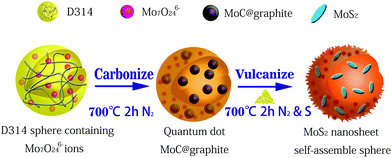
Polymethacrylate-based anion-exchange resins (D 314) were first rinsed with absolute ethanol for 10 hours to remove adsorbed organic components. The resins were then washed successively with 5% HCl, deionized water, and 5% NaOH solution three times. Subsequently, the wet resins were dried in a vacuum oven at 60 °C for 12 h. After soaking and stirring in 0.1 mol L−1 (NH4)6Mo7O24 solution for 6 h, the resins were cleaned with deionized water three times continuously to wash away redundant ions from their surfaces.21,22Thereafter, the dried Mo-containing resins were transferred into a ceramic boat and annealed at a temperature of 700 °C for 2 h under a flow of inert atmosphere (150 mL min−1). After cooling to ambient temperature, the products were ground and sieved through a 80–140 mesh. Finally, MoS2/C nanocomposite was obtained by mixing the as-prepared MoC/C and sulfur powders, followed by the same calcining process mentioned above. The whole preparation procedure is schematically illustrated in Fig. 1.
Characterization
The crystallinity of samples was analyzed by a Siemens X-ray generator with Cu Kα radiation (λ = 0.15406 nm) in the range of 10–80°. Raman spectroscopy measurement was performed in a LabRAM HR 800 Raman microscope using an excitation laser beam with a wavelength of 532 nm. The specific surface areas of the sample were analyzed by nitrogen (N2) adsorption–desorption isotherms at 77 K using a NOVA 1200e Surface Area. Morphology characterization and energy dispersive spectrometry analysis of samples were carried out with a field-emission scanning electron microscope (SEM; Hitachi, S4800). Further characterization was obtained from a field-emission transmission electron microscope (TEM; JEOL Ltd, Tokyo, Japan) at 200 kV.Electrochemical measurements
The working electrode was prepared by mixing active material (80 wt%), acetylene black (10 wt%) and polyvinylidene difluoride (PVDF) (10 wt%) in N-methyl-2-pyrrolidone (NMP) solution to form a homogeneous slurry, which was then pasted uniformly onto copper foil and dried for 12 h at 120 °C. The half-cell was assembled in an Ar-filled glove box (Mbraun, H2O and O2 < 0.1 ppm) by taking the circular copper plate as a cathode, glass fiber as a separator and pure Na foil as an anode. The sodium foils were used as counter electrodes and reference electrodes. Glass fiber was applied as a separator. The electrolyte was composed of a solution of 1 M NaClO4 in ethylene carbonate (EC)–propylene carbonate (PC)–fluoroethylene carbonate (FEC) (EC![[thin space (1/6-em)]](https://www.rsc.org/images/entities/char_2009.gif) :
:![[thin space (1/6-em)]](https://www.rsc.org/images/entities/char_2009.gif) PC = 1
PC = 1![[thin space (1/6-em)]](https://www.rsc.org/images/entities/char_2009.gif) :
:![[thin space (1/6-em)]](https://www.rsc.org/images/entities/char_2009.gif) 1 volume ratio, FEC = 5 wt%). The electrochemical performances of the half cells were characterized by cyclic voltammetry and galvanostatic charge–discharge.
1 volume ratio, FEC = 5 wt%). The electrochemical performances of the half cells were characterized by cyclic voltammetry and galvanostatic charge–discharge.
Results and discussion
Fig. 2 shows the X-ray diffraction (XRD) patterns of MoC/C and MoS2/C. The crystallographic structure of the MoC/C nanocomposite is displayed in Fig. 2b. All the diffraction peaks match well with those of a MoC standard (JCPD no. 65-0280), indicating high sample purity. The MoS2/C nanocomposite shows conspicuous, sharp peaks at 14.2°, 32.9° and 39.5° (Fig. 2a), which are indexed as (002), (100) and (103) facets of MoS2 (JCPD no. 75-1539), indicating that the prepared samples have high crystallinity. Any small impurity peaks are negligible.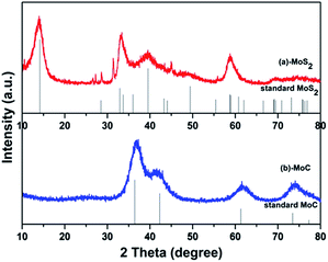 | ||
| Fig. 2 XRD patterns of prepared (a) MoC/C nanocomposite and MoC standard, and (b) MoS2/C nanocomposite and MoS2 standard. | ||
Raman spectra provide an easy, qualitative characterization of MoS2 nanosheets (Fig. 3a). The typical peak, known as the E2g1, originates from the in-plane vibration of Mo–S, and an A1g peak from out-of-plane vibrations is also observed.20,23 Meanwhile, two distinguishable peaks are observed at 1345 and 1590 cm−1, which can be ascribed to the D-band and G-band of carbon, respectively. The peak intensity ratio (ID/IG) is a useful index for the degree of crystallinity of carbon materials. The smaller the ratio, the higher the degree of ordering.24 As shown in Fig. 3b, the specific surface area of the as-prepared MoS2 nanosheets is calculated by the conventional Brunauer–Emmett–Teller (BET) method, and is approximately 59.34 m2 g−1. We also performed the XPS measurements. In Fig. 3c, the Mo 3d peaks are assigned to Mo4+ 3d5/2 (229.3 eV) and Mo4+ 3d3/2 (232.6 eV), which are expected values for Mo4+ in the MoS2. The corresponding S 2p peak consists of a single doublet of 2p1/2 (163.4 eV) and S 2p3/2 (162.3 eV), consistent with the S2− type present in MoS2 (Fig. 3d). It shows a small peak at around 236 eV, which corresponds to Mo6+ 3d5/2 from Mo oxidation.25
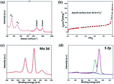 | ||
| Fig. 3 (a) Raman spectra of MoS2/C, (b) N2 adsorption/desorption isotherms of MoS2/C, (c) Mo 3d and (d) S 2p XPS spectra of the MoS2 nanosheets. | ||
The SEM and TEM images of MoS2/C are shown in Fig. 4. The SEM images (Fig. 4a), show the samples to be clustered together with a flower-like morphology. Each cluster is approximately 200 nm in diameter. The energy dispersive spectrum further confirms the existence of Mo, S, and C. Fig. 4c and d show the TEM and HRTEM images of MoS2/C. It is clear that each cluster consists of a large number of MoS2 nanosheets, which are located in the carbon matrix. These ultrathin nanosheets have lengths of 20 nm and widths of 10 nm. Distinct diffraction rings are visible in the inset of Fig. 4c, and the clear lattice fringes with 0.63 nm spacing (Fig. 4d) indicate that the MoS2 is well crystallized. The graphitic carbon layer of the composites is about 3 nm, and it is clearly to see the lattice fringes of graphite.
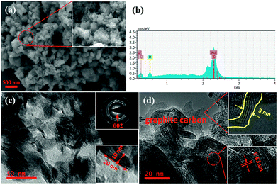 | ||
| Fig. 4 MoS2/C nanocomposite characterized by (a) SEM image, (b) energy dispersive spectrum, (c) TEM images, and (d) HRTEM image. | ||
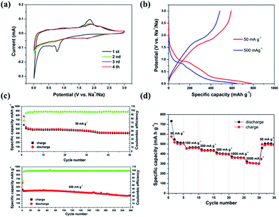
Fig. 5a displays a typical CV curve of the MoS2/C nanocomposite in the potential window of 0.01–3.0 V. Three reduction peaks in the first sodiation process are observed, situated at 1.77, 0.82, and 0.12 V, respectively. The reduction peak at 1.7 V is attributed to the insertion of Na+ into MoS2, forming NaxMoS2.26,27 The next reduction peak, at 0.82 V, is related to the further insertion of Na+ in combination with the formation of an interphase layer of solid electrolyte. The sharp peak at 0.15 V indicates a conversion reduction (NaxMoS2 + Na+ → Mo + NaxS).20,28 In the following oxidation curve, the peak near 1.85 V corresponds to desodiation. Interestingly, the 2nd, 3rd and 4th CV curves nearly overlap, indicating good reversibility and predominance of storage reduction. We can attribute the high reversibility and stability of sodiation/disodiation to the layered structure of MoS2 nanosheets, and to the porous graphitic carbon which possesses sufficient space to provide structural stability, effectively preventing the structure from collapsing and disintegrating.
The galvanostatic discharge/charge behavior of the MoS2/C nanocomposite was measured at currents of 50 mA g−1 and 500 mA g−1, respectively. As shown in Fig. 5b, the first discharge process contains correlative plateau regions that are identified to the CV profiles. The initial discharge/charge capacities of the MoS2/C nanocomposite at 50 mA g−1 are 784.3 and 590.0 mA h g−1, respectively, with a coulombic efficiency of 75.5%. At the current density of 500 mA g−1, the initial discharge/charge capacities are 646.4 and 484.8 mA h g−1, corresponding to a coulombic efficiency of 75%. Fig. 5c further exhibits the cycling performance of the MoS2/C nanocomposite. Apparently, the as-prepared sample demonstrates good cycle retention at both current densities of 50 mA g−1 and 500 mA g−1. The discharge capacity is maintained at 418.8 mA h g−1 at 50 mA g−1 after 50 cycles. Even at bigger current density of 500 mA g−1, it can still remain the capacity of 295.0 mA h g−1 after 260 cycles. As expected, the MoS2/C nanocomposite also exhibits excellent rate capacity (Fig. 5d). When the current density is increased from 50 mA g−1 to 2000 mA g−1, it simultaneously displays promising specific capacities and rate capabilities. The reversible capacities at 50, 100, 200, 500, 1000, 2000 mA g−1 are 513.1, 467.3, 437.1, 399.2, 361.8, 302.7 mA h g−1, respectively. Importantly, when the current density resumes to 50 mA g−1 after cycling at different rates, a capacity of 505.7 mA h g−1 is still achieved. This further confirms the stable structure of the nanosheet-based hybrid and its excellent reversibility.
Conclusions
In this study, a novel and simple method is proposed for preparation of layered MoS2/C nanosheets by calcining sulfur powders and MoC/C hybrids in an inert atmosphere. The MoC/C hybrids were synthesized from an ion-exchange, resin-adsorbing solution containing heavy metal salts. Based on the above characterization, results and electrochemical investigations, the MoS2/C composite displayed satisfactory electrochemical performance and structural integrity. The MoS2/C nanocomposite was composed of ultrathin nanosheets (≈10 nm) uniformly distributed on a porous conductive carbon matrix. This structure not only provides sufficient ionic and electronic transport, but also mitigates mechanical stress on MoS2 during discharge and charge. Meanwhile, the confined, ultrathin, layered MoS2 nanosheets can effectively inhibit aggregation and facilitate electrode reactions. The synergetic effect of MoS2 nanosheets with a porous carbon matrix results in outstanding properties – even after 50 cycles, the capacity remains at 418.8 mA h g−1 with a current density of 50 mA g−1, and at 300.4 mA h g−1 with a current density of 500 mA g−1. This strategy presented in this paper may also improve the electrochemical performance of other metal sulfides with potential for use as sodium-ion battery anodes.Acknowledgements
This work was financially supported by the National Natural Science Foundation of China (No. 21671096 and 21603094), the Shenzhen Peacock Plan (No. KQCX20140522150815065), the Natural Science Foundation of Shenzhen (No. JCYJ20150630145302231, No. JCYJ20150331101823677), and the Science and Technology Innovation Foundation for the Undergraduates of SUSTech (2015x19 and 2015x12). Y. G. T thanks the support from the National Natural Science Foundation of China (No. 21271187).Notes and references
- P. Poizot, S. Laruelle, S. Grugeon, L. Dupont and J. Tarascon, Nature, 2000, 407, 496–499 CrossRef CAS PubMed.
- M. D. Slater, D. Kim, E. Lee and C. S. Johnson, Adv. Funct. Mater., 2013, 23, 947–958 CrossRef CAS.
- V. Palomares, P. Serras, I. Villaluenga, K. B. Hueso, J. Carretero-González and T. Rojo, Energy Environ. Sci., 2012, 5, 5884–5901 CAS.
- H. Pan, Y. S. Hu and L. Chen, Energy Environ. Sci., 2013, 6, 2338–2360 CAS.
- Q. Sun, Q. Q. Ren, H. Li and Z. W. Fu, Electrochem. Commun., 2011, 13, 1462–1464 CrossRef CAS.
- L. Zhao, H. L. Pan, Y. S. Hu, H. Li and L. Q. Chen, Chin. Phys. B, 2012, 21, 028201 CrossRef.
- D. Stevens and J. Dahn, J. Electrochem. Soc., 2000, 147, 4428–4431 CrossRef CAS.
- S. Komaba, Y. Matsuura, T. Ishikawa, N. Yabuuchi, W. Murata and S. Kuze, Electrochem. Commun., 2012, 21, 65–68 CrossRef CAS.
- R. Tenne, Adv. Mater., 1995, 7, 965–995 CrossRef CAS.
- (a) Y. Li, Z. Zhou, S. Zhang and Z. Chen, J. Am. Chem. Soc., 2008, 130, 16739–16744 CrossRef CAS PubMed; (b) H. Ramakrishna Matte, A. Gomathi, A. K. Manna, D. J. Late, R. Datta, S. K. Pati and C. Rao, Angew. Chem., 2010, 122, 4153–4156 CrossRef.
- (a) J. S. Kim, H. J. Ahn, H. S. Ryu, D. J. Kim, G. B. Cho, K. W. Kim, T. H. Nam and J. H. Ahn, J. Power Sources, 2008, 178, 852–856 CrossRef CAS; (b) A. Kitajou, J. Yamaguchi, S. Hara and S. Okada, J. Power Sources, 2014, 247, 391–395 CrossRef CAS; (c) D. Su, S. Dou and G. Wang, Chem. Commun., 2014, 50, 4192–4195 RSC; (d) B. Qu, C. Ma, G. Ji, C. Xu, J. Xu, Y. S. Meng, T. Wang and J. Y. Lee, Adv. Mater., 2014, 26, 3854–3859 CrossRef CAS PubMed.
- X. Huang, Z. Zeng and H. Zhang, Chem. Soc. Rev., 2013, 42, 1934–1946 RSC.
- Y. P. Lei, Q. Shi, C. Han, B. Wang, N. Wu, H. Wang and Y. D. Wang, Nano Res., 2016, 9, 2498–2509 CrossRef CAS.
- X. Xie, Z. Ao, D. Su, J. Zhang and G. Wang, Adv. Funct. Mater., 2015, 25, 1393–1403 CrossRef CAS.
- P. P. Wang, H. Sun, Y. Ji, W. Li and X. Wang, Adv. Mater., 2014, 26, 964–969 CrossRef CAS PubMed.
- S. H. Choi, Y. N. Ko, J. K. Lee and Y. C. Kang, Adv. Funct. Mater., 2015, 25, 1780–1788 CrossRef CAS.
- J. X. Liu, H. Cao, B. Jiang, Y. H. Xue, L. Fu, D. Hou and Y. Huang, Sci. China Mater., 2016, 59, 459–474 Search PubMed.
- C. Zhu, X. Mu, P. A. van Aken, Y. Yu and J. Maieret, Angew. Chem., Int. Ed., 2014, 53, 2152–2156 CrossRef CAS PubMed.
- G. S. Bang, K. W. Nam, J. Y. Kim, J. Shin, J. W. Choi and S. Y. Choi, ACS Appl. Mater. Interfaces, 2014, 6, 7084–7089 CAS.
- J. Wang, C. Luo, T. Gao, A. Langrock, A. C. Mignerey and C. S. Wang, Small, 2015, 11, 473–481 CrossRef CAS PubMed.
- P. Tao, J. Hu, W. Wang, S. Wang, M. Li, H. Zhong, Y. Tang and Z. Lu, RSC Adv., 2014, 4, 13518–13524 RSC.
- J. Hu, P. Tao, S. Wang, Y. Liu, Y. Tang, H. Zhong and Z. Lu, J. Mater. Chem. A, 2013, 1, 6558–6562 CAS.
- H. S. Lee, S. W. Min, Y. G. Chang, M. K. Park, T. Nam, H. Kim, J. H. Kim, S. Ryu and S. Im, Nano Lett., 2012, 12, 3695–3700 CrossRef CAS PubMed.
- S. Urbonaite, L. Hälldahl and G. Svensson, Carbon, 2008, 46, 1942–1947 CrossRef CAS.
- G. S. Bang, K. W. Nam and J. Y. Kim, ACS Appl. Mater. Interfaces, 2014, 6, 7084–7089 CAS.
- L. David, R. Bhandavat and G. Singh, ACS Nano, 2014, 8, 1759–1770 CrossRef CAS PubMed.
- Z. Hu, Q. N. Liu, W. Y. Sun, W. J. Li, Z. L. Tao, S. L. Chou, J. Chen and S. X. Dou, Inorg. Chem. Front., 2016, 3, 532–535 RSC.
- Z. Hu, L. Wang, K. Zhang, J. Wang, F. Cheng, Z. Tao and J. Chen, Angew. Chem., 2014, 126, 13008–13012 CrossRef.
Footnote |
| † These authors contributed equally. |
| This journal is © The Royal Society of Chemistry 2017 |

