
 Open Access Article
 This Open Access Article is licensed under a Creative Commons Attribution-Non Commercial 3.0 Unported Licence
Synthesis of titanosilicate pillared MFI zeolite as an efficient photocatalyst
Laleh Emdadia,
Dat T. Tranb,
Junyan Zhanga,
Wei Wua,
Haomin Songc,
Qiaoqiang Ganc and
Dongxia Liu *a
*a
aDepartment of Chemical and Biomolecular Engineering, University of Maryland, College Park, 4418 Stadium Dr., College Park, MD 20742, USA. E-mail: liud@umd.edu
bRDRL-SEC-C, US Army Research Laboratory, 2800 Powder Mill Road, Adelphi, MD 20783, USA
cDepartment of Electrical Engineering, University at Buffalo, 230 M Davis Hall, Buffalo, NY 14260, USA
First published on 16th December 2016
Abstract
A titanosilicate pillared MFI zeolite (abbreviated as Si/Ti-PMFI) has been synthesized by sequential infiltration of a mixed tetraethyl orthosilicate (TEOS) and tetrabutyl orthotitanate (TBOT) solvent into and hydrolysis of the TEOS/TBOT solvent entrapped between the multilamellar MFI layers. The Ti-species present in the titanosilicate pillars, acid sites supplied by the framework Al–O(H)–Si sites in MFI layers, and mesoporosity collectively endow Si/Ti-PMFI with efficient adsorption assisted photocatalytic functionality, which was exemplified by the degradation of methyl orange (MO) in water. The synthesis of Si/Ti-PMFI zeolites containing Al–O(H)–Si acid sites within MFI layers and Ti-sites between layers diversified the structure, physicochemical properties, and catalytic functionality of hierarchical lamellar zeolites. The Si/Ti-PMFI lamellar zeolites were studied as adsorptive catalysts for photocatalysis, especially when bulky molecules are involved.
Introduction
Zeolites have wide applications as solid catalysts in many chemical and petrochemical processes because of their unique properties such as high surface area, high adsorption capacity, and well-defined micropores that are responsible for shape selectivity.1–5 The relatively small size of micropores (typically less than 2 nm), however, limits the catalytic performance of the zeolites and induces low catalyst utilization when the reaction of bulky molecules is concerned.6–8 Inclusion of the mesoporosity to the microporous zeolites, i.e., synthesis of hierarchical meso-/microporous zeolites, is a strategy to improve the catalyst utilization by promoting active site accessibility and mass transport for reactions involving bulky molecules.7,9–11Different methods have been developed to create hierarchical meso-/microporous zeolites during the past decade.12–17 Synthesis of two-dimensional (2D) layered zeolites followed by pillaring of the resulted 2D structures is an example of these synthesis methods.18–22 The guest species can be intercalated between interlayer spacing of 2D zeolites to preserve their ordered layered structure. The void space created between the layers forms a mesopore system in 2D zeolites. As a result, new structural and physicochemical properties can be introduced into the 2D hierarchical meso-/microporous zeolites in addition to their intrinsic microporous features.23–25
MCM-36, reported by Mobil scientists in 1990's,19 is the first pillared 2D zeolite. In the synthesis of MCM-36, a layered precursor, MCM-22 (P), was intercalated by silica species, which led to silica pillared meso-/microporous MCM-36 zeolite, with micropores within the zeolitic layers and mesopores between the layers. In recent years, the layered precursor versions of other zeolite frameworks such as FER,26–28 SOD,29 MFI,13 and IPC30,31 have been synthesized. Silica pillared 2D structures built from these frameworks have been demonstrated, most notable structures like ITQ-36 (silica pillared FER)26 and pillared MFI21 zeolites. In addition, pillaring of the 2D zeolites with inorganic compounds other than silica material has been reported.18,32–34 For example, alumina and magnesia–alumina have been applied for pillaring of the MCM-22 (P), which resulted in production of MCM-36 with variable acid–base and ion-exchange properties.33
Advancing the derivatives of 2D zeolites that contain Ti-species will create opportunities for endowing these materials with new structural and catalytic properties. The active sites from Ti-species are grafted on the external surface or encapsulated between the 2D zeolite layers, together with the hierarchical meso-/microporosity in the zeolites, are expected to expand the application of 2D zeolites for a range of oxidation and photocatalytic reactions. The Ti-species have been introduced onto ITQ-2 zeolite by anchoring the titanocene precursor on the external surface of ITQ-2 material,35 a delaminated format of the pure siliceous MWW polymorph (ITQ-1).36 The resultant Ti/ITQ-2 zeolite enabled efficient reactions for epoxidation of olefins.37 Similarly, Ti-species from the tetrabutyl orthotitanate (TBOT) precursor have been placed on the external surface of 2D MFI zeolite, which exhibited as excellent catalyst for epoxidation of bulky olefins.38 The 2D zeolite with Ti-containing pillars (i.e., titanosilicate pillared MCM-36) has also been recently synthesized by pillaring of MCM-22 (P) or ERB-1 (borosilicate and aluminum-free analogue of MCM-22 (P)) with a mixed tetraethyl orthosilicate (TEOS) and TBOT solvent.39,40 The same protocol has been applied to synthesis of titanosilicate pillared multilamellar titanium containing siliceous MFI (TS-1) zeolites.41 The resultant samples were active catalysts for either epoxidation of organic molecules39–41 or selective oxidation of bulky organic sulphides.42 To the best of our knowledge, the synthesis of titanosilicate pillared lamellar MFI zeolite with Al–O(H)–Si acid sites within microporous MFI layers has not been reported. Additionally, the application of the Ti-containing derivatives of 2D lamellar zeolites as catalysts for photocatalytic reactions has not been explored.
In this work, we aim to synthesize a titanosilicate pillared MFI (designated as Si/Ti-PMFI) zeolite and explore its application as a catalyst for photocatalytic reactions. The precursor of Si/Ti-PMFI is 2D multilamellar MFI, prepared using the method reported in Ryoo's group.13 The pillaring of 2D multilamellar MFI zeolite was carried out using a mixed TEOS and TBOT solvent, following a recent reported method for pillaring of multilamellar TS-1 zeolite.41,42 The TEOS/TBOT solvent was infiltrated into the gallery between two adjacent MFI zeolite nanosheet layers and was converted into titanosilicate pillars through the consecutive hydrolysis and calcination steps. The morphology and physicochemical properties of Si/Ti-PMFI zeolites were characterized. The photocatalytic degradation of methyl orange (MO) due to the presence of Ti-species in titanosilicate pillars and Al–O(H)–Si acid sites in MFI layers was studied to exemplify the application of 2D Si/Ti-PMFI catalysts in photocatalytic water treatment.
Experimental section
Materials
Titanium(IV) n-butoxide (TBOT, 99+% purity) and methyl orange (C14H14N3NaO3S) were supplied by Alfa Aesar. Tetraethyl orthosilicate (TEOS, 98% purity), sodium hydroxide (NaOH, ≥97.0% purity, pellets), sulfuric acid (H2SO4, 95.0–98.0%), ammonium nitrate (NH4NO3, ≥99.0%), and titanium(IV) oxide (P25 titania ≥99.5% trace metal basis) were purchased from Sigma-Aldrich. Aluminum sulfate hydrate (Al2(SO)4·16H2O, 98.0–102.0%) was supplied by Mallinckrodt Chemicals. Deionized (DI) water was used throughout the experiment. Diquaternary ammonium surfactant ([C22H45–N+(CH3)2–C6H12–N+(CH3)2–C6H13]Br2, (C22–6–6)) was synthesized based on the reported method13 and the synthesis procedure has also been explained in our previous publications.43,44Synthesis of multilamellar MFI precursor
The Si/Ti-PMFI zeolite was synthesized from the multilamellar MFI precursor (designated as 2D MFI (P)), which was prepared following the recipe reported by Choi et al.13 Typically, the synthesis was performed by dissolving 0.7 g NaOH into 3.1 g DI water, dissolving 0.4 g H2SO4 in 4.2 g DI water, and subsequently adding the basic solution dropwise to the acidic solution under vigorous stirring. After cooling the mixture to ambient temperature, 0.19 g Al2(SO4)3·16H2O was dissolved in the mixture. Then, 6.3 g TEOS was added to the mixture and the mixture was stirred vigorously at room temperature for 20 h using a magnetic stirrer. Finally, this solution was mixed with a C22–6–6 solution that was prepared by dissolving 2.2 g C22–6–6 in 15 g DI water at 333 K. After continuous mixing for 2 h at room temperature, the resultant gel was transferred into a Teflon-lined stainless-steel autoclave, followed by crystallization for 5 days by tumbling the autoclave vertically at 30 rpm in an oven heated at 423 K. After crystallization, the zeolite product was filtered, washed with DI water, and dried at 343 K overnight.Pillaring of multilamellar MFI precursor
The pillaring of 2D MFI (P) was carried out by dispersing the precursor in a mixed TEOS and TBOT solvent, in which TEOS/TBOT molar ratio was varied from 5![[thin space (1/6-em)]](https://www.rsc.org/images/entities/char_2009.gif) :1, 20:1 to 40:1, respectively. For comparison purpose, the pillaring in sole TEOS (TEOS/TBOT ratio = ∞) or TBOT (TEOS/TBOT ratio = 0) solvent was also conducted. In each case, the weight ratio between the pillaring solvent agent and 2D MFI (P) was controlled as 5. The resultant suspension was sealed in a flask under Ar atmosphere, heated to 351 K in an oil bath and kept at 351 K for 24 h. Finally, the solid sample was collected by filtration and dried under ambient condition.
:1, 20:1 to 40:1, respectively. For comparison purpose, the pillaring in sole TEOS (TEOS/TBOT ratio = ∞) or TBOT (TEOS/TBOT ratio = 0) solvent was also conducted. In each case, the weight ratio between the pillaring solvent agent and 2D MFI (P) was controlled as 5. The resultant suspension was sealed in a flask under Ar atmosphere, heated to 351 K in an oil bath and kept at 351 K for 24 h. Finally, the solid sample was collected by filtration and dried under ambient condition.
Synthesis of Si/Ti-PMFI zeolite
Hydrolysis of 2D MFI (P) that contains entrapped TEOS/TBOT solvent was carried out by dispersing the sample in an aqueous solution with pH of 8 adjusted by NaOH. The weight ratio of aqueous solution to solid sample was 10. After stirring the mixture at 313 K for 6 h, the sample was collected by centrifugation, washed with DI water, and then dried under ambient condition. Finally, the sample was calcined at 723 K for 6 h under N2 (100 mL min−1) and at 823 K for 12 h under air (100 mL min−1). The resultant pillared MFI was designated as xSi/Ti-PMFI, where x = 0, 5, 20, 40, and ∞, respectively, denoting for the Si/Ti molar ratio used in the mixed TEOS/TBOT solvent. For comparison purpose, the 2D MFI (P) was calcined using the same protocol as that of xSi/Ti-PMFI, which was named as 2D MFI. The titanium containing microporous TS-1 zeolite (Si/Ti ratio of 50) was prepared following a reported procedure.45 The as-synthesized samples were directly used as catalysts for photocatalytic reaction tests discussed above.To synthesize the proton-form (H+-form) titanosilicate pillared 2D Si/Ti-PMFI zeolites for photocatalytic reaction tests, a portion of the calcined Si/Ti-PMFI samples was ion-exchanged three times using 1 M aqueous NH4NO3 (weight ratio of zeolite to NH4NO3 solution = 1:10) at 353 K for 12 h, and subsequently, collected by centrifugation, washed with DI water three times, and dried at 343 K overnight. The second calcination was conducted at 823 K for 4 h in dry air (100 mL min−1, ultrapure, Airgas) to decompose the NH4+ cations to form the proton-form zeolite.
Catalyst characterization
Powder X-ray diffraction (XRD) patterns were recorded using a Bruker D8 Advance Lynx Powder Diffractometer (LynxEye PSD detector, sealed tube, Cu Kα radiation with Ni β-filter). Transmission electron microscopy (TEM) images were captured on a JEM 2100 LaB6 electron microscope. The argon (Ar) isotherms were measured at 87 K on an Autosorb-iQ analyzer (Quantachrome Instruments). Prior to the measurement, samples were evacuated overnight at 623 K and 1 mm Hg. Si, Ti, and Al contents of zeolite samples were determined by inductively coupled plasma optical emission spectroscopy (ICP-OES, Perkin Elmer Optima 7000). Diffuse reflectance (DR) ultraviolet-visible (UV-Vis) spectra were obtained using an Ocean Optics USB2000+ spectrometer equipped with an IS200-4 integrating sphere detector, and the white high reflectance sphere material (manufactured from polytetrafluoroethylene (PTFE) based bulk material) was used as the reference.Adsorption and photocatalytic decomposition of methyl orange
The liquid phase catalytic degradation of MO molecules under light irradiation was employed to examine the catalytic performance of the xSi/Ti-PMFI zeolites. The reaction set-up consisted of a 200 W HBO mercury (Hg) lamp (OSRAM, Germany) located next to a 50 mL quartz flask with the distance of 15 cm. In a typical experiment, 20 mL of 0.05 g L−1 MO aqueous solution was mixed with 0.02 g of zeolite in the flask. The mixture was stirred at 500 rpm in the darkness for 2 hours and then the Hg lamp was turned on. This moment of turning on the Hg lamp was taken as the initial reaction time and 2 hours of mixing time guaranteed that the adsorption reached saturation. Liquid samples were withdrawn at regular time intervals and analyzed by a Lambda 40 UV/Vis spectrophotometer (PerkinElmer Instruments) at the maximum absorption wavelength of MO, i.e., 468 nm.Results and discussion
Formation of Si/Ti-PMFI zeolites tracked by XRD patterns
To study the influences of TBOT content in the mixed TEOS and TBOT solvent on synthesis of Si/Ti-PMFI, the molar ratio of TEOS/TBOT was controlled at 0 (i.e., without TEOS in the mixed solvent), 5, 20, 40 and ∞ (i.e., without TBOT in the mixed solvent), respectively, in the pillaring process. Fig. 1 shows the XRD patterns of the Si/Ti-PMFI zeolites from variant TEOS/TBOT moieties. For comparison, the 2D MFI (P) and 2D MFI, i.e., multilamellar MFI before and after calcination treatment, respectively, were included in Fig. 1. The wide-angle XRD peaks (Fig. 1(B)) in spectra of 5Si/Ti-PMFI, 20Si/Ti-PMFI, and 40Si/Ti-PMFI are nearly the same as those in spectra of 2D MFI (P), 2D MFI, and ∞Si/Ti-PMFI, which are characteristics of a crystalline MFI zeolite.13,21 This indicates that the pillaring of 2D MFI (P) with mixed TEOS/TBOT solvent neither scarified the crystalline structure nor introduced new crystalline phase in the MFI zeolite. The XRD spectrum of 0Si/Ti-PMFI has the characteristic peaks of MFI and a new peak around 2θ = 25.4°. The new diffraction peak can be assigned to anatase phase (JCPDS file no. 84.1286) of titania, which suggests that Ti-species from the TBOT solvent were not completely converted into titanosilicate.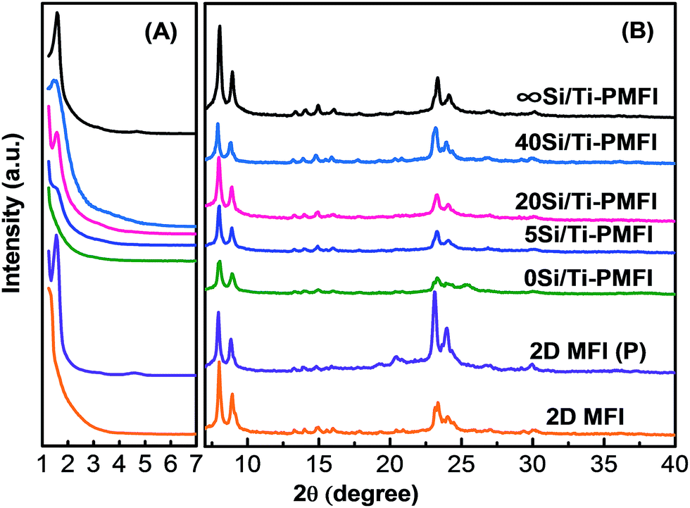 | ||
| Fig. 1 Low-angle (A) and wide-angle (B) XRD patterns of the synthesized 0Si/Ti-PMFI, 5Si/Ti-PMFI, 20Si/Ti-PMFI, 40Si/Ti-PMFI, and ∞Si/Ti-PMFI samples, respectively. 2D MFI (P) and 2D MFI have been shown here for comparison purpose. | ||
The diffraction peaks in the low-angle range of XRD spectra (Fig. 1(A)) demonstrate the interlamellar structural coherence of the 2D MFI layers in the Si/Ti-PMFI samples. The 2D MFI (P) exhibits two low-angle peaks at 2θ = 1.54° and 4.58°, respectively, which are assigned to the first- and third-order reflections in the multilamellar MFI zeolite.21 The removal of the C22–6–6 template by calcination in 2D MFI (P) led to collapse of the ordered MFI layers, indicated by the disappearance of low-angle diffraction peaks in 2D MFI in Fig. 1(A). The silica pillared multilamellar MFI (∞Si/Ti-PMFI) apparently retained the long-range ordering of the nanosheet layers in 2D MFI (P) since two diffraction peaks at 2θ = 1.57° and 4.65°, respectively, were observed. The pillaring of 2D MFI (P) with the solvent consisting of TBOT precursor resulted in different features in the low-angle XRD spectra of the Si/Ti-PMFI samples. For example, the low-angle XRD peak was absent in 0Si/Ti-PMFI (Fig. 1(A)), which hints the failure in pillaring of 2D MFI (P) zeolite with TBOT alone. With a decrease in TBOT quantity in the mixed TEOS/TBOT solvent in the pillaring process, the low-angle XRD peaks start to appear and their intensities increase. For example, 5Si/Ti-PMFI shows an obscure peak at 2θ ∼ 1.5° compared to 20Si/Ti-PMFI and 40Si/Ti-PMFI, but more obvious than 0Si/Ti-PMFI. The 20Si/Ti-PMFI and 40Si/Ti-PMFI show the clear low-angle diffraction peaks in Fig. 1(A), indicating that the long-range structural ordering of MFI nanosheet layers was well preserved in these two Si/Ti-PMFI samples.
The XRD data in Fig. 1 suggest that TBOT alone is not an efficient solvent for synthesis of Si/Ti-PMFI zeolite. On the contrary, TEOS is very suitable for pillaring of 2D MFI (P) zeolite. In the mixed TEOS/TBOT solvent, the decrease in the concentration of TBOT leads to an improvement in preservation of the long-range structural ordering of zeolite nanosheets in Si/Ti-PMFI. It should be noted that TBOT is bulkier in the molecular configuration and more viscous than TEOS. Both factors could contribute to the failure in synthesis of pillared 0Si/Ti-PMFI zeolite. The successful synthesis of Si/Ti-PMFI with mixed TEOS/TBOT solvent demonstrates that the molecular size of TBOT is not a barrier for incorporation of Ti-moiety into Si/Ti-PMFI. The mixed TEOS/TBOT solvent has lower viscosity than TBOT, which facilitates the infiltration of the solvent into gallery space of 2D MFI (P) and thus results in the successful synthesis of Si/Ti-PMFI zeolites. Similar results have been reported for synthesis of titanosilicate pillared MCM-36 by pillaring of MCM-22(P) or ERB-139 and titanosilicate pillared TS-1 lamellar zeolites41 using the mixed TEOS/TBOT solvent.
Textural properties of Si/Ti-PMFI zeolites
Fig. 2 shows the Ar isotherms and pore size distributions of the Si/Ti-PMFI zeolites. At the relatively low pressures (P/P0 < 0.02) in Fig. 2(A), all the Si/Ti-PMFI samples together with 2D MFI have similar Ar uptakes, which indicates all the presently studied zeolite samples have similar microporosity. The micropore surface areas (Smicro) and volumes (Vmicro) in Table 1 confirm the similarity in microporosity of these zeolites. At a higher relative pressure range (0.02 < P/P0 < 0.9), the Ar adsorption volume was increased in the order of 2D MFI ∼ 0Si/Ti-PMFI ≪ 5Si/Ti-PMFI < 20Si/Ti-PMFI < 40Si/Ti-PMFI < ∞Si/Ti-PMFI. The increase in Ar uptake in this pressure range indicates the increasing of mesoporosity in these samples. The external surface areas (Sext) and total pore volumes (Vt) of these samples in Table 1 indicate that the mesoporosity increases following the above rank of these samples.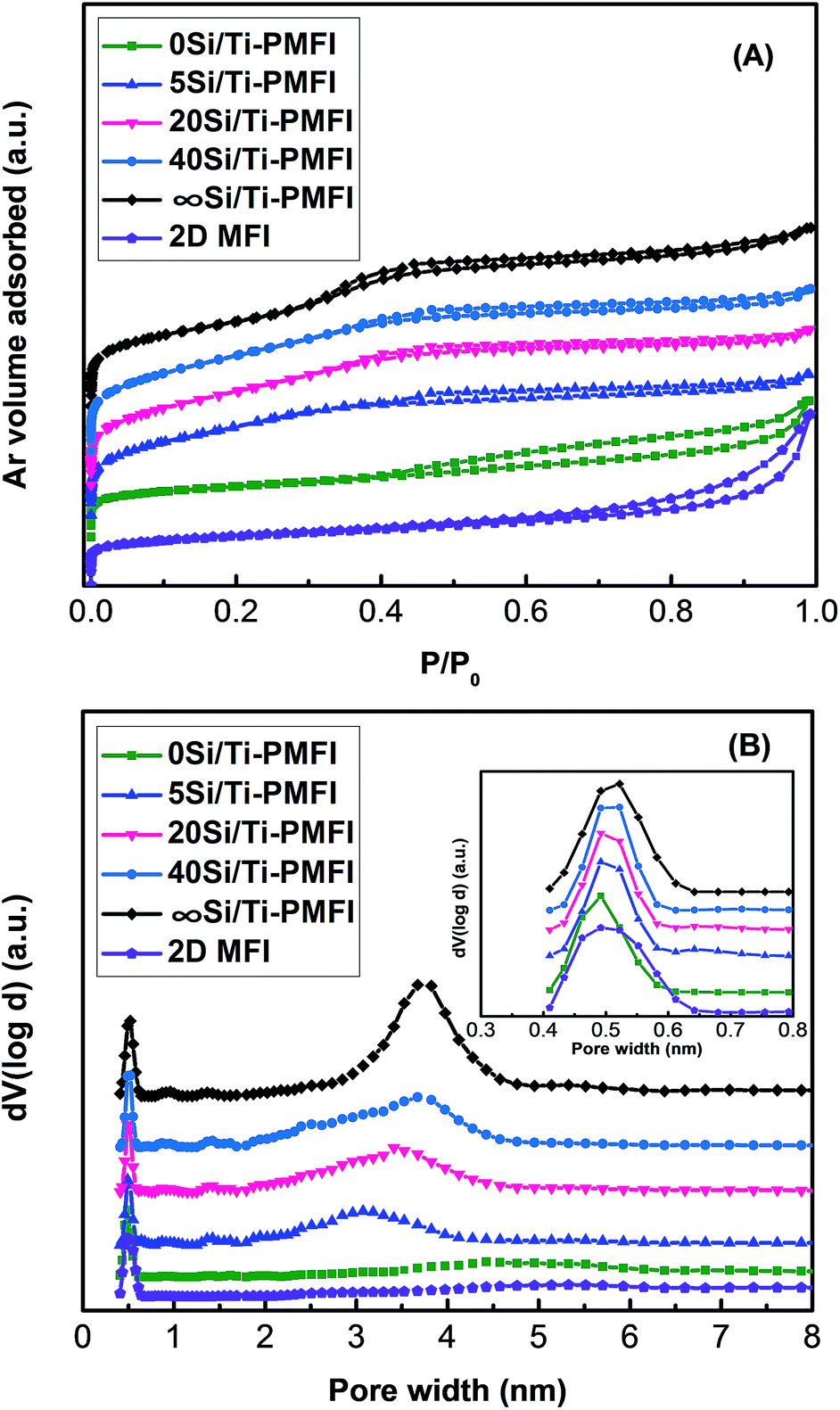 | ||
| Fig. 2 Ar isotherms (A) and the corresponding NLDFT pore size distributions (B) of 0Si/Ti-PMFI, 5Si/Ti-PMFI, 20Si/Ti-PMFI, 40Si/Ti-PMFI, ∞Si/Ti-PMFI, and 2D MFI samples, respectively. The inset image in (B) shows the NLDFT micropore size distributions. | ||
| Zeolite | Vmicroa (cm3 g−1) | Smicroa (m2 g−1) | Sexta (m2 g−1) | Vtb (cm3 g−1) | Vmesoc (cm3 g−1) | SBETd (m2 g−1) |
|---|---|---|---|---|---|---|
| a Determined from t-plot method.b Determined by NLDFT method.c Determined from Vmeso = Vt − Vmicro.d Determined from Brunauer, Emmett, and Teller (BET) method. | ||||||
| 2D MFI | 0.063 | 141 | 169 | 0.28 | 0.21 | 310 |
| 0Si/Ti-PMFI | 0.058 | 88 | 195 | 0.39 | 0.33 | 284 |
| 5Si/Ti-PMFI | 0.087 | 125 | 420 | 0.44 | 0.35 | 547 |
| 20Si/Ti-PMFI | 0.067 | 100 | 476 | 0.45 | 0.38 | 576 |
| 40Si/Ti-PMFI | 0.079 | 84 | 505 | 0.47 | 0.40 | 589 |
| ∞Si/Ti-PMFI | 0.060 | 89 | 520 | 0.54 | 0.48 | 609 |
The non-local density functional theory (NLDFT) pore size distributions in Fig. 2(B) further underscore the changes in the textural properties of the Si/Ti-PMFI zeolites. The plots in Fig. 2(B) were determined from the adsorption branches of Ar isotherms using cylindrical-type pore and silica adsorbent model. All the zeolite samples exhibit a similar strong and sharp peak centered at about 0.54 nm (inset in Fig. 2(B)), which is attributed to the 10-membered ring micropores of MFI zeolite.46 Additionally, broad peaks in the range of 2–5 nm with different intensities are seen for these zeolite samples, reflecting the existence of different mesoporosities. The 0Si/Ti-PMFI has a broad and less intense peak, analogous to that of 2D MFI, suggesting the failure in pillaring of the 2D MFI (P) using TBOT alone. The peak corresponding to mesopores in Fig. 2(B) becomes narrower and sharper when the material transits from 5Si/Ti-PMFI, 20Si/Ti-PMFI, and 40Si/Ti-PMFI to ∞Si/Ti-PMFI. This reflects the increase in mesopore volume and uniformity of mesopore sizes with decreasing TBOT content in the mixed solvent in the synthesis.
The textural property analysis of Si/Ti-PMFI zeolites indicates that the preservation of mesoporosity (i.e., the ordered layered structure of the 2D MFI (P)) is directly correlated to the TBOT content in the mixed TEOS/TBOT solvent. The similarity in micropore sizes and volumes of these Si/Ti-PMFI zeolites to those of 2D MFI suggests that neither TBOT nor TEOS influences micropores of MFI zeolite. It has been reported that both of these molecules are too bulky to enter the 10-membered rings of MFI zeolite.47,48 The presence of significant mesoporosity in 20Si/Ti-PMFI and 40Si/Ti-PMFI zeolites demonstrates that both TEOS and TBOT can enter the galleries of 2D MFI (P) to form titanosilicate pillars. The higher mesopore volume and external surface area of Si/Ti-PMFI zeolites, obtained by increasing the TEOS/TBOT molar ratio in the mixed solvent, confirm the increase in intercalation efficiency of titanosilicate pillars into 2D MFI (P) when the viscosity of the mixed solvent is reduced in the synthesis.
Composition of pillars in Si/Ti-PMFI zeolites
The Si, Al, and Ti compositions of the Si/Ti-PMFI and 2D MFI zeolites were studied, and the results are included in Table 2. By direct comparison of elemental compositions between Si/Ti-PMFI and 2D MFI zeolites, the compositions of the pillars introduced were evaluated. As shown in Table 2, 2D MFI zeolite has a Si/Al ratio of 49, corresponding to 16.3 mmol SiO2 units per gram of 2D MFI. The Si/Al of ∞Si/Ti-PMFI was increased to 63 (equivalent to 21 mmol SiO2 per gram of zeolite). The increase of Si/Al ratio from 49 to 63 corresponds to 4.7 mmol SiO2 per gram of 2D MFI incorporated as pillars in ∞Si/Ti-PMFI. The weight fraction of SiO2 pillars can then be evaluated, which constitutes of 22 wt% of ∞Si/Ti-PMFI. Similar analysis was conducted for Si/Al ratio of 74 in 40Si/Ti-PMFI, 69 in 20Si/Ti-PMFI, 59 in 5Si/Ti-PMFI, and 48 in 0Si/Ti-PMFI zeolite samples, respectively. Table 2 lists that 34 wt%, 29 wt%, 17 wt%, and 0 wt% of the Si/Ti-PMFI samples are SiO2 pillars from TEOS solvent in the pillaring of 2D MFI (P) zeolite.| Zeolite | Bulk composition | Composition of pillars in zeolites | ||||||
|---|---|---|---|---|---|---|---|---|
| Si/Al ratioa | Si/Ti ratioa | SiO2b (mmol g−1) | SiO2 pillarc (mmol g−1) | SiO2 pillard (wt%) | TiO2 pillare (wt%) | Si/Ti ratiof | TEOS/TBOT ratiog | |
| a Determined by ICP-OES analysis.b SiO2 concentration in zeolite calculated from Si/Al ratio.c Concentration of SiO2 pillar in the Si/Ti-PMFI zeolite, calculated from the difference of SiO2 concentration in pillared zeolite from that in 2D MFI.d Weight percentage of SiO2 units that constitute of pillars in the Si/Ti-PMFI zeolite.e Weight percentage of TiO2 units that constitute of pillars in the pillared zeolite.f Molar ratio of Si/Ti in the pillars, evaluated by (weight of SiO2 in pillars/molecular weight of SiO2)/(weight of TiO2 in pillars/molecular weight of TiO2).g Molar ratio of TEOS/TBOT in the mixed solvent for pillaring of 2D MFI. | ||||||||
| 2D MFI | 49 | — | 16.3 | 0 | 0 | 0 | — | — |
| 0Si/Ti-PMFI | 48 | 4.3 | 16.0 | 0 | 0 | 31.0 | 0 | 0 |
| 5Si/Ti-PMFI | 59 | 22.6 | 19.7 | 3.3 | 17 | 6.0 | 4 | 5 |
| 20Si/Ti-PMFI | 69 | 61.0 | 23.0 | 6.7 | 29 | 2.2 | 18 | 20 |
| 40Si/Ti-PMFI | 74 | 118.0 | 25.0 | 8.3 | 34 | 1.1 | 40 | 40 |
| ∞Si/Ti-PMFI | 63 | — | 21.0 | 4.7 | 22 | 0 | ∞ | ∞ |
The Si/Ti ratio of each sample in Table 2 indicates that 1.1 wt%, 2.2 wt%, 6.0 wt%, and 31.0 wt% of TiO2 units exist in the 40Si/Ti-PMFI, 20Si/Ti-PMFI, 5Si/Ti-PMFI, and 0Si/Ti-PMFI zeolites, respectively, which were formed from TBOT in the pillaring process. The Si/Ti molar ratio in the pillars of Si/Ti-PMFI samples (if we assume all incorporated Si- and Ti-species formed as pillars), therefore, can be calculated. As shown in Table 2, the weight gains due to Si- and Ti-species from TEOS and TBOT solvents, respectively, increase with increasing TEOS or TBOT concentration in the mixed solvent. Compared to the TEOS/TBOT ratio, the Si/Ti ratio in the pillars of the resultant Si/Ti-PMFI zeolites is nearly the same or slightly lower. This indicates that TBOT has comparable or slightly higher tendency than TEOS to be intercalated into the multilamellar MFI structure.
Coordination environment of Ti-species in Si/Ti-PMFI zeolites
The DR UV-Vis spectra (Fig. 3) were used to identify the coordination environment of Ti-species in the Si/Ti-PMFI zeolites. For comparison, the DR UV-Vis spectra of P25 titania and TS-1 zeolite are included. The absence of obvious absorption band in ∞Si/Ti-PMFI is consistent with the absence of Ti-species in this zeolite. The framework Ti-species in TS-1 result in an obvious absorption band centered at ∼220 nm, which is assigned to the charge transfer from O2− to Ti4+ in the tetrahedral (Td) framework Ti-sites.39,49 The P25 exhibits an absorption band at ∼280 nm that is assigned to the charge transfer from O2− to Ti4+ in an octahedral (Oh) coordination.39,49 Using P25 and TS-1 as bases, the coordination environment of Ti-species in Si/Ti-PMFI zeolites was analyzed.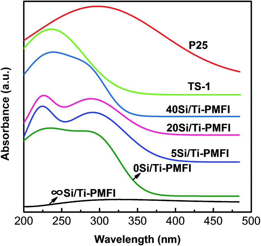 | ||
| Fig. 3 DR UV-Vis spectra of 0Si/Ti-PMFI, 5Si/Ti-PMFI, 20Si/Ti-PMFI, 40Si/Ti-PMFI, and ∞Si/Ti-PMFI samples, respectively. P25 and TS-1 samples are shown for comparison. | ||
Fig. 3 shows that the Si/Ti-PMFI samples have both absorption bands of P25 and TS-1, but the relative intensity of these two bands varies. The 0Si/Ti-PMFI sample has comparable absorption bands at ∼220 nm and ∼280 nm, but both peaks are blunt. This indicates that Ti-species in 0Si/Ti-PMFI zeolite have both tetrahedral and octahedral coordination, which is consistent with the presence of anatase phase indicted by XRD data above. The tetrahedrally coordinated Ti-species could be due to the formation of titanosilicate on the surface of 2D MFI (P) under assistance of C22–6–6 template in 2D MFI (P). The absorption band centered at ∼220 nm becomes stronger and sharper with the transition of the sample from 0Si/Ti-PMFI to 5Si/Ti-PMFI, 20Si/Ti-PMFI, and 40Si/Ti-PMFI, respectively. Oppositely, the absorption band centered at ∼280 nm decreases sequentially across these samples. As discussed for 0Si/Ti-PMFI, the presence of both bands indicates that both types of Ti-coordination exist in these zeolites. With an increase in TEOS content in the mixed solvent, more Ti-species are incorporated with tetrahedral coordination in Si/Ti-PMFI zeolites. For 40Si/Ti-PMFI zeolite, the majority of Ti-species are in the framework tetrahedral structure, similar to that of TS-1. The DR UV-Vis spectra suggest that Ti-species in the titanosilicate pillars are very likely crystallized into a MFI zeolite (or TS-1) structure. The tendency for building such a MFI-like pillar structure increases with increasing TEOS (or decreasing TBOT) content in the mixed solvent in the synthesis.
Morphology of Si/Ti-PMFI zeolites
To show the morphology of the Si/Ti-PMFI zeolites, we selected 20Si/Ti-PMFI sample and examined its morphology under TEM. The 2D MFI (P) sample was observed under TEM for comparison. The 2D MFI (P) (Fig. 4(A)) exhibits an ordered arrangement of lamellar MFI nanosheets. The lattice fringe can be clearly seen in the high-resolution TEM (HR-TEM) image of this sample (Fig. 4(B)).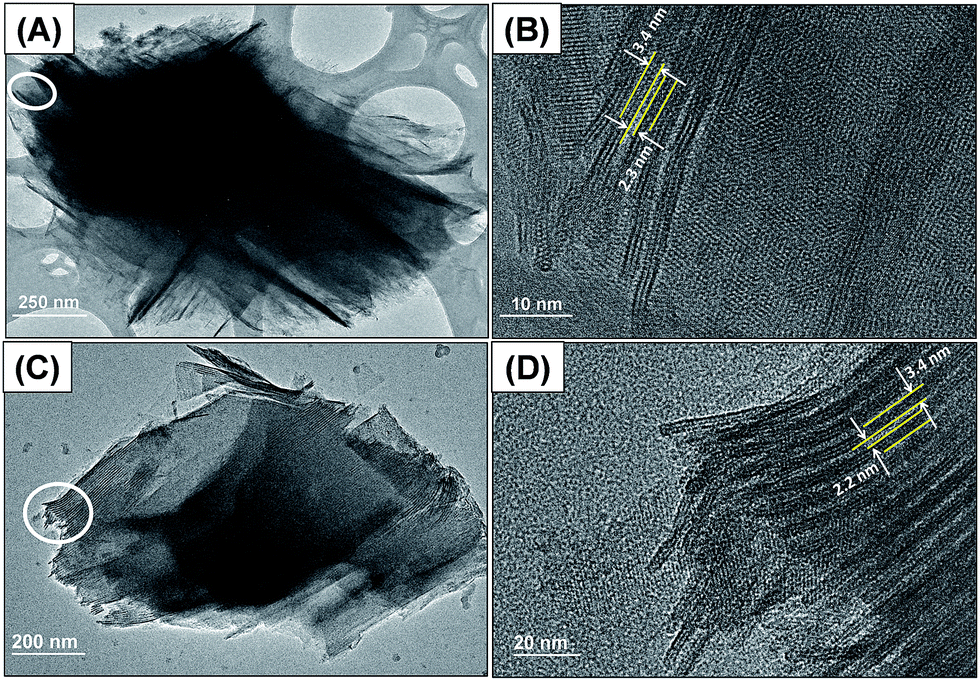 | ||
| Fig. 4 TEM images of the synthesized 2D MFI (P) (A and B) and 20Si/Ti-PMFI (C and D) samples ((B) and (D) show the high-resolution TEM (HR-TEM) images of the marked areas in (A) and (C), respectively). | ||
The multilamellar stacking of MFI nanosheets is composed of three pentasil sheets that are related to the 1.5 unit-cell dimension along the b-axis direction. The thickness of the single MFI zeolite nanosheet is around 3.4 nm, and the distance between neighboring MFI layers is ∼2.3 nm. Fig. 4(C) illustrates the plate-like particles of 20Si/Ti-PMFI. The HR-TEM image in Fig. 4(D) indicates that the incorporation of titanosilicate pillars into the layered space of 2D MFI (P) did not lead to collapse of the MFI zeolite nanosheets. The distance between the neighboring MFI layers was also ∼2.3 nm. The TEM observation confirms the interlamellar space between the MFI layers was preserved in the Si/Ti-PMFI zeolites.
Adsorption and photocatalytic performance of Si/Ti-PMFI zeolites
The removal of MO from water was used to evaluate the performance of Si/Ti-PMFI catalysts in adsorptive photocatalysis. The MO degradation rate (η) was indicated by the following equation:where C0 and C are the concentrations of MO (g L−1) before catalyst addition and at local reaction time, respectively. A0 and A are the corresponding absorbencies of MO aqueous solution under both conditions. Fig. 5(A) and (C) show the MO degradation rate versus reaction time for the Si/Ti-PMFI catalysts. The degradation of MO over TS-1 and P25 catalysts was also studied and shown in these figures. The influence of acidity from the framework Al–O(H)–Si sites in MFI layers on MO degradation was examined over H+-form Si/Ti-PMFI zeolites (Fig. 5(B) and (D)).

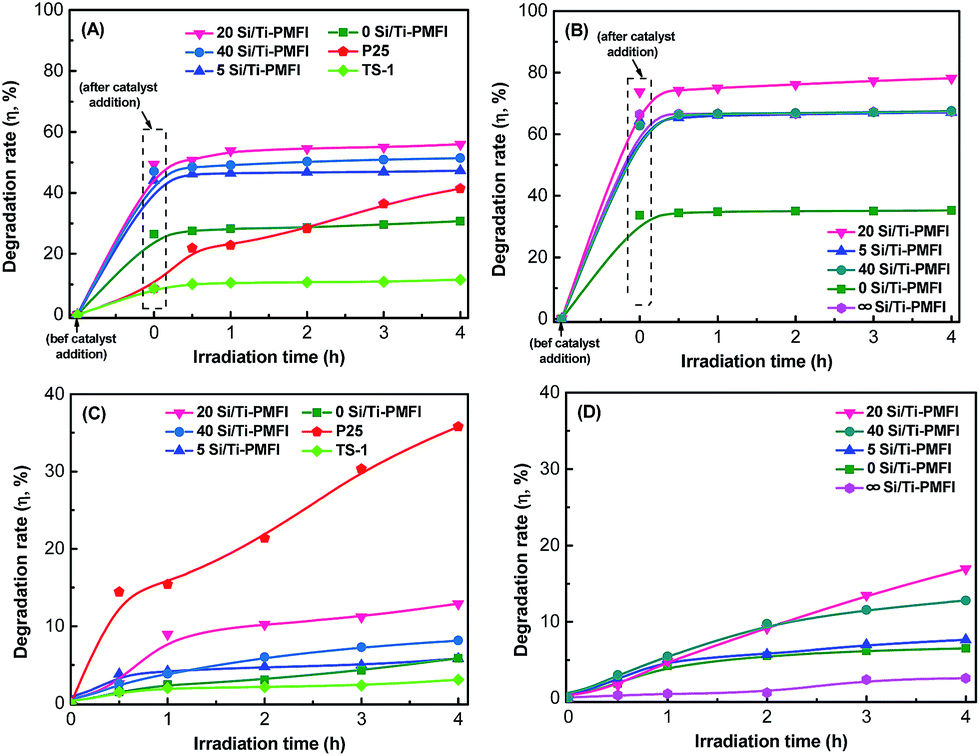 | ||
| Fig. 5 Methyl orange degradation rate (η) versus irradiation time over 0Si/Ti-PMFI, 5Si/Ti-PMFI, 20Si/Ti-PMFI, and 40Si/Ti-PMFI catalysts in the absence (A) and presence of Al–O(H)–Si sites (B), respectively. (C) and (D) display the photocatalytic contribution to the MO degradation over the catalysts shown in (A) and (B), respectively. Catalytic performances over P25 and TS-1 ((A) and (C)) and ∞Si/Ti-PMFI ((B) and (D)) were shown for comparison (0.02 g catalyst, room temperature, and 500 rpm stirring speed). | ||
As shown in Fig. 5(A), the addition of P25 catalyst into the MO aqueous solution caused ∼9% decrease in UV-Vis absorbance (or MO concentration), which suggests that P25 has low external surface area for MO adsorption in the reaction. Upon light irradiation, the MO degradation increased with reaction time, suggesting that P25 is an active catalyst for this reaction. TS-1 catalyst also showed almost similar adsorption of MO from the solution to that of P25, which means that the micropores of TS-1 are too small to allow MO molecules enter into them. The degradation rate of MO over TS-1 is much smaller compared to P25. This is mainly caused by the low number of Ti-sites in TS-1 (Si/Ti ratio = 50) catalyst. In comparison to P25 and TS-1 catalysts, all the Si/Ti-PMFI samples showed obvious adsorption that contributes to the degradation of MO molecules. For example, the 0Si/Ti-PMFI zeolite led to 26% MO degradation due to adsorption and 5.8% degradation after 4 hours of photocatalytic reaction. Similarly, 5Si/Ti-PMFI, 20Si/Ti-PMF, and 40Si/Ti-PMFI resulted in 44%, 49%, and 47% of MO adsorption and 5.9%, 12.9%, and 8.2% of MO degradation after 4 hours of reaction, respectively. It should be noted that 2 hours of mixing time before the light irradiation has allowed the adsorption to reach the saturation. The 2 hours of mixing time in the present study guaranteed the adsorption event is completed before the photocatalytic event takes place.
The performance of Si/Ti-PMFI zeolite (in the absence of Al–O(H)–Si acid sites) in photocatalytic degradation of MO molecules is directly related to two factors: the number of Ti-active sites and the accessibility of samples to bulky MO molecules. The composition analysis (Table 2) shows that the concentration of Ti-species in Si/Ti-PMFI zeolites increases with increasing TBOT quantity in the mixed TEOS/TBOT solvent in the synthesis process. The mesoporosity of the Si/Ti-PMFI zeolites (Fig. 2 and Table 1), however, exhibits an opposite trend. The consistency of the MO degradation rate with the mesoporosity of Si/Ti-PMFI zeolites suggests that mesoporosity plays more obvious role in MO degradation over these catalysts. The presence of mesoporosity enhanced the mass transport of bulky MO molecules into or product out of the pillared Si/Ti-PMFI zeolites, and thus facilitated the adsorption of MO molecules in the degradation process. The slightly higher degradation rate of MO over 20Si/Ti-PMFI than that of 40Si/Ti-PMFI should be due to the higher number of Ti-sites in the former sample since both catalysts have similar textural properties. The concentration of Ti sites in the Si/Ti-PMFI zeolites is ∼20–60 times lower than that of P25, and thus the lower photocatalytic activity was observed in these zeolite-based catalyst materials.
The presence of acid sites in the Si/Ti-PMFI zeolites apparently improved the adsorption capacities of these catalysts in MO degradation reactions. As shown in Fig. 5(B), 33%, 63%, 74%, and 64% of MO degradations due to adsorption were observed in 0Si/Ti-PMFI, 40Si/Ti-PMFI, 20Si/Ti-PMFI, and 5Si/Ti-PMFI, respectively. In comparison to MO adsorption over Si/Ti-PMFI catalysts in the absence of Al–O(H)–Si acid sites, the adsorption was enhanced by ∼20–40%. The photocatalytic degradation rate also increased (Fig. 5(D)). For example, the MO degradation reached 6.5%, 12.8%, 16.9% and 7.6%, respectively, over 0Si/Ti-PMFI, 40Si/Ti-PMFI, 20Si/Ti-PMFI, and 5Si/Ti-PMFI catalysts after 4 hours of reaction. For comparison, the MO degradation over ∞Si/Ti-PMFI zeolite (without Ti-site but with Al–O(H)–Si acid sites) was tested, which showed that 66% degradation was due to catalyst adsorption and had almost no photocatalytic degradation activity (∼2%) compared to the Ti-containing Si/Ti-PMFI zeolites. These results indicate that Al–O(H)–Si acid sites promoted adsorption and catalysis capabilities of Si/Ti-PMFI catalysts in MO degradation.
In photocatalytic degradation of organic molecules, it has been reported that pH value of an aqueous solution affects the reaction rate due to generation of the oxidizing species (˙OH, O2˙−, HO2˙, etc.) in the photocatalytic reaction systems.50,51 An aqueous solution with mild acidity (pH ∼ 5) has been reported to enable fast MO photocatalytic degradation over metal oxide catalysts.52,53 The Al–O(H)–Si acid sites in Si/Ti-PMFI zeolites form hydronium ions in aqueous MO solution, and thus are expected to influence the progress of the adsorption and reaction as observed on MO degradation in acidic solution. The enhancement in MO adsorption on the proton-form Si/Ti-PMFI might be due to the electrostatic interaction between the catalyst and MO molecules. The adsorption assisted photocatalysis in Si/Ti-PMFI zeolites is expected to be applicable to other types of reactions that deal with bulky molecules such as photocatalytic water or air treatment in environmental remedy.
Conclusions
The titanosilicate pillared MFI (Si/Ti-PMFI) zeolite was prepared by sequential dispersion of the multilamellar MFI precursor (2D MFI (P)) in the mixed TEOS and TBOT solvent, hydrolysis of entrapped solvent in 2D MFI (P), and calcination to form pillared zeolite structure. The Ti-species in the pillars of Si/Ti-PMFI zeolites enabled efficient photocatalytic reactions for MO degradation. The framework Al–O(H)–Si acid sites in MFI layers further accelerated the MO degradation rates by providing mild acidity for the reaction. The co-existence of Ti-species, Al–O(H)–Si acid sites, and mesoporosity in Si/Ti-PMFI zeolites enabled efficient adsorption and reaction of bulky molecules in photocatalysis. The synthesis of Si/Ti-PMFI zeolites diversifies the structural, physicochemical, and catalytic properties of 2D lamellar zeolites. The Si/Ti-PMFI lamellar zeolites are expected to be efficient catalysts for a range of reactions in adsorptive photocatalytic water and/or air treatments for environmental remedies.Acknowledgements
The authors gratefully acknowledge financial support from the Army Research Laboratory (5284201) and National Science Foundation (NSF-CBET 1264599, 1351384). We acknowledge the support of Maryland NanoCenter and its AIMLab. Laleh Emdadi thanks for the Harry K. Wells Energy Research Fellowship from University of Maryland Energy Research Center (UMERC) to support her research.Notes and references
- A. Bhan and E. Iglesia, Acc. Chem. Res., 2008, 41, 559–567 CrossRef CAS PubMed.
- J. Čejka and S. Mintova, Catal. Rev., 2007, 49, 457–509 Search PubMed.
- A. Corma, Chem. Rev., 1997, 97, 2373–2419 CrossRef CAS PubMed.
- C. S. Cundy and P. A. Cox, Chem. Rev., 2003, 103, 663–701 CrossRef CAS PubMed.
- W. Zhang, J. Xie, W. Hou, Y. Liu, Y. Zhou and J. Wang, ACS Appl. Mater. Interfaces, 2016, 8, 23122–23132 CAS.
- K. Egeblad, C. H. Christensen, M. Kustova and C. H. Christensen, Chem. Mater., 2008, 20, 946–960 CrossRef CAS.
- J. Perez-Ramirez, C. H. Christensen, K. Egeblad, C. H. Christensen and J. C. Groen, Chem. Soc. Rev., 2008, 37, 2530–2542 RSC.
- Y. Tao, H. Kanoh, L. Abrams and K. Kaneko, Chem. Rev., 2006, 106, 896–910 CrossRef CAS PubMed.
- J. Xie, H. Wen, W. Zhang, Y. Zhou and J. Wang, CrystEngComm, 2016, 18, 1164–1173 RSC.
- L.-H. Chen, X.-Y. Li, J. C. Rooke, Y.-H. Zhang, X.-Y. Yang, Y. Tang, F.-S. Xiao and B.-L. Su, J. Mater. Chem., 2012, 22, 17381–17403 RSC.
- K. Moller and T. Bein, Chem. Soc. Rev., 2013, 42, 3689–3707 RSC.
- M. Choi, H. S. Cho, R. Srivastava, C. Venkatesan, D. H. Choi and R. Ryoo, Nat. Mater., 2006, 5, 718–723 CrossRef CAS PubMed.
- M. Choi, K. Na, J. Kim, Y. Sakamoto, O. Terasaki and R. Ryoo, Nature, 2009, 461, 246–249 CrossRef CAS PubMed.
- W. Fan, M. A. Snyder, S. Kumar, P. S. Lee, W. C. Yoo, A. V. McCormick, R. L. Penn, A. Stein and M. Tsapatsis, Nat. Mater., 2008, 7, 984–991 CrossRef CAS PubMed.
- W. Fan, P. Wu, S. Namba and T. Tatsumi, Angew. Chem., Int. Ed., 2004, 43, 236–240 CrossRef CAS PubMed.
- J. C. Groen, T. Bach, U. Ziese, A. Donk, K. P. de Jong, J. A. Moulijn and J. Perez-Ramirez, J. Am. Chem. Soc., 2005, 127, 10792–10793 CrossRef CAS PubMed.
- H. Wang and T. J. Pinnavaia, Angew. Chem., Int. Ed., 2006, 45, 7603–7606 CrossRef CAS PubMed.
- J. O. Barth, A. Jentys, J. Kornatowski and J. A. Lercher, Chem. Mater., 2004, 16, 724–730 CrossRef CAS.
- C. T. Kresge, W. J. Roth, K. G. Simmons and J. C. Vartuli, (Mobil Oil Corporation) WO Patent 92/011935, 1992.
- S. Maheshwari, E. Jordan, S. Kumar, F. S. Bates, R. L. Penn, D. F. Shantz and M. Tsapatsis, J. Am. Chem. Soc., 2008, 130, 1507–1516 CrossRef CAS PubMed.
- K. Na, M. Choi, W. Park, Y. Sakamoto, O. Terasaki and R. Ryoo, J. Am. Chem. Soc., 2010, 132, 4169–4177 CrossRef CAS PubMed.
- U. Diaz, ISRN Chem. Eng., 2012, 2012, 35 Search PubMed.
- M. V. Opanasenko, W. J. Roth and J. Cejka, Catal. Sci. Technol., 2016, 6, 2467–2484 CAS.
- W. J. Roth, B. Gil, W. Makowski, B. Marszalek and P. Eliasova, Chem. Soc. Rev., 2016, 45, 3400–3438 RSC.
- W. J. Roth, P. Nachtigall, R. E. Morris and J. Čejka, Chem. Rev., 2014, 114, 4807–4837 CrossRef CAS PubMed.
- A. Corma, U. Diaz, M. E. Domine and V. Fornés, Angew. Chem., Int. Ed., 2000, 39, 1499–1501 CrossRef CAS PubMed.
- A. Corma, U. Diaz, M. E. Domine and V. Fornés, J. Am. Chem. Soc., 2000, 122, 2804–2809 CrossRef CAS.
- L. Schreyeck, P. Caullet, J. C. Mougenel, J. L. Guth and B. Marler, Microporous Mater., 1996, 6, 259–271 CrossRef CAS.
- T. Moteki, W. Chaikittisilp, A. Shimojima and T. Okubo, J. Am. Chem. Soc., 2008, 130, 15780–15781 CrossRef CAS PubMed.
- P. Chlubná, W. J. Roth, H. F. Greer, W. Zhou, O. Shvets, A. Zukal, J. Čejka and R. E. Morris, Chem. Mater., 2013, 25, 542–547 CrossRef.
- W. J. Roth, O. V. Shvets, M. Shamzhy, P. Chlubná, M. Kubů, P. Nachtigall and J. Čejka, J. Am. Chem. Soc., 2011, 133, 6130–6133 CrossRef CAS PubMed.
- J.-O. Barth, A. Jentys, E. F. Iliopoulou, I. A. Vasalos and J. A. Lercher, J. Catal., 2004, 227, 117–129 CrossRef CAS.
- J.-O. Barth, J. Kornatowski and J. A. Lercher, J. Mater. Chem., 2002, 12, 369–373 RSC.
- J. Kornatowski, J. O. Barth and J. A. Lercher, in Studies in Surface Science and Catalysis, ed. S. Abdelhamid and J. Mietek, Elsevier, 2005, vol. 156, pp. 349–356 Search PubMed.
- A. Corma, V. Fornes, S. B. Pergher, T. L. M. Maesen and J. G. Buglass, Nature, 1998, 396, 353–356 CrossRef CAS.
- M. A. Camblor, C. Corell, A. Corma, M.-J. Díaz-Cabañas, S. Nicolopoulos, J. M. González-Calbet and M. Vallet-Regí, Chem. Mater., 1996, 8, 2415–2417 CrossRef CAS.
- A. Corma, U. Diaz, V. Fornes, J. L. Jorda, M. Domine and F. Rey, Chem. Commun., 1999, 779–780 RSC.
- J. Kim, J. Chun and R. Ryoo, Chem. Commun., 2015, 51, 13102–13105 RSC.
- F. Jin, C.-C. Chang, C.-W. Yang, J.-F. Lee, L.-Y. Jang and S. Cheng, J. Mater. Chem. A, 2015, 3, 8715–8724 CAS.
- F. Jin, S. Huang, S. Cheng, Y. Wu, C.-C. Chang and Y.-W. Huang, Catal. Sci. Technol., 2015, 5, 3007–3016 CAS.
- J. Přech, P. Eliášová, D. Aldhayan and M. Kubů, Catal. Today, 2015, 243, 134–140 CrossRef.
- J. Prech, R. E. Morris and J. Cejka, Catal. Sci. Technol., 2016, 6, 2775–2786 CAS.
- L. Emdadi, Y. Wu, G. Zhu, C.-C. Chang, W. Fan, T. Pham, R. F. Lobo and D. Liu, Chem. Mater., 2014, 26, 1345–1355 CrossRef CAS.
- D. Liu, A. Bhan, M. Tsapatsis and S. Al Hashimi, ACS Catal., 2011, 1, 7–17 CrossRef CAS.
- A. Thangaraj, M. J. Eapen, S. Sivasanker and P. Ratnasamy, Zeolites, 1992, 12, 943–950 CrossRef CAS.
- L. Grajciar, O. Bludský, W. J. Roth and P. Nachtigall, Catal. Today, 2013, 204, 15–21 CrossRef CAS.
- S. Kikuchi, R. Kojima, H. Ma, J. Bai and M. Ichikawa, J. Catal., 2006, 242, 349–356 CrossRef CAS.
- S. Zheng, H. R. Heydenrych, A. Jentys and J. A. Lercher, J. Phys. Chem. B, 2002, 106, 9552–9558 CrossRef CAS.
- P. Wu and T. Tatsumi, Catal. Surv. Asia, 2004, 8, 137–148 CrossRef CAS.
- C.-Y. Chang, Y.-H. Hsieh, K.-Y. Cheng, L.-L. Hsieh, T.-C. Cheng and K.-S. Yao, Water Sci. Technol., 2008, 58, 873–879 CrossRef CAS PubMed.
- R. G. Zepp, B. C. Faust and J. Hoigne, Environ. Sci. Technol., 1992, 26, 313–319 CrossRef CAS.
- F. Zhang, J. Zhao, T. Shen, H. Hidaka, E. Pelizzetti and N. Serpone, Appl. Catal., B, 1998, 15, 147–156 CrossRef CAS.
- A. Zyoud, A. Zu'bi, M. H. S. Helal, D. Park, G. Campet and H. S. Hilal, J. Environ. Health Sci. Eng., 2015, 13, 1–10 CrossRef CAS PubMed.
| This journal is © The Royal Society of Chemistry 2017 |