
 Open Access Article
 This Open Access Article is licensed under a Creative Commons Attribution-Non Commercial 3.0 Unported Licence
Inkjet printing of nanocellulose–silver ink onto nanocellulose coated cardboard
Fanny Hoengab,
Julien Bras ac,
Erwan Gicquela,
Guillaume Krosnickib and
Aurore Denneulin*a
ac,
Erwan Gicquela,
Guillaume Krosnickib and
Aurore Denneulin*a
aUniv. Grenoble Alpes, LGP2, F-38000 Grenoble, France. E-mail: aurore.denneulin@grenoble-inp.fr
bPoly-Ink, 27, Boulevard Louise Michel, 92230 Gennevilliers, France
cInstitut Universitaire de France (IUF), 75005 Paris, France
First published on 7th March 2017
Abstract
Cellulose nanocrystals (CNC) have recently been used in the field of flexible electronics. The present work proposes to evaluate the contribution of CNC in the inkjet printing of silver conductive tracks. The potential of CNC to enhance both ink and substrate properties for printed electronics application was evaluated. First, CNC potential to be used as a scaffold for silver nanoparticles production in a compatible silver inkjet ink was evaluated. It has been found that the CNC dispersing properties, combined to their nanometrical rod-shape, allowed producing conductive suspensions at very low silver content comparing to classical silver ink. Inkjet printing of the CNC–silver suspension was then investigated on several substrates. Among these substrates, CNC coated cardboard has been studied to propose a new alternative for the printing of conductive tracks onto a porous substrate like cardboard. It appears that the CNC coating significantly limits the ink diffusion into the porous substrate by modification of the ink drop absorption kinetics, leading to the printing of well-defined conductive patterns. By using CNC in both ink formulation and substrate pre-treatment, the produced conductive patterns are nearly only composed of cellulosic material, offering new prospects in the development sustainable electronics.
1. Introduction
Printed electronics is a promising field exhibiting strong developments over the past decade with various applications ranging from printed antennas1,2 and transistors3,4 to opto-electronics devices.5,6 Printed electronics can be defined as the implementation of conventional printing processes to deposit functional inks (conductive, semi-conductive, di-electric, electroluminescent, etc.) for the manufacturing of multilayered functional structures (electric components,4 light emitting diode,7 solar cell,8 etc.). These devices are classically obtained by conventional substractive processes implemented in the microelectronic industry, such as vapor deposition or photolithography. The strong interest for the printed electronics area was mainly induced by the possibility to produce electronic devices on flexible substrates by an additive approach meanwhile ensuring a high level of productivity thanks to the printing processes. The advanced materials developed to address printed electronic requirements also brought the promise to produce more environmentally friendly electronic products with water-based ink formulation for instance. In addition to these key assets, market analysts expect the printed electronics market to grow exponentially to approximately reach $73 billion in 2025.9Inkjet printing process, in which a liquid ink is ejected through micrometric nozzles toward a substrate to produce patterned layers, is currently among the most used processes in printed electronics. Indeed, this non-contact and additive process allows the deposition of thin layers (0.2 to 2 µm) with a high resolution (up to line width of 40 µm). However, the particles size limitation to avoid nozzles clogging (particles diameter < 1 µm) and the specific ink properties requiring to allow droplet ejection (viscosity, surface tension specific range, colloidal stability) constitute the major limitations of this process. Among the different existing conductive inks used with the inkjet printing process, metallic nanoparticles inks are especially promising for designing electrically conductive connections. Indeed, given the high bulk conductivity of silver associated with its environmental resistance to oxidation, silver nanoparticles inks are today the most frequently used. However, the achievement of a high colloidal stability with such metallic particles appears still complex. Additives and solvents are generally needed for avoiding silver nanoparticles aggregates, which are not always tolerated within the inkjet printing process.10 In addition, when dealing with these metallic nanoparticles inks, a sintering post-treatment (comprise between 150 and 200 °C) is necessary to ensure a metallic continuum for the electrical conduction, unlike larger silver particles which can be used in other printing processes like flexography or screen printing. The printed substrate must then be able to withstand the high level of temperature involved in this step without any degradation or deformations, which limits considerably the substrate choice.
Recently, nano-scaled particles coming from cellulose known under the name of nanocellulose have emerged in the field of printed electronics as detailed in a recent review.11 Two type of nanocellulose currently exist: the cellulose nanofibrils (CNF) and the cellulose nanocrystals (CNC). CNC are small crystalline parts of cellulose fibers. An acid hydrolysis of the cellulosic fibers allows the isolation of those rigid rod like particles possessing dimensions within the nanometrical scale with a length ranging from 100 to 500 nm and a diameter ranging between 5 to 30 nm.12 These renewable and biodegradable nanoparticles possess specific properties, such as high surface area and ability to form self-standing films.13 Their effectiveness in printed electronics was already demonstrated for providing self-standing smooth and/or transparent biodegradable substrates14,15 answering the printed electronics requirements (i.e. a substrate presenting a smooth and closed surface with a relatively high dimensional stability over temperature). Their use as template to produce nano-structured metallic particles16–18 or as dispersing agent19,20 to stabilize metallic particles have also been recently studied. These hybrid systems were mostly implemented to produce antibacterial21,22 or conductive17 composites but very few were evaluated for producing a conductive suspension dedicated to printed electronics, and especially to inkjet process. Indeed, several studies have printed conductive tracks on nanocellulosic substrate23–25 but no nanocellulose-based conductive inks have been proposed. Only one paper from Koga et al. emphasized the dispersing properties of nanocellulose to provide a conductive inkjet printable suspension of cellulose nanofibrils/carbon nanotubes.26
The present work proposes to evaluate the benefits of using CNC as a bio-based solution for the printing of conductive tracks: (i) first, the dispersing and stabilizing abilities of CNC were used to formulate conductive aqueous silver suspensions. These new developments are based on previous works, performed by our team, dealing with the synthesis of CNC–silver nano-structured particles.27 The suitability of CNC–silver hybrid suspension as conductive inkjet ink was evaluated. To fulfill all the inkjet printing requirements, investigations on suspension physico-chemical properties as well as a fine-tuning of the formulation were performed. Up to our knowledge, this is the first time that such study is performed on a CNC–silver suspension. Some works already reported the use of CNC in inkjet printing but for biomedical application28 or tuning substrates29 and inks30 properties but none of them have produced conductive suspension comprising CNC. (ii) Secondly, the ability of using a CNC coating as an easy alternative to provide suitable cellulosic porous substrates for printed electronics was evaluated and compared to other polymer films or printed electronics papers classically used. The printing quality of the CNC–silver ink was evaluated on different substrates including the CNC pre-treated substrate for achieving the best printability and optimal electrical performances. This work proposes for the first time to exploit CNC properties for printed electronics applications in both conductive inkjet ink and substrate coating as illustrated in Fig. 1.
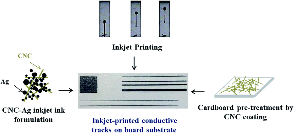 | ||
| Fig. 1 Schematic representation of the CNC–silver inkjet printing on CNC coated substrate. | ||
2. Experimental procedures
2.1 Materials
Polyethylene terephthalate sheets (Lyreco, ref – 182.406, 100 µm thickness), Powercoat® paper called PrintedElec paper (Arjowiggins, special printed electronic grade, 230 µm thickness) and a cardboard were used as printing substrate. 2,2,6,6-Tetramethylpiperidine 1-oxyl (TEMPO), sodium hypochlorite (12% wt), silver nitrate (AgNO3), hexadecylpyridinium chloride monohydrate (C21H38ClN·H2O), sodium borohydride (NaBH4) and dioctyl sodium sulfosuccinate salt (C20H37NaO7S) were purchased from Sigma-Aldrich and used as received. Sulfated cellulose nanocrystals were purchased from University of Maine as an hydrogel (7.26% wt). Distilled water was used in all experiments.2.2 TEMPO oxidation of CNC
TEMPO mediated oxidation of CNC was performed using a previously described procedure in the literature.31 11 g of CNC were dispersed by an ultrasonic probe treatment (5 min, 20 kHz) in 730 mL of water. TEMPO (325 mg, 2.08 mM) and NaBr (3.564 mg, 34.61 mM) were dissolved in 250 mL of deionized water and slowly added to the CNC suspension. A 12% wt NaClO suspension (66 g, 0.12 M) was then added dropwise to the suspension to start the oxidation. pH of the suspension was maintained around 10–10.5 by addition of 0.5 M NaOH solution while stirring the suspension for 3 h. Reaction was then quenched by the addition of ethanol (40 mL) and the resulting CNC were washed with hydrochloric acid 0.5 M at least three times by centrifugation (10![[thin space (1/6-em)]](https://www.rsc.org/images/entities/char_2009.gif) 000 rpm, 30 min). After three centrifugations, the CNC were re-dispersed using the minimum of distilled water needed to recover all the CNC and put in dialysis against distilled water until a neutral pH was obtained. TEMPO CNC were stored in the fridge at constant neutral pH to allow the CNC to be in their carboxylate form.
000 rpm, 30 min). After three centrifugations, the CNC were re-dispersed using the minimum of distilled water needed to recover all the CNC and put in dialysis against distilled water until a neutral pH was obtained. TEMPO CNC were stored in the fridge at constant neutral pH to allow the CNC to be in their carboxylate form.
2.3 Conductive ink formulation
Silver conductive ink suspension was synthetized following our previously described procedure.32 Produced oxidized CNC were used as both capping and stabilizing agent in the synthesis of silver nanoparticles: 200 mL of a 0.5% wt CNC suspension at neutral pH was mixed with 200 mL of a 0.5 mmol L−1 hexadecylpyridinium chloride solution during 5 minutes. 200 mL of AgNO3 (10 mmol L−1) was then added to the suspension and stirred during 5 additional minutes. Finally, 200 mL of a reducing agent solution (NaBH4/30 mmol L−1) was added and the suspension was stirred for another 5 minutes. The NaBH4 solution was freshly prepared prior each experiment. The resulting suspension was then centrifuged three times (10000 rpm, 20 minutes). The final sediment was re-dispersed in needed amount of deionized water by mechanical agitation followed by an ultra-sonic probe treatment (20 kHz, 3 × 15 min) to obtain a stable suspension.
2.4 Inkjet printing of CNC–silver system
A laboratory piezoelectric inkjet printing machine (Fujifilm – Dimatix DMP 2831 with 10 pL nominal drop size cartridge) was used to print the developed conductive suspension. This equipment allows the loading of disposable piezoelectric inkjet print heads including 16 nozzles of 21.5 µm (square shape) and distanced at 254 µm from each other. Prior to each experiment the inkjet print heads were degassed using a syringe and the purge system embedded on the printer. Printing parameters such as drop spacing, nozzle temperature and print height were set according to Table 1. Substrate temperature was set to 30 °C during the printing.| Drop spacing (µm) | Print height (mm) | Ink temperature (°C) |
|---|---|---|
| 15 | 1 | 28 |
Ejection parameters (voltage and waveform design) were optimized in preliminary adjustments. Cleaning cycles were performed every 50 printed bands to avoid temporary nozzle clogging and substrate contamination. Patterns including lines with variable widths (0.1 to 0.5 mm) and solid areas of 10 × 10 mm square were printed to evaluate the print quality and the electrical performances. After the printing, samples were allowed to dry at ambient air overnight. For conductivity measurement, annealing post-treatment (180 °C to 30 min) was performed in an oven to allow the sintering of silver nanoparticles. In addition, a drop watcher camera coupled with a drop volume measurement module was implemented to determine characteristics such as drop shape, drop velocity, and drop volume.
2.5 CNC coated substrate preparation
To meet the printed electronics requirements regarding substrate, a 10% wt CNC suspension was coated on the cardboard samples with a bar coater (Kcoater 301, Erichsen). To obtain a regular and thin film, a non wire-wound Mayer bar was used with a coating speed of 5.4 cm s−1. This configuration allows producing coating thickness of approximately 0.8 µm (SEM measurements). The coated cardboards were then dried under ambient air overnight.2.6 Suspension characterization
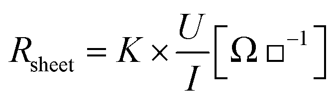
All the errors bars presented in the measurement represent the standard deviation of the measurement series.2.7 Substrate and printed patterns characterization
000, 50000 and 100000 were performed and at least 10 images per sample were recorded. A focus has been done to characterize the nanoparticles network (organization, distribution) within the printed layers. Thickness of the printed conductive films was also evaluated by analysing the cross sections at different locations using an EHT of 3 kV at magnifications of 8000 and 15000.
 | (1) |
To limit edge effects, measurements were performed on solid area patterns of 10 × 10 mm square. 10 measurements have been performed and the averaged value is presented.
3. Results & discussions
3.1 Conductive ink preparation and selection
TEMPO oxidized CNC are characterized by the presence of surface carboxylate groups.31 In this work, TEMPO CNC were used to act both as capping and stabilizing agent for silver nanoparticles synthesis.32 Indeed, in previous studies, we emphasize the importance of using oxidized CNC with a high surface charge density to enhance the silver synthesis on their surface and obtain a stable suspension.32 Moreover, the use of a cationic surfactant during the synthesis as well as the reactants ratios were identified as key factors to achieve stable silver aqueous suspensions with the highest silver loading.27 Considering the previous results, oxidized CNC with a high charge density of carboxylate moieties were used. The highly charged CNC ensure the suspension stability by the presence of repulsive interactions while allowing a better control of the silver synthesis.32 The charge density of our CNC was determined to be 1300 ± 51 µmol g−1 using conductimetric titration.31 The CNC dimensions were measured to be 200 ± 19 nm in length and 20 ± 2 nm in diameter using AFM. These CNC nanometrical dimensions are essential given the inkjet particle size limitation (<1 µm to avoid nozzles clogging).Synthesis of the silver nanoparticles on CNC was done according to a previously presented protocol.27 An optimal CNC to silver ratio was used to control the silver nanoparticles synthesis based on preliminary experiments (not presented here). With the aim of achieving stable conductive suspension, impact of silver amount in the suspension was first evaluated on the suspension stability and conductivity. Suspensions electrical properties were estimated by a drop casting technique.33 A 5 µL drop was deposited on a printed electronic paper followed by a sintering at 180 °C during 30 min (10 measurements for each suspension). This preliminary approach was performed in order to select conductive suspensions. Table 2 summarizes the characteristics of each prepared suspension.
| CNC content (% wt) | Silver content (% wt) | 5 µL drop resistance (Ω) | Sedimentation time (days) | |
|---|---|---|---|---|
| CNC–silver1 | 0.4 ± 0.4 | 1.0 ± 0.1 | Not conductive | Stable |
| CNC–silver2 | 0.9 ± 0.3 | 2.1 ± 0.1 | Not conductive | Stable |
| CNC–silver3 | 1.2 ± 0.4 | 2.9 ± 0.2 | 0.31 ± 0.01 | Stable |
| CNC–silver4 | 2.1 ± 0.1 | 4.2 ± 0.2 | 0.12 ± 0.02 | 1 day (unstable) |
Surprisingly, the suspension starts to be conductive at a silver content around 3% wt Considering that the percolation rate of conventional silver nanoparticle suspensions is around 20% wt, we believe that, in our case, a percolated network was achieved at a lower silver content due to changes in the network organization happening with the CNC. When increasing the silver amount above 3 wt%, the suspension became unstable with visible silver particles sedimentation occurring after only 1 day. This loss in suspension stability can be explained by changes in electrostatic interactions between the CNC–silver particles. As the CNC–silver content in the suspension is increased, the distance between each CNC–silver particle is decreased due to a decrease in available spatial volume. This change in inter-particles distance leads to changes in their interactions. Starting a given concentration of silver, the attractive silver–silver interactions then became dominant over the CNC anionic repulsive forces, therefore inducing the particles aggregation and sedimentation.
The 3% wt silver suspension was thus selected for evaluating the suitability of the suspension to be processed by inkjet printing. The synthetized silver particles dimensions within this suspension was estimated to 64 ± 16 nm, which should be in accordance, as for CNC particles, with the size limitation imposed by the inkjet printing process.
3.2 Optimization of CNC–silver suspension for inkjet process
Physico-chemical properties of the selected CNC–silver hybrid formulation, namely rheological behavior and surface tension, were first evaluated to determine the suitability of the suspension regarding inkjet printing process. The rheological behavior of the CNC–silver suspension (not presented here) shows a shear thinning behavior against the whole range of shear rate. Besides the shear thinning behavior, the viscosity of the suspension at 1000 s−1 was estimated to 1.2 mPa s, which is in accordance with the low-viscosity window targeted for the inkjet printing process.The suitability of the suspension for inkjet printing was evaluated by the mean of a dimensionless number analysis. Indeed, in piezoelectric inkjet printing process, the ink droplet is ejected thanks to an electromechanically impulsion induced by a piezoelectric element. The droplet is jetted only if its kinetic energy overcomes interactions linked to surface energy and viscous forces. Both conditions are formulated through the dimensionless numbers Weber 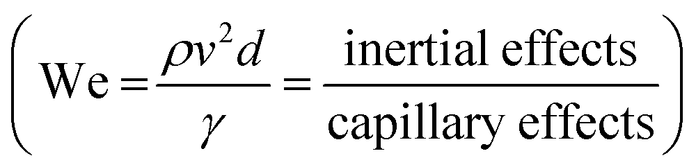 and Reynolds
 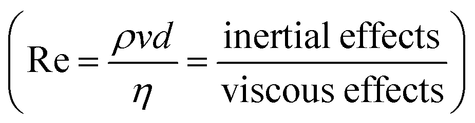 , which must be superior to 1 for ensuing droplet ejection. We number describes the kinetic-surface energy conversion governed by the speed of the jet and the surface tension. Re number takes into account the viscosity effects. An approach combining these two dimensionless numbers for predicting a fluid inkjettability was firstly proposed by Fromm et al. and was refined later by Derby et al.34,35 In these studies, the fluid properties are described by the Z number, which is the inverse of Ohnesorge number (Oh). Oh characterizes the propagation of the pressure wave and its attenuation by viscous dissipation. The Z number is then defined as below in eqn (2).
 | (2) |
Fromm et al. have predicted that a suspension can be ejected by inkjet nozzle only if Z > 2. Following this work Derby and Reis specified that a stable droplet formation is obtained for 1 ≤ Z ≥ 10. Finally, Jang et al. redefined then the printable range as 4 ≤ Z ≥ 14 considering additional parameters like droplet generation and positional accuracy.36 Printing using a fluid with Z < 4 will lead to a drop formation with undesired long-lived filament while inks with Z > 14 would not be able to form a single droplet without undesired satellites drops.
Table 3 (first line) summarized the suspension properties and associated dimensionless number. Calculations were made considering a nozzle diameter of 21.5 µm and a suspension density of 996 kg m3. As it can be seen, the Z number calculated for the CNC–silver suspension (Z = 20) appears too high to allow a correct ejection of the ink. Considering the high surface tension of 50.1 mN m−1 of the ink, formulation adjustments were performed to lower this value by adding different amount of dioctyl sulfosuccinate (DSS) surfactant. Table 3 summarized the characteristics of the different suspension prepared with the associated evolution of the surface tension and Z number. As expected, the surfactant addition leads to a decrease in surface tension and an acceptable value of Z (Z = 13.3) was reached for a minimum concentration in surfactant of 0.15% wt, which corresponds to a surface tension of 29.1 mN m−1. As surfactant molecules are known for being insulative and can thus affect the conductivity of our system, the lowest surfactant concentration required to meet inkjet requirements (0.15% wt) was selected for the next results.
| Suspension | DSS surfactant amount (wt%) | η – 1000 s−1 (mPa s) | σ (mN m−1) | Droplet speed (m s) | Re | We | Z |
|---|---|---|---|---|---|---|---|
| CNC–silver | 0 | 1.2 ± 0.3 | 50.1 ± 0.7 | 15 | 43 | 133 | 20.4 |
| DSS (0.05) | 0.05 | 1.3 ± 0.2 | 41.3 ± 0.9 | 14 | 52 | 142 | 19.7 |
| DSS (0.15) | 0.15 | 1.9 ± 0.4 | 29.1 ± 0.1 | 14 | 71 | 101 | 13.3 |
| DSS (0.2) | 0.2 | 1.9 ± 0.3 | 26.7 ± 0.3 | 14 | 80 | 112 | 12.5 |
Inkjet printing of the selected suspension was then evaluated. No nozzles clogging and with a stable droplet formation have been observed during the printing. This printing stability is in good agreement with the previous theoretical expectations. It is worth mentioning that even after 1 month, no additional clogging was observed with the same print head, confirming the high stability of the ink.
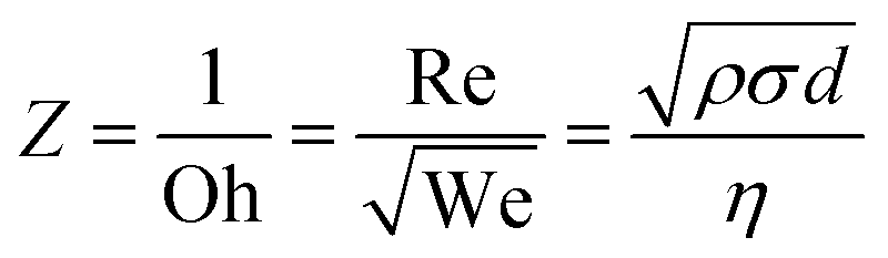
Optimization of inkjet printing parameters was done to obtain the most spherical drops. The firing voltage was thus set to 30 V with an associated waveform presented in Fig. 2a.
 | ||
| Fig. 2 (a) Inkjet waveform; (b) photograph of CNC–silver fired drops and (c) optical microscope image of inkjet printed droplets. | ||
Resulting drops in Fig. 2b shows that single spherical droplets with a small tail are fired, in good agreement with the previously calculated Z number of 13.3. The microscope image in Fig. 2c shows that the preliminary printed drops on printed electronics paper possess a spherical shape with no satellite drops around the printing. These results suggest that the selected suspension was indeed suitable to provide inkjet printed tracks.
Advantage of the suspension especially lies on the use of CNC shape for obtaining a conductive inkjet ink at low solid content due to the use of CNC and their percolation ability.
Classical silver inks are usually conductive with 20% wt of silver in the suspension. Thus, by using the CNC–silver suspension, the cost in silver material is decreased with only 3% of silver used. Another advantage lie on the aqueous stability, which is very difficult to obtain with silver nanoparticles. Thank to the use of CNC, the suspension can be stable in water.
3.3 Influence of substrate properties on CNC–silver ink printability
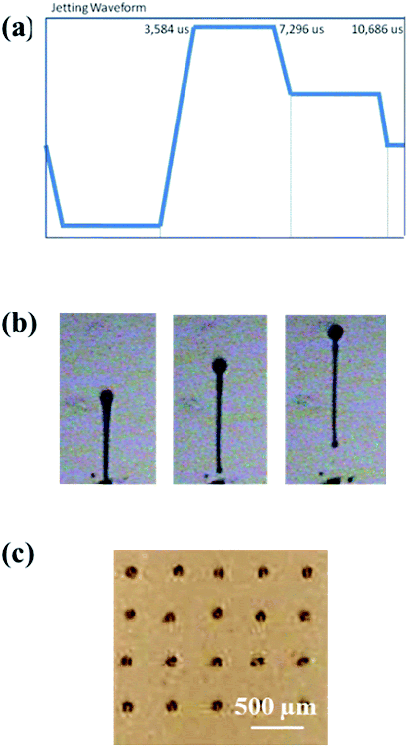
The optimized selected CNC–silver suspension was printed onto classical printed electronics substrates, namely PET plastic foil and printed electronic Powercoat® paper (PrintElec paper). A neat porous cardboard was also evaluated as a cellulosic reference substrate for conductive printing. To prepare the cardboard surface, a CNC coating was tried out to meet the printed electronic requirements. Indeed, it has been shown that nanocellulose films can provide green and renewable substrates suitable for the printing of conductive tracks.23,24 However, no work has evaluated the impact of a nanocellulose coating on classical cellulosic substrates. Thus, with the aim of (i) studying the influence of a CNC coating on the printability of our ink and (ii) evaluating the suitability of such coating for the printing of conductive tracks, a CNC suspension was coated on the porous cardboard substrate. The obtained properties were compared to that of the neat paperboard substrate and the classical printed electronics substrates.The different substrates properties, summarized in Table 4, shows that the selected CNC–silver ink should theoretically have appropriate interactions with all substrates. Indeed, as the surface tension of the suspension is inferior to the surface energy of each substrate, a good wetting of the substrate by the ink should be observed. The printing quality achieved on each substrate was analyzed using optical microscope imaging. Observations were made on both individual printed drops and 200 µm printed lines. Observations of printed lines in Fig. 3 show an inhomogeneous printing on PET and PrintElec paper with an unequal ink repartition along the line, which is also evidenced on the printed solid areas (not presented here).
| Substrate | Surface energy (mN m−1) | Ra roughness (nm) |
|---|---|---|
| PET | 41 ± 1 | 5.3 ± 0.5 |
| Printed Elec paper | 32 ± 4 | 10.1 ± 7.4 |
| Board | 36 ± 5 | 66.2 ± 8.1 |
| Board + CNC | 49 ± 4 | 3.6 ± 1.2 |
 | ||
| Fig. 3 Optical microscope images of a 200 µm printed line of CNC–silver suspension on (a) printed electronic paper; (b) PET; (c) neat board and (d) CNC coated board substrate. | ||
A coffee ring effect is visible on both substrates with higher material amount on the edge of the printed patterns. This is also confirmed by the inset images in Fig. 3, showing the individual printed drop on the different substrates. The coffee ring effect is clearly evidenced with a material reorganization towards the edge of the pattern. The coffee ring effect is a well-known studied printing defect (first described by Deegan et al., 1997), especially occurring with the inkjet printing process due to the low viscosity of the fluid. This phenomenon is induced during the droplet drying phase37 by the combination of two actions: (i) the solvent evaporation is more important at the edge of drops and (ii) the surface contact area between ink and substrate is pinned for the major part of the drying. A flow takes place to compensate the solvent removal by evaporation at the edge of droplet. The solvent, and subsequently the suspended particles, can then be totally or partially transferred to the contact line by this flow and generate a ring shape to the dried droplet. Additional unequal ink repartition is visible on both PET and powercoat® printed lines and might be due to a liquid film reorganization happening during the printing. This phenomenon was already described as bulging defect by Duineveld38 and later Soltman39 who suggested that when the contact angle – due to additional fluid from printing – is higher to that of equilibrium contact angle, a liquid reorganization within the printed film happened despite a theoretical ink-substrate compatibility.38 Thus, we believe that our ink is leading to both of these defects on both PET and PE paper, especially due to the fact that it is water-based. Indeed, several studies demonstrated that water-based ink favors the coffee ring due to a non-uniform evaporation of the volatile water as compared to solvent based suspension.40 This phenomenon is usually compensate by adding a less volatile co-solvent within the ink formulation.41 However, in our case, this solution has not been considered for developing a 100% aqueous based ink.
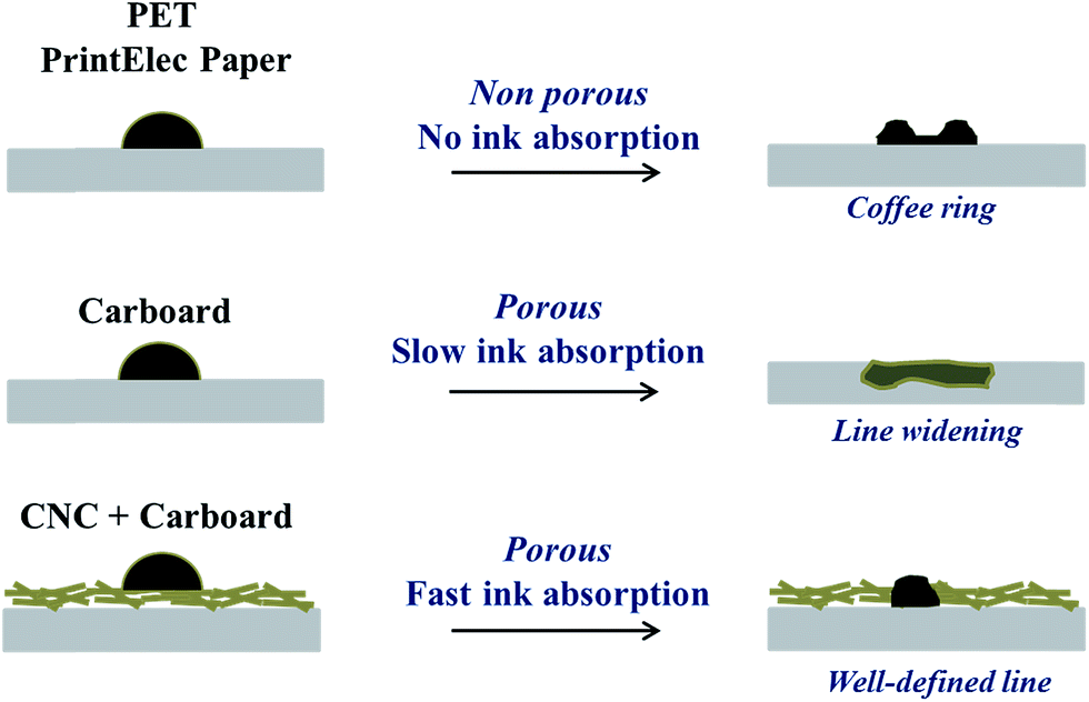
The printing on neat cardboard evidenced classical printing defects on porous substrate, with visible ink infiltration and spreading onto the substrate. The ink infiltration into the substrate leads to high line widening of 75%. Interestingly, when printing on the CNC coated cardboard substrate a well-defined line was obtained with a smaller line widening of 24% as compared to neat board. These results are in accordance with a recent patent who described an increased printability for a CNC coated plastic substrate.29
Comparison of the printing on different substrates evidenced a better printing quality on the CNC coated cardboard. This higher printing quality obtained on the CNC coated substrate can originate from different parameters such as differences in substrate roughness, porosity (or capillary absorption) or surface energy. Previously introduced Table 4, comparing the roughness of the different substrates, shows that the roughness of the cardboard is divided by almost 20 when using a CNC coating. These results, demonstrating the effectiveness of a CNC coating to lower a substrate roughness, can explain the more homogeneous material deposition. However, the roughness of the coating remains higher to that of classical printed electronics substrates. The inset images of the printed drop on the CNC coating show more irregular shape than the spherical ones obtained on PET and PrintElec paper, probably due to this higher roughness. Consequently, considering the more regular shapes on PET and PrintElec, the roughness alone does not explain the better line definition obtained on the CNC coating.
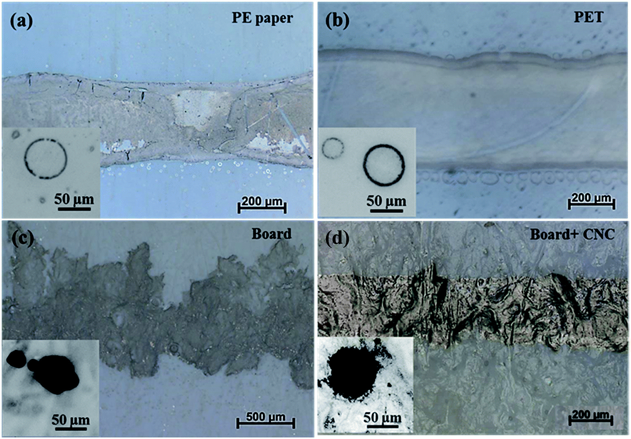
Some studies have demonstrated the importance of ink penetration for the printing of conductive tracks on paper.42,43 In our case, we believe that the use of a CNC coating would modify the ink penetration inside the substrate. Indeed, the very dense and close nanometrical network formed by the CNC coating probably impacts the substrate liquid absorption surface properties, thus explaining the better print quality on the treated cardboard substrate. To confirm this hypothesis, drop volume time-dependent measurements were performed on both neat and CNC coated cardboard to evaluate the ink absorption kinetic. Considering that evaporation rate of inkjet-printed drops occurs fastly for water-based suspensions (∼800 ms),44 measurements were done on a short time period. Fig. 4 presents the drop volume evolution against time of the CNC–silver ink on neat cardboard and CNC coated board substrate.
 | ||
| Fig. 4 Drop volume evolution of the CNC–silver ink on the CNC coated board and neat board using contact angle experiment. | ||
When deposited on the CNC coated substrate, the volume of the drop shows an immediate decrease (see the inset of the figure) before reaching a stable value after only ≈0.2 seconds. On the contrary, when deposited on neat cardboard the ink drop volume shows a slow decrease up to 30 s, due to the diffusion of the ink inside the substrate. This result, representative of a faster ink absorption by the CNC coated cardboard as compared to the long and continuous absorption of the neat cardboard, can explain the different print quality obtained on the two substrates. Indeed, absorption kinetics presented in Fig. 4 clearly evidenced that the CNC coating increase the ink absorption speed by the substrate, probably due to the high surface area of the nanoscale CNC compared to neat cellulose fiber of the cardboard. Over a period of 800 ms, the average absorption speed for the CNC coating has been calculated to be 1.5 µL s−1 against only 0.5 µL s−1 for the neat cardboard. Consequently, when a printed drop reach the CNC coated substrate, absorption of the drop happens so fast that the printed drop would not have time to diffuse inside the substrate. It worth mentioning that drop volumes in inkjet printing are much lower (∼pL) than the one studied, suggesting that these effects happened even faster during the printing of the CNC–silver suspension.
Additionally, this faster absorption kinetic might also explain the absence of coffee ring on the CNC coating as compared to PET or PrinElec paper substrate. Indeed, volume of drops fired by inkjet can be considered to be around 2 to 70 pL.44,45 Using the previously calculated average speed, the maximal drop volume of 70 pL would be absorbed in about 46 ms by the CNC coating whereas the evaporation time of an aqueous inkjet drop was estimated to be around 800 ms.44 Thus, the flux at the origin of the coffee ring effect, which happens during the evaporation stage of the drop, would not have time to occur. This hypothesis, schematically illustrated in Fig. 5, also explains the higher printing quality and definition obtained on the CNC coated substrate.
 | ||
| Fig. 5 Schematic illustrations of the mechanisms happening after drop impact on the different substrates. | ||
The previous results evidenced that the best printing quality was obtained on the cardboard coated CNC substrate with a good line resolution and limited ink infiltration. This 100% cellulosic substrate can provide a green solution for the printing of conductive tracks with the advantage of possessing a higher thermal stability than plastic based substrate. As compared to a 100% nanocellulosic substrate, the coating solution provides an easy way for tuning substrate properties using a low amount of nanocellulosic material.
3.4 CNC–silver ink electrical properties
According to the previous results, the best print quality was obtained on the CNC coated paperboard substrate. Electrical properties of the ink were then evaluated using this substrate. It is well known that silver nanoparticles network became conductive after an annealing treatment needed for forming a continuous silver network. Fig. 6 represents the evolution of the sheet resistance according to the temperature and associated network evolution.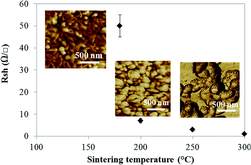 | ||
| Fig. 6 Evolution of the sheet resistance against the sintering temperature and associated with AFM images of the network. | ||
As it can be seen, at intermediate annealing temperature (30 min to 180 °C), the obtained sheet resistance of about 50 Ω □−1 appears quite high as compared to obtained performances of classical silver nanoparticle inks reported in the literature.46 However, considering the silver content of 3% wt in the suspension, it is not surprising that conductivity is lower to that of classical silver inks containing at least 20% wt of silver.47 In addition, the presence of insulative surfactant and nanocellulose around the silver particles visible in both AFM image of the network in Fig. 6 suggests that the CNC presence limits the network conductivity, leading to a degraded sheet resistance value. This was confirmed by the evolution of the sheet resistance happening when increasing the annealing temperature around the cellulose degradation temperature (250 °C). The sheet resistance dramatically decreases from 50 Ω □−1 and to 1 Ω □−1 with a clear loss of the visible CNC on AFM images. Thus, although CNC ensure the stability of the silver suspension, the insulative nature of CNC appears as a limitation to achieve high conductive patterns at low sintering temperature. However, it is important to highlight that despite the very low silver content loaded in the suspension, an interesting level of electrical conductivity was achieved with sufficient annealing treatment. This is probably due to the use of CNC, which allows a significant decrease of the silver particles percolation threshold. Indeed, the high aspect ratio of CNC acts as a scaffold for silver nanoparticles allowing a network organization, resulting in a decrease of the network percolation threshold. SEM images in Fig. 7 confirm this hypothesis with visible silver particles (black dotted arrows) onto the CNC (white arrows) and no free silver particles.
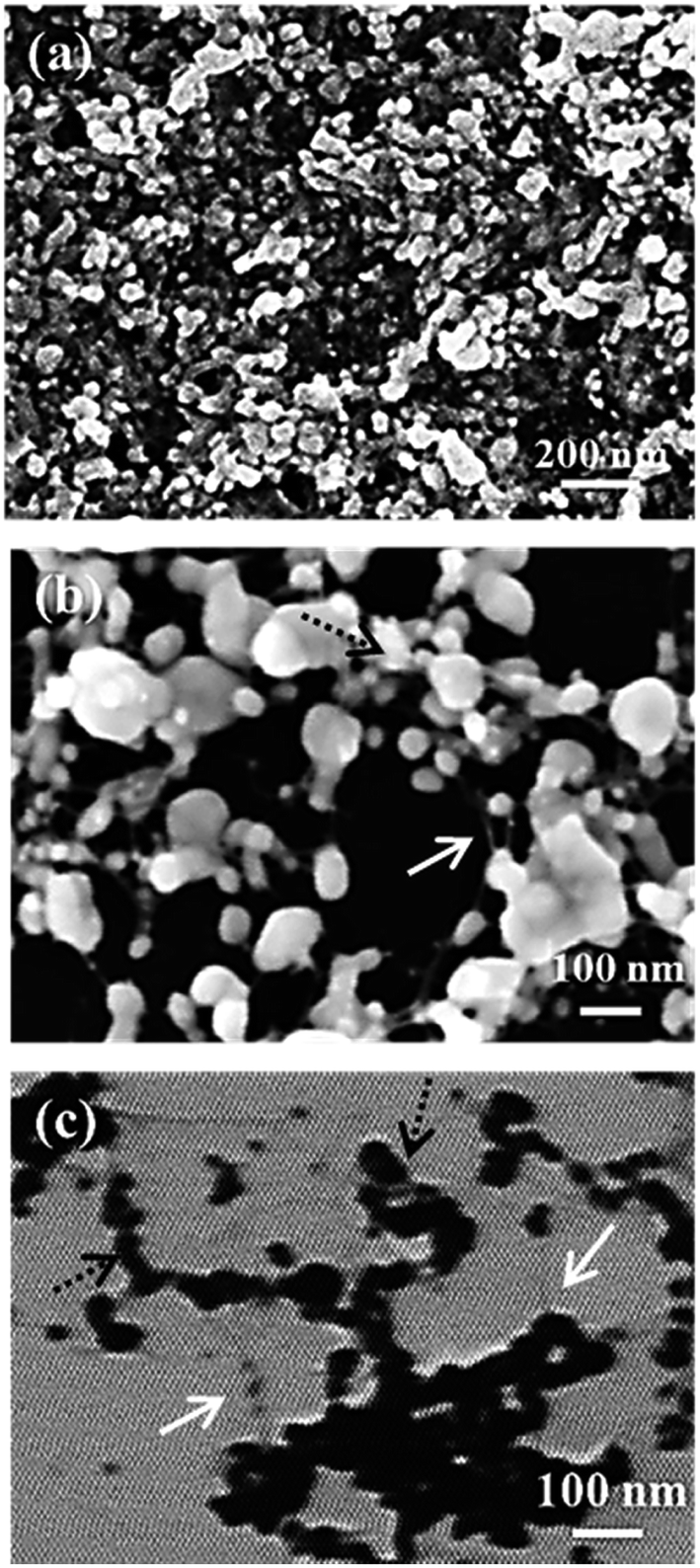 | ||
| Fig. 7 SEM images of the CNC–silver ink after sintering at 180 °C to 30 min for (a) the dried CNC–silver printed film, (b) the diluted CNC–silver ink and (c) STEM image of the same diluted and sintered CNC–silver ink. | ||
This decrease in the percolation threshold when using CNC has already been reported for conductive polymers composite films48,49 but, as far as we know, this is the first time that it has been reported for conductive silver particles. Considering these results, we believe that both the insulative cellulose and the silver solid content in the suspension limits the suspension conductivity. However, the use of CNC as a template for conductive silver material offers a green alternative for producing stable, cost-competitive and low-solid content conductive suspension. Optimization of the conductivity level can further be achieved by: (i) increase the silver loading in the suspension or (ii) eliminate the insulative cellulose after the synthesis. Preliminary trials were done by addition of sulfuric acid within the suspension to favor cellulose removal during the sintering step. However, up to now, acid addition leads to a loss of suspension stability and further works should then be done towards this way.
4. Conclusion
The present work evaluates the possibility of using CNC to enhance both ink and substrate properties for printed electronics applications. The nanometrical size of CNC and their dispersing properties allow producing a compatible conductive silver inkjet ink. SEM images of the hybrid system evidence the presence of silver nanoparticles onto the CNC acting as a scaffold for the conductive material. A conductive ink at a low silver solid content was then achieved thanks to the CNC high aspect ratio and colloidal stability. Table 5 emphasizes the positioning of the developed ink towards inkjet silver conductive ink conventional properties.| Conventional ink47 | Our work | |
|---|---|---|
| Silver content (%) | ≈20% | ≈3% |
| Rsh (Ω □−1) | 0.1–0.5 | 1–50 |
| Minimal line width (µm) | 50 µm | 100 µm |
| Sintering conditions | 110–200 °C | 180–250 °C |
Impact of CNC coating on the print quality was also investigated. This easy substrate pre-treatment leads to decrease the substrate roughness but also strongly increase the ink absorption kinetic of low volume. This faster absorption significantly limits the ink drop (picoliter) diffusion into a porous substrate, providing suitable properties for conductive tracks printing. The printing of the CNC–silver ink on such substrate allow producing conductive tracks with high resolution. However, it appears that the remaining CNC into the printed tracks limits the inks conductivity. Further works should then be focused on optimizing the obtained conductivity by either synthetizing conductive CNC prior the silver synthesis, eliminating the cellulose during or after the printing or trying others sintering strategies such as infrared or flash sintering on the printed film. Nevertheless, this innovative work provides a new solution to obtain conductive patterns on a porous substrate, with very low silver content within the dried film. The use of CNC as scaffold offers green way to produce a low-solid content conductive suspension. The produced conductive patterns on the CNC coating are then almost only composed of cellulosic material, thus offering a path towards renewable and sustainable electronics.
Acknowledgements
Authors acknowledge the French National Research Agency (ANRT) and Poly-Ink for the financial and material support of the PhD thesis. LGP2 is part of the LabEx Tec 21 (Investissements d'Avenir – grant agreement no. ANR-11-LABX-0030) and of the Energies du Futur and PolyNat Carnot Institutes. This research was made possible thanks to the facilities of the TekLiCell platform funded by the Région Rhône-Alpes (ERDF: European regional development fund). Authors also acknowledge Orlando Rojas for its advices towards a complementary study.References
- A. Rida, R. Vyas and M. M. Tentzeris, IEEE Antenn. Propag. Mag., 2009, 51, 13–23 CrossRef.
- M. Mäntysalo and P. Mansikkamäki, AEU - Int. J. Electron. Commun., 2009, 63, 31–35 CrossRef.
- E. Sowade, K. Y. Mitra, E. Ramon, C. Martinez-Domingo, F. Villani, F. Loffredo, H. L. Gomes and R. R. Baumann, Org. Electron., 2016, 30, 237–246 CrossRef CAS.
- H. Yan, Z. Chen, Y. Zheng, C. Newman, J. R. Quinn, F. Dötz, M. Kastler and A. Facchetti, Nature, 2009, 457, 679–686 CrossRef CAS PubMed.
- W. Cao, J. Li, H. Chen and J. Xue, J. Photonics Energy, 2014, 4, 040990 CrossRef.
- F.-G. Zeng, C.-C. Zhu, W. Liu and X. Liu, Microelectron. J., 2006, 37, 495–499 CrossRef CAS.
- T. Furukawa, N. Kawamura, J. Inoue, H. Nakada and M. Koden, Dig. Tech. Pap. - Soc. Inf. Disp. Int. Symp., 2015, 46, 1355–1358 CrossRef CAS.
- F. C. Krebs, M. Jørgensen, K. Norrman, O. Hagemann, J. Alstrup, T. D. Nielsen, J. Fyenbo, K. Larsen and J. Kristensen, Sol. Energy Mater. Sol. Cells, 2009, 93, 422–441 CrossRef CAS.
- D. Raghu and H. Peter, Printed, Organic & Flexible Electronics Forecasts, Players & Opportunities 2015-2025: IDTechEx, 2015 Search PubMed.
- B. Y. Tay and M. J. Edirisinghe, J. Mater. Sci., 2012, 37, 4653–4661 CrossRef.
- F. Hoeng, A. Denneulin and J. Bras, Nanoscale, 2016, 8, 13131–13154 RSC.
- J. Bras, D. Viet, C. Bruzzese and A. Dufresne, Carbohydr. Polym., 2011, 84, 211–215 CrossRef CAS.
- V. Kumar, R. Bollström, A. Yang, Q. Chen, G. Chen, P. Salminen, D. Bousfield and M. Toivakka, Cellulose, 2014, 21, 3443–3456 CrossRef CAS.
- K. Torvinen, J. Sievänen, T. Hjelt and E. Hellén, Cellulose, 2012, 19, 821–829 CrossRef CAS.
- Y. Fujisaki, H. Koga, Y. Nakajima, M. Nakata, H. Tsuji, T. Yamamoto, T. Kurita, M. Nogi and N. Shimidzu, Adv. Funct. Mater., 2014, 24, 1657–1663 CrossRef CAS.
- S. Ifuku, M. Tsuji, M. Morimoto, H. Saimoto and H. Yano, Biomacromolecules, 2009, 10, 2714–2717 CrossRef CAS PubMed.
- M. Wu, S. Kuga and Y. Huang, Langmuir, 2008, 24, 10494–10497 CrossRef CAS PubMed.
- W. G. Reed and J. O. Renn, US Pat., US2011026264, 2011.
- O. Pras, D. Beneventi, D. Chaussy, P. Piette and S. Tapin-Lingua, J. Mater. Sci., 2013, 48, 6911–6920 CrossRef CAS.
- Z. Shi, J. Tang, L. Chen, C. Yan, S. Tanvir, W. A. Anderson, R. M. Berry and K. C. Tam, J. Mater. Chem. B, 2014, 603–611 Search PubMed.
- N. Drogat, R. Granet, V. Sol, A. Memmi, N. Saad, C. Klein Koerkamp, P. Bressollier and P. Krausz, J. Nanopart. Res., 2010, 13, 1557–1562 CrossRef.
- R. Xiong, C. Lu, W. Zhang, Z. Zhou and X. Zhang, Carbohydr. Polym., 2013, 95, 214–219 CrossRef CAS PubMed.
- G. Chinga-Carrasco, D. Tobjörk and R. Österbacka, J. Nanopart. Res., 2012, 14, 1213 CrossRef.
- M.-C. Hsieh, C. Kim, M. Nogi and K. Suganuma, Nanoscale, 2013, 5, 9289–9295 RSC.
- M. Nogi, N. Komoda, K. Otsuka and K. Suganuma, Nanoscale, 2013, 5, 4395–4399 RSC.
- H. Koga, T. Saito, T. Kitaoka, M. Nogi, K. Suganuma and A. Isogai, Biomacromolecules, 2013, 14, 1160–1165 CrossRef CAS PubMed.
- F. Hoeng, A. Denneulin and J. Bras, Positive Impact of Cellulose Nanofibrils on Silver Nanowires Coatings for Transparent Conductive Films, Printed electronic conference, Santa Clara, 18–19 Nov 2015 Search PubMed.
- F. Navarro, M. Roman, A. R. Esker, R. M. Davis and S. H. Renneckar, Cellulose Nanocrystals: Size Characterization and Controlled Deposition by Inkjet Printing, ACS spring, San Francisco, 22–25 March 2010 Search PubMed.
- W. G. Reed and J. O. Renn, Electrically isolated heat sink for solid-state light, US20110026264 A1, 2011.
- L. Zhang, E. G. Burns, T. Liu and J. A. Bates, Aqueous Dispersions Comprising Nanocrystalline Cellulose, and Compositions for Commercial Inkjet Printing, US2014267515, 2014.
- Y. Habibi, H. Chanzy and M. R. Vignon, Cellulose, 2006, 13, 679–687 CrossRef CAS.
- F. Hoeng, A. Denneulin, C. Neuman and J. Bras, J. Nanopart. Res., 2015, 17, 244 CrossRef.
- M. Binda, in Organic Electronics: principles, devices and applications, November 26–29th, 2013 Search PubMed.
- J. E. Fromm, IBM J. Res. Dev., 1984, 28, 322–333 CrossRef.
- N. Reis and B. Derby, MRS Online Proc. Libr., 2011, 625, 117 CrossRef.
- D. Jang, D. Kim and J. Moon, Langmuir, 2009, 25, 2629–2635 CrossRef CAS PubMed.
- R. D. Deegan, O. Bakajin, T. F. Dupont, G. Huber, S. R. Nagel and T. A. Witten, Nature, 1997, 389(6653), 827–829 CrossRef CAS.
- P. C. Duineveld, J. Fluid Mech., 2003, 477, 175–200 Search PubMed.
- D. Soltman and V. Subramanian, Langmuir, 2008, 24, 2224–2231 CrossRef CAS PubMed.
- H. Hu and R. G. Larson, J. Phys. Chem. B, 2006, 110, 7090–7094 CrossRef CAS PubMed.
- J.-L. Lin, Z.-K. Kao and Y.-C. Liao, Langmuir, 2013, 29, 11330–11336 CrossRef CAS PubMed.
- E. Hrehorova, A. Pekarovicova, V. N. Bliznyuk and P. D. Fleming, Polymeric Materials for Printed Electronics and Their Interactions with Paper Substrates, in NIP & Digital Fabrication Conference, Society for Imaging Science and Technology, 2007, pp. 928–931 Search PubMed.
- P. Antti, S. Jenni, T. Katariina, O. Kimmo and J. A. Ketoja, Cellulose, 2013, 1413–1424 Search PubMed.
- T. Lim, S. Han, J. Chung, J. T. Chung, S. Ko and C. P. Grigoropoulos, Int. J. Heat Mass Transfer, 2009, 52, 431–441 CrossRef CAS.
- A. Denneulin, J. Bras, A. Blayo, B. Khelifi, F. Roussel-Dherbey and C. Neuman, Nanotechnology, 2009, 20, 385701 CrossRef PubMed.
- J. Ran, L. X. Mo, W. B. Li, W. W. Li, X. M. Fan, J. L. Fu and L. H. Li, Appl. Mech. Mater., 2012, 262, 501–504 CrossRef.
- A. Kamyshny, J. Steinke and S. Magdassi, Open Appl. Phys. J., 2011, 19–36 CrossRef CAS.
- E. Tkalya, M. Ghislandi, W. Thielemans, P. van der Schoot, G. de With and C. Koning, ACS Macro Lett., 2013, 2, 157–163 CrossRef CAS.
- O. van den Berg, M. Schroeter, J. R. Capadona and C. Weder, J. Mater. Chem., 2007, 17, 2746 RSC.
| This journal is © The Royal Society of Chemistry 2017 |