
 Open Access Article
 This Open Access Article is licensed under a
 Creative Commons Attribution 3.0 Unported Licence
Development and characterization of heparin-immobilized polycaprolactone nanofibrous scaffolds for tissue engineering using gamma-irradiation
Jin-Oh Jeong†
ac,
Sung In Jeong†a,
Jong-Seok Parka,
Hui-Jeong Gwona,
Sung-Jun Ahna,
Heungsoo Shinb,
Jae Young Lee c and
Youn-Mook Lim*a
c and
Youn-Mook Lim*a
aResearch Division for Industry & Environment, Advanced Radiation Technology Institute, Korea Atomic Energy Research Institute (KAERI), 29 Gumgugil, Jeongeup, 56212, Republic of Korea. E-mail: ymlim71@kaeri.re.kr; Tel: +82-63-570-3065
bDepartment of Bioengineering, Division of Applied Chemical and Bio Engineering, Hanyang University, Seoul 133-791, Republic of Korea
cSchool of Materials Science and Engineering, Gwangju Institute of Science and Technology (GIST), Gwangju 61005, Republic of Korea
First published on 30th January 2017
Abstract
Polycaprolactone (PCL) has been considered a useful material for orthopedic devices and osseous implants because of its biocompatibility and bone-forming activity. However, PCL-based scaffolds have hydrophobic surfaces that reduce initial cell viability. In this study, we fabricated surface-modified PCL nanofibers for tissue engineering using radiation technology. We supplemented the hydrophilicity of the PCL nanofibers by introducing 2-aminoethyl methacrylate (AEMA) through gamma-irradiation and subsequently immobilized heparin onto the nanofibers using the EDC/NHS reaction. The SEM images show that there is almost no change in the morphology of nanofibers after radiation grafting of AEMA and heparin-immobilization onto PCL nanofibers. The surface properties of the scaffolds were characterized by ATR-FTIR, XPS, and fluorescamine staining in order to confirm the successful grafting of AEMA onto the PCL nanofibers. Immobilization of heparin was also confirmed by the amide I (1650 cm−1) and amide II group (1550 cm−1) from ATR-FTIR. The amounts of heparin were drastically increased on the AEMA–PCL nanofibers as revealed by TBO assay. The initial cell viability of hMSCs was significantly increased on the AEMA grafted nanofibers but grew slowly on heparin-immobilized nanofibers. The cumulative release of bone morphogenetic protein-2 (BMP-2) was slow and continuous onto the heparin-immobilized nanofibers (18.13 ± 3.87 μg mL−1) compared to PCL nanofibers (20.25 ± 1.45 μg mL−1). Therefore, heparin-immobilized nanofibers may be a good tool for tissue engineering applications using radiation technology.
1. Introduction
For successful engineering of damaged tissues or organs, such as bone, blood vessels, and skin, the appropriate cells, growth factors, and synthetic or naturally derived scaffolds should be combined.Recently, more focus has been given to studying bone repair due to an aging population and an increase in social activities that lead to frequent accidents. For example, damage caused by bone fractures and ligament ruptures results in increased pain in elderly individuals who have serious health problems, such as osteoporosis. Teams of tissue engineers have been actively developing three-dimensional (3D), highly porous structures to act as bioactive scaffolds for bone tissue engineering that can promote new tissue growth by assisting and speeding up the healing process.1,2 An ideal artificial scaffold should be designed to mimic the native extracellular matrix (ECM) structure as much as possible. Scaffolds for bone regeneration need to be three-dimensional and highly porous to support uniform cell attachment and proliferation, and also need to have an interconnected and permeable pore network to promote nutrient and waste exchange. Many methods to prepare porous three-dimensional biodegradable scaffolds have been developed in bone tissue engineering, including gas forming, salt leaching/particulate leaching, overrun process, phase separation, and electrospinning.3–7
Electrospinning is an efficient way of producing nanofibrous structures for natural and synthetic polymers. Large pore size, thickness, and a tunable surface area to volume ratio of electrospun scaffolds are important features of tissue-engineered scaffolds that strongly enhance cellular adhesion, proliferation, and infiltration.8,9 Typical biocompatible synthetic polymers such as poly (L-lactic acid) (PLLA), poly (glycolic acid) (PGA), poly (lactic-co-glycolic acid) (PLGA), and polycaprolactone (PCL) have been electrospun for bone tissue engineering.10–12
Among the synthetic biopolymers, the FDA-approved PCL has a good mechanical strength, unique elasticity, and hardness similar to that of bone, and it degrades faster than either homopolymer. Biodegradable synthetic polymer scaffolds from electrospun PLLA nanofibers, PLGA/hydroxyapatite composites, and HA–titanium have been used for the controlled, sustained, and localized release of BMP-2.13–15
Bone morphogenetic protein-2 (BMP-2) is known to increase bone formation significantly and to improve the adhesion, proliferation, differentiation and mineralization of osteoblasts when incorporated within the scaffold. The advantages of using BMP-2 have also been demonstrated on nanofibrous scaffolds for bone tissue engineering. However, the release of BMP-2 was uncontrolled due to a rapid release and a short half-life of activity. To overcome these weakness, the use of heparin in creating heparin-immobilized titanium surfaces and heparin-conjugated PLGA scaffolds has been studied.16,17
Heparin is a sulfated glycosaminoglycan (GAG), and it has a variety of biological activities, such as the ability to induce diverse changes in the chemical structure and structural specificity of anionic functional groups. The biological activity of heparin is associated with the interaction and binding affinity to different proteins.18 However, when introducing additional heparin, the existing heparin conjugated onto the surface of biomaterials can result in problems such as high toxicity and non-uniform surface treatment by chemical agents, UV irradiation, and thermal discharge plasma.11,19 To overcome these problems, gamma-irradiation can be used to increase the grafting efficiency of biomaterial surfaces and also the uniformity of grafted bio-active molecules such as proteins and peptides, which can increase hydrophilicity and cell viability.20,21
Radiation-based modification of biomaterial surfaces should be rapidly performed in order to minimize free radical formation, as well as be carried out without chemical additives such as initiators and catalysts. In addition, it has the advantage of being able to be performed at low temperatures in gas, solid, or liquid state.22,23 In a previous study, bacterial cellulose and PLCL film surface were grafted with acrylic acid using gamma-irradiation, and then gelatin was conjugated using the EDC/NHS reaction.24 Based on this and other research, the use of radiation techniques seems promising for tissue engineering applications. In this study, we fabricated surface-modified PCL nanofibers using radiation techniques for bone tissue engineering. The PCL nanofibers were prepared by electrospinning, hydrophilicity was modified by grafting 2-aminoethyl methacrylate (AEMA) using gamma-irradiation, and heparin was immobilized using the EDC/NHS reaction. There is study that how to modify on the surface of PCL nanofibrous scaffolds using gamma-irradiation. Especially the irradiated PCL scaffolds can be little effected by the properties induced crosslinking and chain scission through the radiation.25 However, this study focused on control release of BMP-2 from immobilized heparin via AEMA grafted PCL scaffolds using gamma-irradiation. Therefore, our strategy using radiation technology could be a promising tool for designing biomimetic scaffolds.
2. Experimental
2.1. Materials
Polycaprolactone (PCL) with a molecular weight (Mn) from 70![[thin space (1/6-em)]](https://www.rsc.org/images/entities/char_2009.gif) 000 to 90000 g mol−1, 2-aminoethyl methacrylate hydrochloride (AEMA), toluidine blue O (TBO), fluorescamine, N-(3-dimethylaminopropyl)-N′-ethylcarbodiimide hydrochloride (EDC) and 2-(N-morpholino)ethanesulfonic acid sodium salt (MES) were obtained from Sigma-Aldrich (St. Louis, MO, USA). Tetrahydrofuran (THF) and N,N-dimethyl formamide (DMF) were purchased from Duksan reagent (Ansan, Korea) and Showa Chemical Co. (Tokyo, Japan). Dulbecco's phosphate buffered saline (DPBS), Dulbecco's modified eagle's medium (DMEM), fetal bovine serum (FBS) and streptomycin were obtained from GIBCO (Carlsbad, CA, USA). All other reagents and solvents were of analytical grade and used as received.
000 to 90000 g mol−1, 2-aminoethyl methacrylate hydrochloride (AEMA), toluidine blue O (TBO), fluorescamine, N-(3-dimethylaminopropyl)-N′-ethylcarbodiimide hydrochloride (EDC) and 2-(N-morpholino)ethanesulfonic acid sodium salt (MES) were obtained from Sigma-Aldrich (St. Louis, MO, USA). Tetrahydrofuran (THF) and N,N-dimethyl formamide (DMF) were purchased from Duksan reagent (Ansan, Korea) and Showa Chemical Co. (Tokyo, Japan). Dulbecco's phosphate buffered saline (DPBS), Dulbecco's modified eagle's medium (DMEM), fetal bovine serum (FBS) and streptomycin were obtained from GIBCO (Carlsbad, CA, USA). All other reagents and solvents were of analytical grade and used as received.
2.2. Preparation of AEMA-g-PCL nanofibrous scaffolds and gamma-irradiation
To prepare the PCL solution, PCL was dissolved in a mixture of THF and DMF (70:30, v/v) at room temperature (RT) to a final concentration of 13% (w/v). The PCL solution was loaded into a 12 mL plastic syringe (Henke Sass Wolf, Germany) with a blunt stainless-steel needle (20G, NanoNC, Seoul, Korea). The plastic syringe was then placed in an infusion pump (SHB366, Sckjmoter, China) and the needle connected to a high-voltage power supply (ESR-200RD, NanoNC, Korea). The solution flow rate, applied voltage, and spinning time were fixed to 1 mL h−1, 11.3 kV, and 10 h, respectively. The distance between the needle and aluminum foil-wrapped rotating drum collector was fixed 15 cm. To evaporate the solvent, the PCL nanofibrous scaffolds were dried at 40 °C overnight in vacuum oven.26 After fabrication, the samples were placed in AEMA/methanol solutions with AEMA concentrations of 1, 5 and 7% (w/v) in 10 mL glass vial. The AEMA was grafted onto PCL nanofibrous scaffolds by 60Co gamma-irradiation at 25 kGy and a dose rate of 10 kGy h−1 at RT. All samples were washed with distilled water (DW) for 48 h at RT to remove the unreacted monomers and homopolymers. After washing, AEMA-grafted PCL nanofibers (AEP) were freeze-dried for 48 h.
2.3. Immobilization of heparin onto AEMA–PCL nanofibers using EDC/NHS reaction
To immobilize heparin onto AEMA–PCL nanofibers (H-AEP), the samples were immersed in 0.1 M MES buffer solution (pH 5.07, 5 mg mL−1) for 1 h, and after that it was immersed in EDC/NHS (3 mg mL−1) and heparin (2 mg mL−1) dissolved in 0.1 M MES buffer solution for 12 h at RT. The samples were washed with DW to remove the unreacted monomers and homopolymers for 48 h. After washing, the H-AEP was freeze-dried for 48 h.2.4. Characterization of nanofibers
:4, v/v) until complete decolorization occured. The TBO was quantified by measuring the absorbance of each well at 530 nm using microplate reader (Powerwave XS, Biotek, VT, USA).2.5. Characterization of in vitro culture of hMSCs on the nanofibers
:100, Molecular probes, Eugene, OR) and Hoechst 33258 (1:1000, Molecular probes, Eugene, OR). After washing with PBS, the samples were mounted on glass slides with mounting buffer (Vector Laboratory, UK). Immunofluorescent images were acquired using fluorescence microscope (TE2000, Nikon, Japan).:1, and then incubated for 2 h at 37 °C. After the reaction, the supernatant was replaced with fresh solution and the absorbance was recorded at 450 nm.2.6. Release test
The release of BMP-2 from PCL, 7AEP, and H-7AEP nanofibrous scaffolds was determined. All samples (diameter of 10 mm, n = 5) were sterilized with 70% ethanol for 12 h and then washed 3 times with PBS. The BMP-2 (25 μg mL−1, Pepro Tech, Rocky Hill, NJ, USA) were incubated and completely absorbed into the nanofibers until in PBS solution for 1 h at 4 °C. The samples were incubated at 37 °C in 5 mL DMEM for 14 days and gently shaking at 100 rpm during incubating. The acquired samples through the time intervals of 1 and 12 h, and 1, 2, and 4 days were taken and replaced with PBS solution. The released BMP-2 solution into scaffolds was measured using an enzyme-linked immunosorbent assay (ELISA) development kit (Pepro Tech, Rocky Hill, NJ, USA) in a microplate reader and then the absorbance was recorded at 405 nm.282.7. Statistical analysis
All data were presented as means ± standard deviation (SD) for n = 4. A two-tailed unpaired Student's t-test (Excel, Microsoft) was used to assess statistical significance of the results (p < 0.05 was considered to be significant).3. Result and discussion
3.1. Fabrication of heparin immobilized AEMA-grafted PCL nanofibers
A general schematic diagram and abbreviated samples of the H-AEP is shown in Fig. 1 and Table 1. The electrospun PCL nanofibers are characterized by a wide range of pore size distribution, high porosity, and high surface area to volume ratio, which are favorable parameters for cell attachment, growth, and proliferation. Scaffolds for tissue regeneration need to be three-dimensional and highly porous to support uniform cell attachment, proliferation, and need to have an interconnected and permeable pore network to promote nutrient and waste exchange. The design of an artificial bone substitute is to construct a scaffold for the attachment and growth of bone osteoblasts other than a permanent implant. Therefore, it can be concluded that extensive chain entanglements are necessary to produce the continuous fibers by electrospinning. Moreover, the interconnected porous structure in the scaffold would provide a chance for cytokines and growth factors to modulate bone formation. The goal of this work was threefold: (1) to prepare by deposition PCL nanofibers generated by electrospinning equipment, (2) to determine the capacity for cell adhesion and proliferation on electrospun and methacrylated PCL scaffolds, which would subsequently be radiation-grafted, and (3) to incorporate heparin into the scaffolds to provide sustained release of growth factors.29–31 PCL nanofibers were prepared by electrospinning and then AEMA was grafted onto the PCL scaffolds to graft amino groups using gamma-irradiation. After AEMA-grafting, heparin was then immobilized by constituting amide bonds between the amino groups of AEP and the carboxylic acid groups of heparin using the EDC/NHS reaction. The BMP-2 loaded H-AEP allowed the controlled release of BMP-2 over a longer duration. There seems to be a benefit of the stably induced release of BMP-2, especially regarding the acceleration of cell adhesion and proliferation on the scaffolds.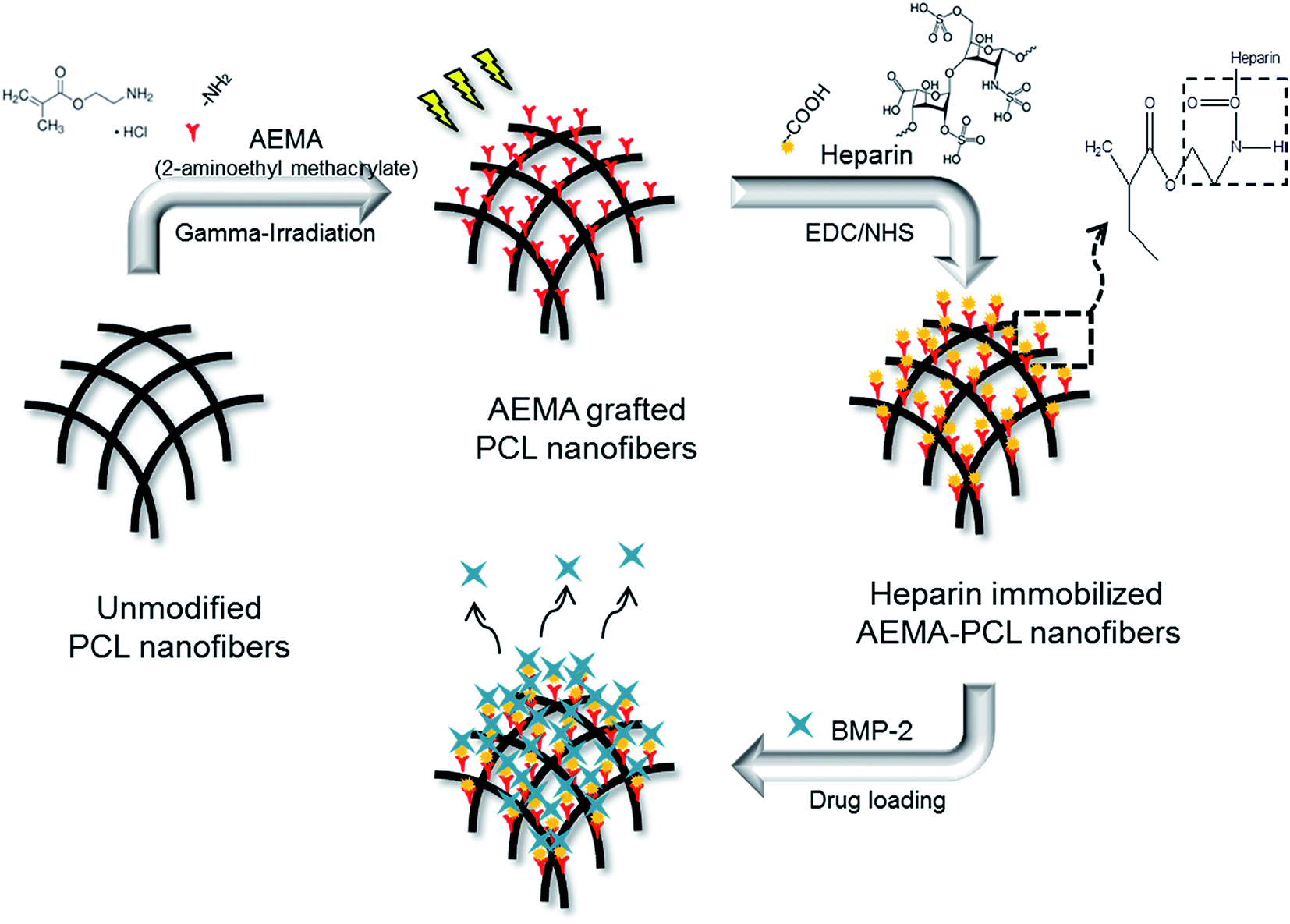 | ||
| Fig. 1 Schematic diagram for the preparation of heparin-immobilized AEMA–PCL nanofibers by using gamma-irradiation. | ||
| Sample | Concentration of AEMA (wt%) | Immobilization of heparin |
|---|---|---|
| PCL | — | — |
| 1AEP | 1 | — |
| 5AEP | 5 | — |
| 7AEP | 7 | — |
| H-1AEP | 1 | O |
| H-5AEP | 5 | O |
| H-7AEP | 7 | O |
3.2. Characterization of AEMA-grafted PCL nanofibers
The pore size was also an important determinant for the cell migration rate inside the scaffold, as well as the time constant of biodegradation. The surface morphologies of AEP were observed by SEM with different amounts of AEMA among the PCL, 1AEP, 5AEP, and 7AEP groups as shown in Fig. 2(a–d). All scaffolds appeared in the interconnected network pore configuration, characterized by its membrane-like structure. The structure was uniformly distributed, and formed an interconnected pore structure. There were no obvious morphological differences between the different AEP groups, and the diameters of the fibrous structures were similar in all the groups: PCL (226.58 ± 6.08 nm), 1AEP (220.41 ± 3.44 nm), 5AEP (222.53 ± 8.36 nm), and 7AEP (228.91 ± 3.77 nm). Therefore, there was no breakage or deformation of nanofibers after grafting AEMA using gamma-irradiation. Previously, gelatin-immobilized acrylic acid (AAc)-grafted PLCL substrates and Arg-Gly-Asp (RGD)-immobilized AAc-grafted PLLA/BCP scaffolds were also observed to have similar surface morphologies.26,32–35 As shown in Fig. 2(e), the chemical properties of AEP were identified by ATR-FTIR, with the typical peaks of the carbonyl groups from PCL at 1700 cm−1. After grafting AEMA, the amino groups of AEMA were observed at 1610 cm−1. In addition, when the grafted AEMA content increased from 1 to 7 wt%, the peaks of strongest intensity were at 1610 cm−1 (–NH2 stretching).36,37 Thus, we found that the AEMA was successfully grafted onto the PCL. The ATR FT-IR spectra were similar to those of AEMA that include AEMA substrates.38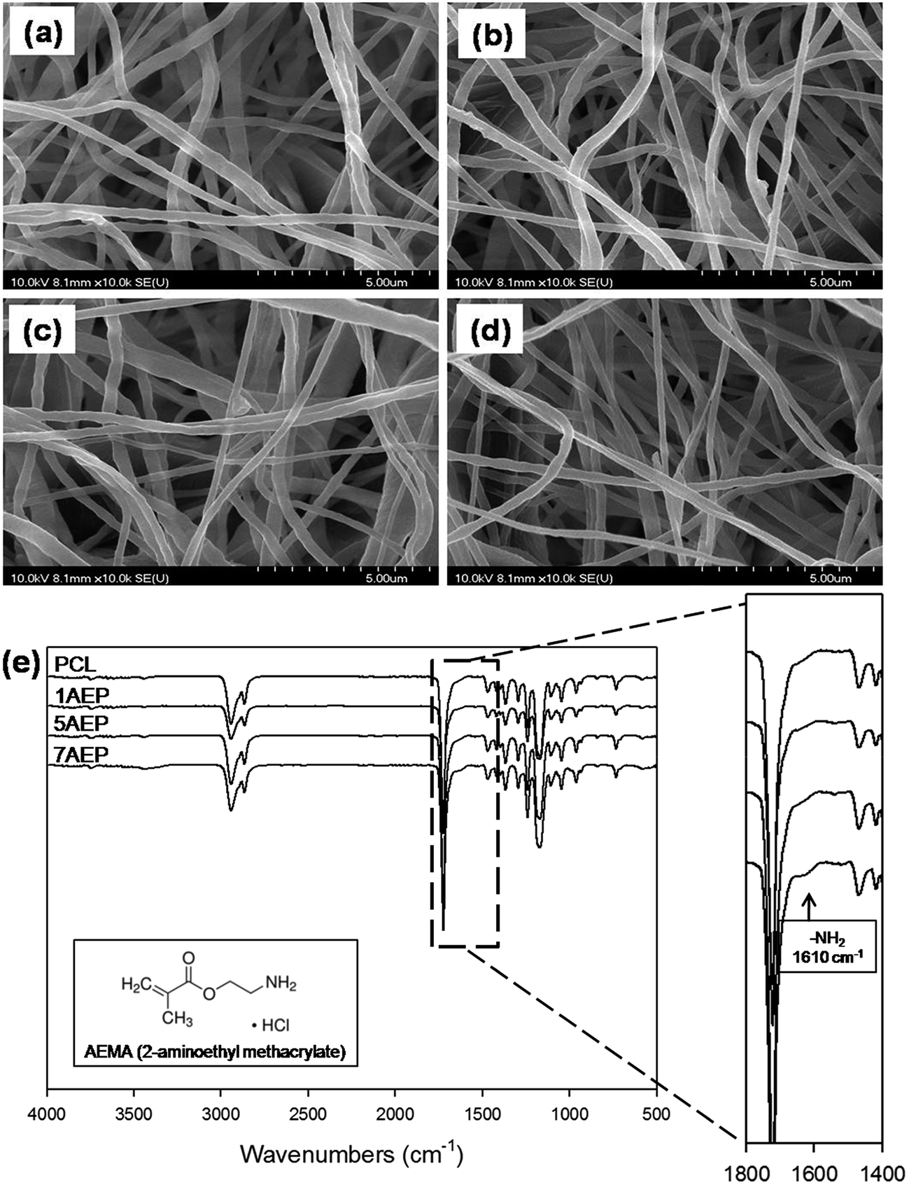 | ||
| Fig. 2 SEM images of AEMA-grafted PCL nanofibers: (a) PCL, (b) 1AEP, (c) 5AEP, (d) 7AEP, and (e) ATR-FTIR spectra of PCL, 1AEP, 5AEP, and 7AEP nanofibrous scaffolds. | ||
The surface composition after grafting AEMA on the PCL was observed by XPS, as shown in Fig. 3. The binding energy of PCL was located in the carbon peak (C1s peak at 287.5 eV) and oxygen peak (O1s peak at 532.3 eV), respectively. The nitrogen peak (N1s peak at 399 eV) was observed at 400 eV for the AEP.39 While the nitrogen peak was not found in PCL, the peak intensity of nitrogen was strongest in the 7AEP group, which had a higher concentration of AEMA compared to the 1AEP and 5AEP groups. These results suggest that the radiation-induced polymerization of AEMA-grafted PCL is successful at presenting methacrylate domains at the surface of PCL nanofibers without chemical additives such as initiators and catalysts.
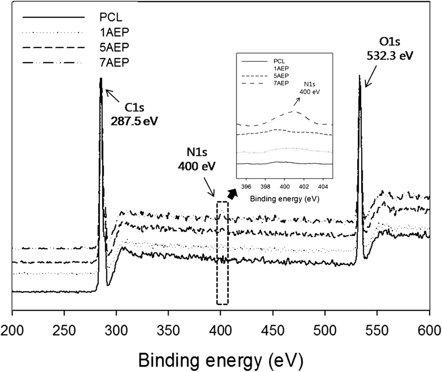 | ||
| Fig. 3 XPS spectra of AEMA-grafted PCL nanofibers from 200 to 600 eV. | ||
Qualification of AEMA grafted onto PCL nanofibrous scaffolds was confirmed with fluorescamine staining. The fluorescamine reacts with amino groups, as confirmed by use of a Leica DM1400B.27,34 As shown in Fig. 4, pure PCL scaffolds are black in color, while the AEP uniformly exhibited green staining which increased with increasing AEMA concentrations. The 7AEP scaffolds exhibited higher intensity than 1AEP and 5AEP. This noticeable amount of grafting may result from a higher number of amino groups from AEMA induced by gamma-irradiation.
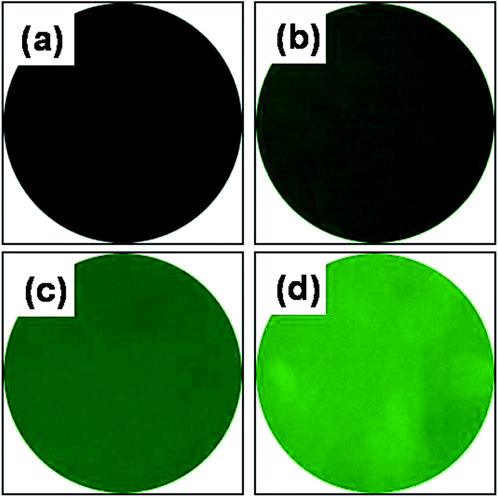 | ||
| Fig. 4 Fluorescamine staining of AEMA-grafted PCL nanofibers: (a) PCL, (b) 1AEP, (c) 5AEP, and (d) 7AEP. | ||
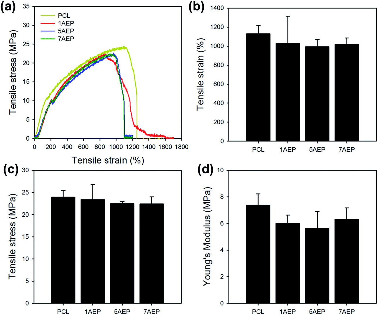
As shown in Fig. 5, the mechanical properties of PCL, 1AEP, 5AEP, and 7AEP were analyzed by UTM. The tensile stress of PCL was 23.97 ± 1.52 MPa, but for AEP was slightly decreased to 23.37 ± 1.52, 22.49 ± 0.47, and 22.46 ± 1.58 MPa according to AEMA contents of 1, 5, and 7 wt%, respectively. In addition, tensile strain and Young's modulus of AEP was also slightly decreased compared to PCL. The mechanical properties of irradiated PCL could be also decreased with increasing in irradiation dose due to significantly reduced nanofibers through both hardness and strength owing to increasing in crystallinity after irradiation.40 Although tensile stress, tensile strain, and Young's modulus were slightly decreased, there was almost no change in mechanical properties after AEMA was grafted using gamma-irradiation within the margin of error.
 | ||
| Fig. 5 Mechanical properties of AEMA-grafted PCL nanofibers: (a) tensile curve, (b) tensile strain, (c) tensile stress, and (d) Young's modulus. | ||
3.3. Characterization of heparin immobilized AEMA-grafted PCL nanofibers
The immobilization of heparin on the AEP was activated by EDC/NHS reaction, and the heparin was immobilized by composing amide bonds between amino groups of AEP and the carboxyl groups of heparin.24 As shown in Fig. 6(a–c), the H-AEP was identified by SEM, and the surface morphologies and fiber diameters of different H-AEP groups were similar, in keeping with the results shown in Fig. 2(a–d). In addition, the chemical properties of H-AEP were analyzed by ATR-FTIR as shown in Fig. 6(d). The amide I group (C![[double bond, length as m-dash]](https://www.rsc.org/images/entities/char_e001.gif) O stretching) and amide II group (N–H bending) were observed at 1650 cm−1 and 1550 cm−1, respectively,41–43 and peak intensities of amide I and amide II were increased after heparin immobilization. However, the amino group peak was decreased due to amide bond formation. In addition, the intensity of the peaks increased with increasing AEMA content.
O stretching) and amide II group (N–H bending) were observed at 1650 cm−1 and 1550 cm−1, respectively,41–43 and peak intensities of amide I and amide II were increased after heparin immobilization. However, the amino group peak was decreased due to amide bond formation. In addition, the intensity of the peaks increased with increasing AEMA content.
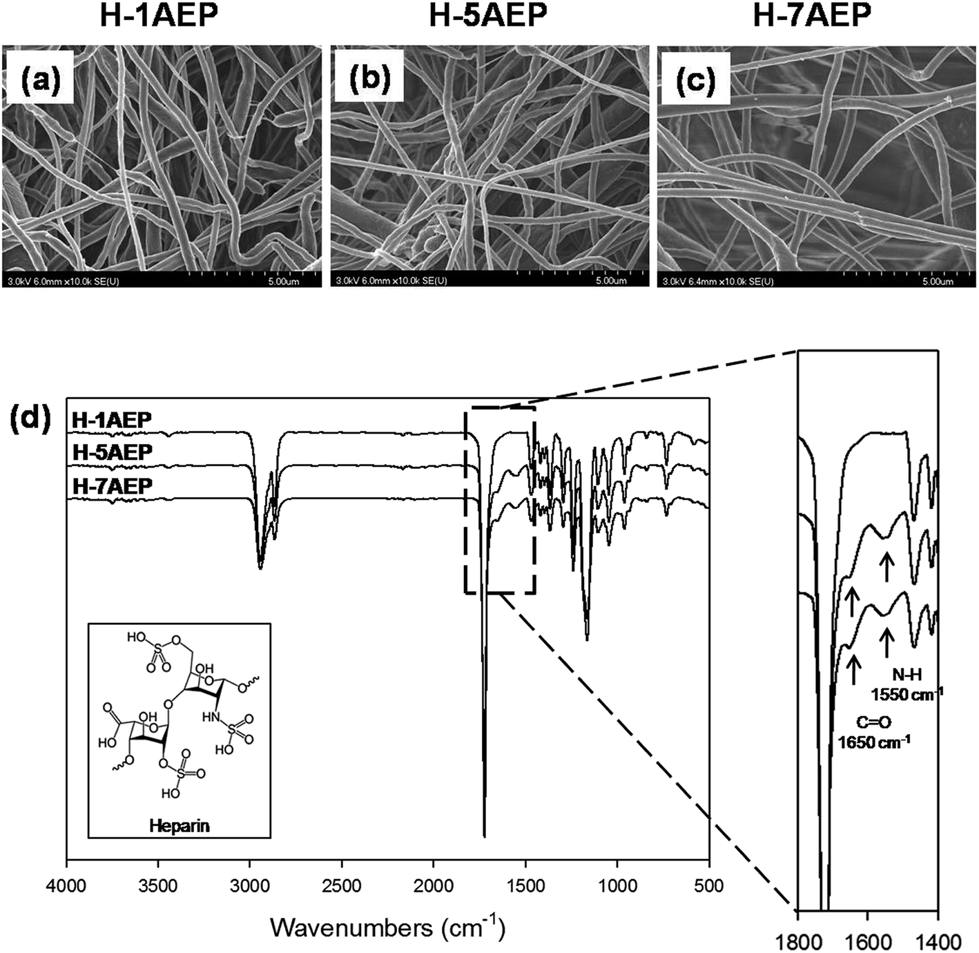 | ||
| Fig. 6 (a–c) SEM images and (d) ATR-FTIR spectra of H-1AEP, H-5AEP, and H-7AEP nanofibrous scaffolds. | ||
To quantify the carboxylic acid groups of heparin, a toluidine blue O (TBO) assay was used. As shown in Fig. 7(a), whereas PCL was not changed in color, the H-AEP was stained blue, with intensity also increasing according to AEMA content.44 When the AEMA content was increased, as shown in Fig. 7(b), the amounts of TBO from the PCL and H-AEP were approximately 0, 0, 4.62 ± 1.64, and 7.35 ± 0.32 mM mg−1, respectively. Therefore, heparin was successfully introduced by the EDC/NHS reaction, as confirmed by positive results from the TBO assay.
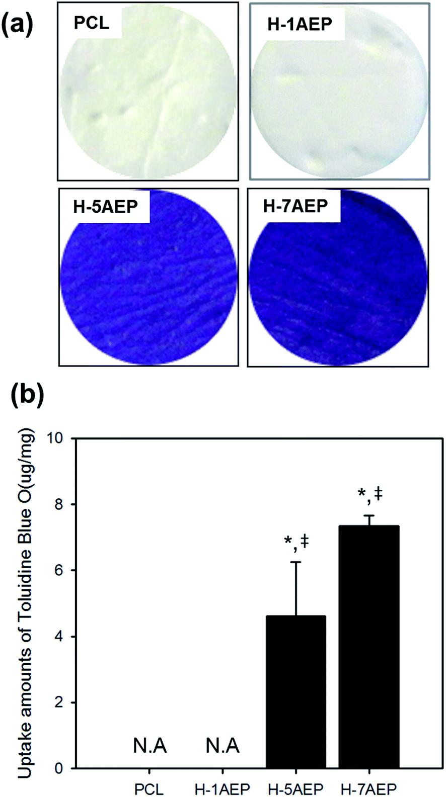 | ||
| Fig. 7 (a) Staining and (b) uptake amounts of toluidine blue O (TBO) of PCL, H-1AEP, H-5AEP, and H-7AEP nanofibrous scaffolds.“*” Indicates statistical significance relative to the PCL, and “‡” relative to the H-1AEP (p < 0.05). | ||
3.4. Human mesenchymal stem cell viability
The AEP allowed increased cell adhesion and proliferation of hMSCs, which highlights the importance of developing tissue engineering applications that focus on initial adhesion in order to regulate cell survival. As shown in Fig. 8(a–h), when hMSCs were cultured after 1 day, there was more adhesion on the AEP compared to PCL, as confirmed by SEM images and fluorescence photomicrographs;39 as the AEMA content increased, the adhesion of hMSCs also increased slightly. In addition, as shown in Fig. 8(i), the cell viability of hMSCs on PCL and 7AEP was 0.96 ± 0.23 and 1.05 ± 0.14, respectively, indicating that hMSC proliferation on 7AEP was greater than on PCL, as confirmed by CCK-8 assay. This result suggests that the radiation technology used for surface modification can modify a hydrophobic surface to a hydrophilic surface without chemical additives such that cell adhesion and proliferation could be increased. However, as shown in Fig. 9(a–f), adhesion of hMSCs on the H-AEP was less spread out than on PCL, indicating that hMSCs on the H-AEP were growing more slowly as time went on. The proliferation of hMSCs is presented in Fig. 9(g); initial proliferation on the H-AEP was slow compared to the PCL. Results from the assay demonstrated significantly greater cell adhesion and proliferation on the heparin-modified materials compared to the unmodified. Also, we wanted to determine the effect of released BMP-2 from the scaffolds on hMSCs proliferation. By day seven, all scaffolds releasing BMP-2 resulted in increased cell number compared to the control (PCL), and there was increased cell number in the heparin-modified scaffold condition compared to the unmodified scaffold condition (Fig. 10).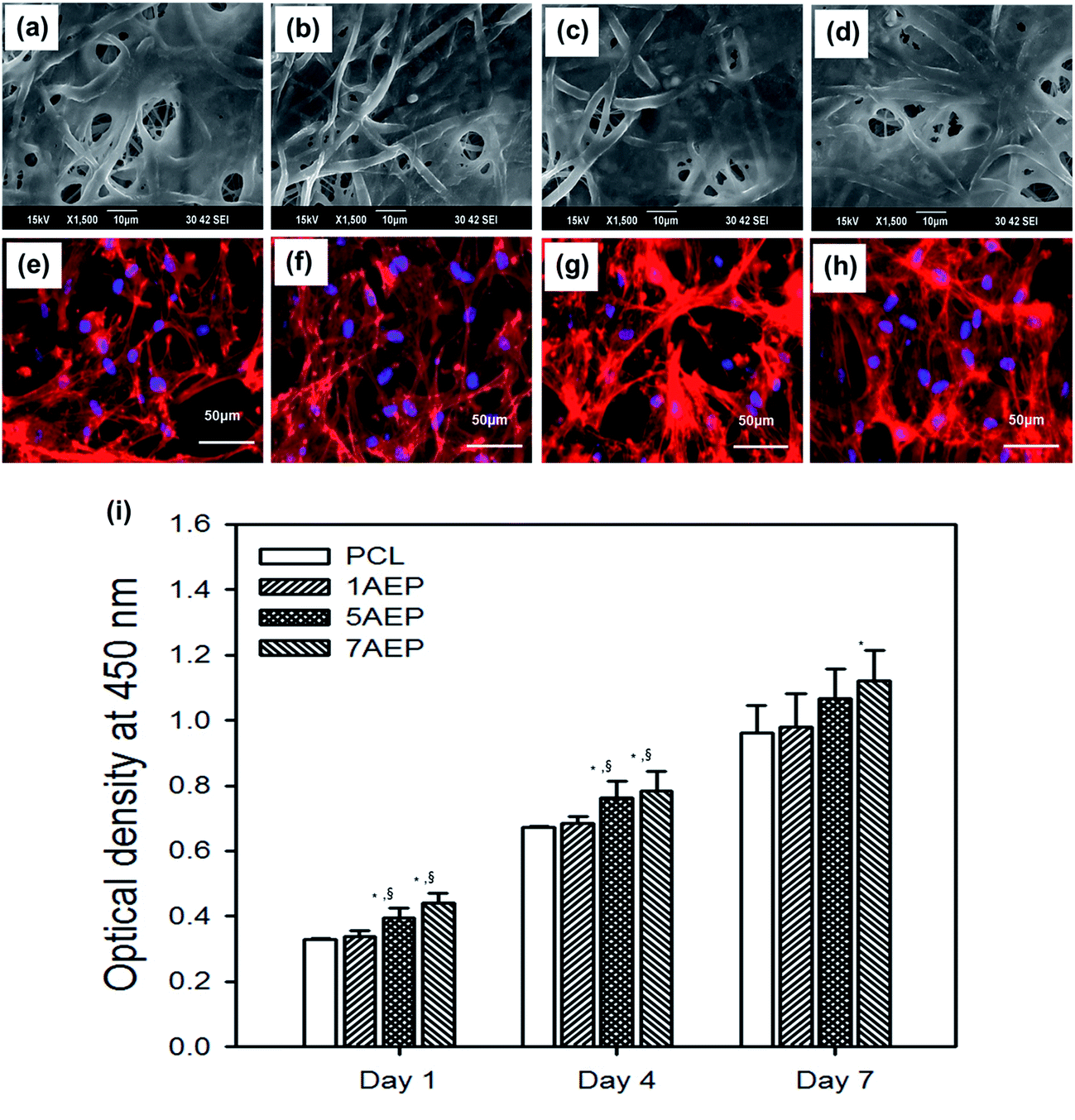 | ||
| Fig. 8 SEM images and fluorescence photomicrographs of hMSCs cultured on (a, e) PCL, (b, f) 1AEP, (c, g) 5AEP, and (d, h) 7AEP nanofibrous scaffolds stained with rhodamine-phalloidin and DAPI. Scale bars represent 50 μm. (i) CCK-8 assay of hMSCs cultured on these nanofibrous scaffolds for 1, 4, and 7 days.“*” Indicates statistical significance relative to the PCL, “§” relative to the 1AEP, and “‡” relative to the H-1AEP (p < 0.05). | ||
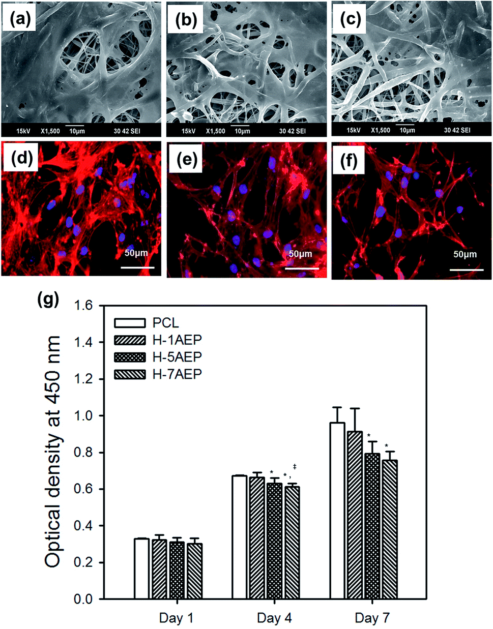 | ||
| Fig. 9 SEM images and fluorescence photomicrographs of hMSCs cultured on (a, d) H-1AEP, (b, e) H-5AEP, and (c, f) H-7AEP nanofibrous scaffolds stained with rhodamine-phalloidin and DAPI. Scale bars represent 50 μm. (g) CCK-8 assay of hMSCs cultured on these nanofibrous scaffolds for 1, 4, and 7 days.“*” Indicates statistical significance relative to the PCL, “§” relative to the 1AEP, and “‡” relative to the H-1AEP (p < 0.05). | ||
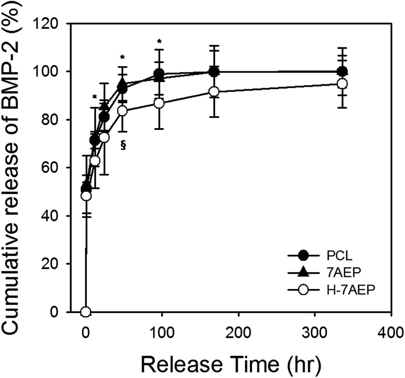 | ||
| Fig. 10 Cumulative release profiles of BMP-2 from PCL, 7AEP, and H-7AEP nanofibrous scaffolds for 336 h (14 days) “*” indicates statistical significance relative to the PCL, “§” relative to the 7AEP (p < 0.05). | ||
3.5. Release test
BMP-2 was loaded for 1 h to bind with heparin and later allowed to release for 14 days. After 1 day, the cumulative release of BMP-2 from PCL, 7AEP, and H-7AEP was approximately 81.02 ± 5.79, 85.30 ± 9.81, and 72.53 ± 15.48%, respectively. Therefore, BMP-2 release was decreased in H-7AEP compared to PCL, suggesting that the BMP-2 was being slowly and continuously released from the H-7AEP as time went on due to controlling effect of heparin.4. Conclusion
In this study, to develop a biomaterial for effective regeneration in tissues, the PCL nanofibrous scaffolds were prepared by electrospinning to graft with AEMA using gamma-irradiation without chemical additives. After grafted AEMA, the heparin was then immobilized to the AEMA grafted PCL scaffolds by EDC/NHS reaction for the purpose of bone tissue engineering. The surface, chemical, and physical properties, and of these scaffolds were observed by characterization. Thus there were confirmed that AEMA and heparin were successfully and uniformly immobilized onto the PCL scaffolds through the gamma-irradiation. The modified scaffolds are successfully promoted functionalized with AEMA and heparin by radiation, and the controlled release of BMP-2 depending on immobilized heparin that was slowly released in a more biocompatible manner. Therefore, this strategy using radiation technology could be useful biomimetic scaffold applications.Acknowledgements
This research was supported by the National Nuclear R&D program through the National Research Foundation of Korea (NRF) funded by the Ministry of Science, ICT, and Future Planning, Korea (2012M2A2A60113196).References
- D. H. R. Kempen, L. Lu, T. E. Hefferan, L. B. Creemers, A. Maran, K. L. Classic, W. J. A. Dhert and M. J. Yaszemski, Biomaterials, 2008, 29, 3245–3252 CrossRef CAS PubMed.
- D. H. R. Kempen, L. Lu, A. Heijink, T. E. Hefferan, L. B. Creemers, A. Maran, M. J. Yaszemski and W. J. A. Dhert, Biomaterials, 2009, 30, 2816–2825 CrossRef CAS PubMed.
- I. Rajzer, E. Menaszek, R. Kwiatkowski and W. Chrzanowski, J. Mater. Sci.: Mater. Med., 2014, 25, 1239–1247 CrossRef CAS PubMed.
- I. Rajzer, E. Menaszek, R. Kwiatkowski, J. A. Planell and O. Castano, Mater. Sci. Eng., C, 2014, 44, 183–190 CrossRef CAS PubMed.
- Y. M. Shin, J.-S. Park, S. I. Jeong, S.-J. An, H.-J. Gwon, Y.-M. Lim, Y.-C. Nho and C.-Y. Kim, Biotechnol. Bioprocess Eng., 2014, 19, 341–349 CrossRef CAS.
- G. Wei and P. X. Ma, Biomaterials, 2004, 25, 4749–4757 CrossRef CAS PubMed.
- J. Xue, M. He, H. Liu, Y. Niu, A. Crawford, P. D. Coates, D. Chen, R. Shi and L. Zhang, Biomaterials, 2014, 35, 9395–9405 CrossRef CAS PubMed.
- S. I. Jeong, O. Jeon, M. D. Krebs, M. C. Hill and E. Alsberg, Eur. Cells Mater., 2012, 24, 331–343 CrossRef CAS PubMed.
- C. Zhou, Q. Shi, W. Guo, L. Terrell, A. T. Qureshi, D. J. Hayes and Q. Wu, Eur. Cells Mater., 2013, 5, 3847–3854 CAS.
- Z. Ma, C. Gao, Y. Gong and J. Shen, Biomaterials, 2005, 26, 1253–1259 CrossRef CAS PubMed.
- G. E. Park, M. A. Pattison, K. Park and T. J. Webster, Biomaterials, 2005, 26, 3075–3082 CrossRef CAS PubMed.
- S. Zaiss, T. Brown, J. Reichert and A. Berner, Materials, 2016, 9, 232 CrossRef.
- S. E. Bae, J. Choi, Y. K. Joung, K. Park and D. K. Han, J. Controlled Release, 2012, 160, 676–684 CrossRef CAS PubMed.
- T. Gao, W. Cui, Z. Wang, Y. Wang, Y. Liu, P. S. Malliappan, Y. Ito and P. Zhang, RSC Adv., 2016, 6, 20202–20210 RSC.
- M. D. Schofer, P. P. Roessler, J. Schaefer, C. Theisen, S. Schlimme, J. T. Heverhagen, M. Voelker, R. Dersch, S. Agarwal, S. Fuchs-Winkelmann and J. g. R. J. Paletta, PLoS One, 2011, 6, e25462 CAS.
- O. Jeon, S. J. Song, S.-W. Kang, A. J. Putnam and B.-S. Kim, Biomaterials, 2007, 28, 2763–2771 CrossRef CAS PubMed.
- S. E. Kim, S.-H. Song, Y. P. Yun, B.-J. Choi, I. K. Kwon, M. S. Bae, H.-J. Moon and Y.-D. Kwon, Biomaterials, 2011, 32, 366–373 CrossRef CAS PubMed.
- B. Li, Z. Lin, M. Mitsi, Y. Zhang and V. Vogel, Biomater. Sci., 2015, 3, 73–84 RSC.
- E. N. Bolbasov, M. Rybachuk, A. S. Golovkin, L. V. Antonova, E. V. Shesterikov, A. I. Malchikhina, V. A. Novikov, Y. G. Anissimov and S. I. Tverdokhlebov, Mater. Lett., 2014, 132, 281–284 CrossRef CAS.
- L. GrΦndahl, A. Chandler-Temple and M. Trau, Biomacromolecules, 2005, 6, 2197–2203 CrossRef PubMed.
- J. Z. Luk, J. Cooper-White, L. Rintoul, E. Taran and L. Grondahl, J. Mater. Chem. B, 2013, 1, 4171–4181 RSC.
- R. S. Benson, Nucl. Instrum. Methods Phys. Res., Sect. B, 2002, 191, 752–757 CrossRef CAS.
- N. M. El-Sawy, H. A. Abd El-Rehim and A. M. Elbarbary, Adv. Polym. Technol., 2011, 30, 21–32 CrossRef CAS.
- O. Jeon, C. Powell, L. D. Solorio, M. D. Krebs and E. Alsberg, J. Controlled Release, 2011, 154, 258–266 CrossRef CAS PubMed.
- E. Cottam, D. W. L. Hukins, K. Lee, C. Hewitt and M. J. Jenkins, Med. Eng. Phys., 2009, 31, 221–226 CrossRef PubMed.
- S. H. Lim and H.-Q. Mao, Adv. Drug Delivery Rev., 2009, 61, 1084–1096 CrossRef CAS PubMed.
- Y.-M. Lim, S. I. Jeong, Y. M. Shin, J.-S. Park, H.-J. Gwon, Y.-C. Nho, S.-J. An, J.-B. Choi, J.-O. Jeong and J.-W. Choi, Biotechnol. Bioprocess Eng., 2015, 20, 942–947 CrossRef CAS.
- J.-B. Huh, J.-J. Yang, K.-H. Choi, J. H. Bae, J.-Y. Lee, S.-E. Kim and S.-W. Shin, Int. J. Mol. Sci., 2015, 16, 16034–16052 CrossRef CAS PubMed.
- M. C. Phipps, W. C. Clem, J. M. Grunda, G. A. Clines and S. L. Bellis, Biomaterials, 2012, 33, 524–534 CrossRef CAS PubMed.
- J. R. Venugopal, S. Low, A. T. Choon, A. B. Kumar and S. Ramakrishna, Artif. Organs, 2008, 32, 388–397 CrossRef CAS PubMed.
- Y. M. Shin, J.-Y. Lim, J.-S. Park, H.-J. Gwon, S. I. Jeong and Y.-M. Lim, Biotechnol. Bioprocess Eng., 2014, 19, 118–125 CrossRef CAS.
- Y. M. Shin, T. G. Kim, J.-S. Park, H.-J. Gwon, S. I. Jeong, H. Shin, K.-S. Kim, D. Kim, M.-H. Yoon and Y.-M. Lim, J. Mater. Chem. B, 2015, 3, 2732–2741 RSC.
- Y. M. Shin, S.-Y. Jo, J.-S. Park, H.-J. Gwon, S. I. Jeong and Y.-M. Lim, Macromol. Biosci., 2014, 14, 1190–1198 CrossRef CAS PubMed.
- Y. Heo, Y. M. Shin, Y. B. Lee, Y. M. Lim and H. Shin, Colloids Surf., B, 2015, 134, 196–203 CrossRef CAS PubMed.
- Y. M. Shin, K.-S. Kim, Y. M. Lim, Y. C. Nho and H. Shin, Biomacromolecules, 2008, 9, 1772–1781 CrossRef CAS PubMed.
- J. Kadokawa, S. Saitou and S. Shoda, Carbohydr. Polym., 2005, 60, 253–258 CrossRef CAS.
- A. R. P. Figueiredo, A. G. P. R. Figueiredo, N. H. C. S. Silva, A. Barros-Timmons, A. Almeida, A. J. D. Silvestre and C. S. R. Freire, Carbohydr. Polym., 2015, 123, 443–453 CrossRef CAS PubMed.
- O. Töpfer and G. Schmidt-Naake, Macromol. Symp., 2007, 248, 239–248 CrossRef.
- H.-Y. Yu, J.-M. He, L.-Q. Liu, X.-C. He, J.-S. Gu and X.-W. Wei, J. Membr. Sci., 2007, 302, 235–242 CrossRef CAS.
- L. A. Bosworth, A. Gibb and S. Downes, J. Polym. Sci., Part B: Polym. Phys., 2012, 50, 870–876 CrossRef CAS.
- U. Edlund, S. Danmark and A.-C. Albertsson, Biomacromolecules, 2008, 9, 901–905 CrossRef CAS PubMed.
- C.-H. Chang, W.-Y. Huang, C.-H. Lai, Y.-M. Hsu, Y.-H. Yao, T.-Y. Chen, J.-Y. Wu, S.-F. Peng and Y.-H. Lin, Acta Biomater., 2011, 7, 593–603 CrossRef CAS PubMed.
- X.-J. Huang, D. Guduru, Z.-K. Xu, J. Vienken and T. Groth, Acta Biomater., 2010, 6, 1099–1106 CrossRef CAS PubMed.
- J. Lee, J. J. Yoo, A. Atala and S. J. Lee, Acta Biomater., 2012, 8, 2549–2558 CrossRef CAS PubMed.
Footnote |
| † These two authors contributed equally to this work. |
| This journal is © The Royal Society of Chemistry 2017 |