An H-shaped, small molecular non-fullerene acceptor for efficient organic solar cells with an impressive open-circuit voltage of 1.17 V†
Akhil
Gupta
*a,
Anushri
Rananaware
b,
Pedada
Srinivasa Rao
cd,
Duong
Duc La
b,
Ante
Bilic
e,
Wanchun
Xiang
 f,
Jingliang
Li
a,
Richard A.
Evans
g,
Sidhanath V.
Bhosale
c and
Sheshanath V.
Bhosale
*b
aInstitute for Frontier Materials, Deakin University, Waurn Ponds, Victoria 3216, Australia. E-mail: akhil.gupta@deakin.edu.au; Tel: +61 3 5247 9542
bSchool of Science, RMIT University, GPO Box 2476, Melbourne, Victoria 3001, Australia. E-mail: sheshanath.bhosale@rmit.edu.au; Tel: +61 3 9925 2680
cPolymers and Functional Materials Division, CSIR-Indian Institute of Chemical Technology, Hyderabad 500007, Telangana, India
dAcademy of Scientific and Innovative Research (AcSIR), CSIR-IICT, Hyderabad 500007, Telangana, India
eData61 CSIRO, Molecular and Materials Modelling, Docklands, Victoria 8012, Australia
fState Key Laboratory of Silicate Materials for Architectures, Wuhan University of Technology, 122 Luoshi Rd, Wuhan 430070, Hubei, P. R. China
gCSIRO Manufacturing, Bayview Avenue, Clayton South, Victoria 3169, Australia
First published on 6th April 2017
Abstract
A bifluorenylidene-functionalized, H-shaped, small molecular non-fullerene electron acceptor, 6,6′,6′′,6′′′-([9,9′-bifluorenylidene]-2,2′,7,7′-tetrayltetrakis(thiophene-5,2-diyl))tetrakis(2,5-bis(2-ethylhexyl)-3-(thiophen-2-yl)-2,5-dihydrop yrrolo[3,4-c]pyrrole-1,4-dione) (coded as H1), which used diketopyrrolopyrrole as terminal functionalities, was designed, synthesized and characterized. H1 displayed a very high optical absorption coefficient, good solubility and thermal stability, promising optoelectronic properties, and high electron mobility, and afforded an encouraging efficiency of 5.42% when paired with the archetypal electron donor poly(3-hexylthiophene).
1. Introduction
The development of renewable energy technologies via harnessing solar energy has received tremendous attention in recent years, mainly because of their potential advantages, such as low cost, light weight, and flexibility.1 Technologies such as solution-processed bulk heterojunction (BHJ) organic solar cells and dye-sensitized solar cells are the most common, well-studied and significantly understood strategies.1,2 The past decade, particularly the last five years, has seen dramatic development in this research area, and the research has spanned across material design, morphology control, device architecture, and structure–activity relationships. The design and synthesis of novel donor and acceptor materials has been a considerable component of organic solar cell research in the drive towards cost-effective and efficient devices. The best donor materials have provided power conversion efficiencies in excess of 10% using soluble fullerene acceptors, such as [6,6]-phenyl-C61-butyric acid methyl ester (PC61BM) and its C71 analogue (PC71BM).3 These double-digit efficiency numerals have cemented fullerenes as the acceptors of choice in the field of organic solar cells. Fullerene acceptors possess a number of advantages, such as good electron mobility, excellent solubility and the ability to form a favourable nanoscale network with versatile donor semiconducting components,4 which has made them the most studied acceptors over the past two decades. However, these fullerene acceptors are not only expensive but possess a number of potential drawbacks, such as restricted chemical and energetic tuning via structural amendments, weak absorption in the visible spectrum, and morphological instability, to name a few.5 Moreover, a large electron affinity can result in low open-circuit voltage (Voc). Such disadvantages encourage researchers to seek alternative structural formats; for instance, non-fullerene electron acceptors, which can compete with fullerene acceptors by retaining appealing properties, such as strong accepting strength, solubility, and thermal stability. Moreover, such non-fullerene acceptor formats must address the limitations of fullerene acceptors; for example, limited absorption in the visible region, structural diversity and electronic tunability. Therefore, the design and development of a potential non-fullerene acceptor based on such necessities is a challenge for both organic chemists and device physicists.In recent years, there has been a dramatic surge in the development of non-fullerene acceptors and research has indicated that thoughtfully designed target chromophores may rival the development of donor functionalities. Recent reports, for instance D. Meng et al.,6 Y. Lin et al.,7 Hwang et al.,8 Zhong et al.9 and A. Rananaware et al.,10 have not only demonstrated encouraging efficiencies but have shown unique structural formats to be used as non-fullerene acceptors. Although recent advances in the design and development of non-fullerene acceptors have been impressive,11 there still remains the need to develop materials which not only will have better properties in terms of solubility, stability, and strong accepting strength but have energy levels matching those of the conventional and conjugated polymeric and small molecular donor functionalities. Furthermore, in order to make these acceptors viable for practical applications, they must be easily synthesizable and be electronically and physically compatible with the commercially available donors, such as poly(3-hexylthiophene) (P3HT).
The design of most efficient and promising small molecular non-fullerene acceptors indicates that a target chromophore should be a conjugated structure, either through a combination of various building blocks (primarily donors and acceptors) or through the possession of a rigid, extended fused-ring backbone.7,8,10 With such criteria in mind and learning from the work reported by us and others, we also thought to evaluate unique structural formats. We observed that functionalities such as diketopyrrolopyrrole (DPP) and naphthalene diimide (NDI) are strong accepting units that can be integrated with other conjugated blocks, either donors or acceptors, and can generate targets that can fulfil most of the demanding requirements of efficient non-fullerene acceptors. The use of DPP, in particular, appealed to us as the chromophores bearing terminal DPP units (1) can achieve higher Voc, (2) are soluble in most of the common processing solvents, (3) exert good thermal and chemical stability, and (4) can be generated with simple, facile and easily scalable synthetic strategies. Such advantages are likely to be responsible for prompting interest in the design of chromophores based on terminal DPP units and the overall development of novel non-fullerene acceptors based on DPP functionality.
Fig. 1 reveals the molecular structure of the novel, H-shaped, small molecular non-fullerene electron acceptor, 6,6′,6′′,6′′′-([9,9′-bifluorenylidene]-2,2′,7,7′-tetrayltetrakis(thiophene-5,2-diyl))tetrakis(2,5-bis(2-ethylhexyl)-3-(thiophen-2-yl)-2,5-dihydropyrrolo[3,4-c]pyrrole-1,4-dione) (coded as H1), which was designed based on the central bifluorenylidene and terminal diketopyrrolopyrrole functionalities. The molecule H1 is a highly conjugated chromophore, which was designed by taking into account most of the structural requirements of an efficient non-fullerene acceptor. It is important to point out that the central 9,9′-bifluorenylidene (BF) functionality was reported by F. G. Brunetti et al. as a new generation of acceptor compounds for organic electronic applications.12 More recently, K. Rakstys et al. have reported the use of the BF functionality for a different type of photochemical cell, known as a perovskite cell.13 The proposed design of H1, which includes a combination of potential BF and DPP functionalities, provided solution-processable BHJ devices based on the blend of P3HT![[thin space (1/6-em)]](https://www.rsc.org/images/entities/char_2009.gif) :
:![[thin space (1/6-em)]](https://www.rsc.org/images/entities/char_2009.gif) H1 (1
H1 (1![[thin space (1/6-em)]](https://www.rsc.org/images/entities/char_2009.gif) :
:![[thin space (1/6-em)]](https://www.rsc.org/images/entities/char_2009.gif) 1 w/w), which affords a promising efficiency of 5.42% with a high Voc of 1.17 V. These efficiency and Voc values are among the highest numerals for a single-junction BHJ device incorporating a non-fullerene acceptor and the common donor polymer P3HT. This current work is a continuation of our efforts made in the design and development of small molecular chromophores for organic photovoltaic applications.14
1 w/w), which affords a promising efficiency of 5.42% with a high Voc of 1.17 V. These efficiency and Voc values are among the highest numerals for a single-junction BHJ device incorporating a non-fullerene acceptor and the common donor polymer P3HT. This current work is a continuation of our efforts made in the design and development of small molecular chromophores for organic photovoltaic applications.14
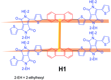 | ||
| Fig. 1 Molecular structure of the newly designed and synthesized non-fullerene electron acceptor H1. | ||
2. Results and discussion
H1 was purified via simple column chromatography and was found to be highly soluble in a variety of common organic solvents, such as chloroform, dichlorobenzene and tetrahydrofuran; for instance, >15 mg mL−1 in o-dichlorobenzene. The high solubility of the organic semiconducting materials is an essential requirement for fabricating solution-processable roll-to-roll organic photovoltaic devices and H1 undoubtedly fulfils this criterion.
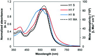
Fig. 2 shows the normalized spectra of optical absorption of H1 in chloroform solution, and in as-cast thin and blend films. In solution, H1 displayed a very high optical absorption coefficient (∼91![[thin space (1/6-em)]](https://www.rsc.org/images/entities/char_2009.gif) 000 L mol−1 cm−1 at 5.17 μM). A pristine film of H1 revealed significant absorption throughout the visible region (350–800 nm) with two peaks at 408 and 599 nm, and the longest wavelength absorption maximum (λmax) was red shifted by 10 nm compared to its solution λmax. The blend film using a combination of P3HT/H1 (1
000 L mol−1 cm−1 at 5.17 μM). A pristine film of H1 revealed significant absorption throughout the visible region (350–800 nm) with two peaks at 408 and 599 nm, and the longest wavelength absorption maximum (λmax) was red shifted by 10 nm compared to its solution λmax. The blend film using a combination of P3HT/H1 (1![[thin space (1/6-em)]](https://www.rsc.org/images/entities/char_2009.gif) :
:![[thin space (1/6-em)]](https://www.rsc.org/images/entities/char_2009.gif) 1) demonstrated strong light-harvesting ability over the entire visible zone, thus suggesting that there is an efficient charge transfer transition between the donor and acceptor domains. Furthermore, the photoluminescence studies were carried out on both the pristine and blend films of H1. The photoluminescence quenching measurement can provide valuable insight into the ability of the donor–acceptor interface to dissociate excitons. The presence of P3HT in the as-cast, blend films of P3HT
1) demonstrated strong light-harvesting ability over the entire visible zone, thus suggesting that there is an efficient charge transfer transition between the donor and acceptor domains. Furthermore, the photoluminescence studies were carried out on both the pristine and blend films of H1. The photoluminescence quenching measurement can provide valuable insight into the ability of the donor–acceptor interface to dissociate excitons. The presence of P3HT in the as-cast, blend films of P3HT![[thin space (1/6-em)]](https://www.rsc.org/images/entities/char_2009.gif) :
:![[thin space (1/6-em)]](https://www.rsc.org/images/entities/char_2009.gif) H1 (1
H1 (1![[thin space (1/6-em)]](https://www.rsc.org/images/entities/char_2009.gif) :
:![[thin space (1/6-em)]](https://www.rsc.org/images/entities/char_2009.gif) 1 w/w) quenched the photoluminescence (Fig. S1 in ESI†), thus indicating that an efficient photo-induced charge transfer occurs between H1 and P3HT in the blend film. This is further indicative of a more intimately mixed blend morphology.
1 w/w) quenched the photoluminescence (Fig. S1 in ESI†), thus indicating that an efficient photo-induced charge transfer occurs between H1 and P3HT in the blend film. This is further indicative of a more intimately mixed blend morphology.
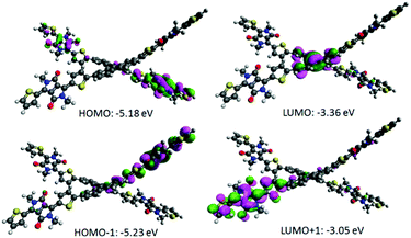
Density functional theory (DFT) calculations using the Gaussian 09 suite of programs15 and the B3LYP/6-311+G(d,p)//B3LYP/6-31G(d) level of theory indicated that the highest occupied molecular orbital (HOMO) and the lowest unoccupied molecular orbital (LUMO) densities are well segregated, a finding that assures an efficient charge transfer transition (Fig. 3). DFT calculations further revealed that the torsional angles between the internal thiophene ring planes (of DPP) and phenyl ring planes (of BF) were ∼20° and 50°, thus pointing out that H1 is a highly non-planar structure overall (Fig. S2, ESI†).
The central double bond joining the two fluorene components is twisted and is under strain. Calculations show it to be longer than a normal double bond (1.382 Å vs. standard 1.340 Å), indicating that it is under strain and primed for reduction. Given the precedence of research by Brunetti and Wudl12, which describes highly twisted double bonds between various aromatic structures and their ability to accept electrons, we would expect H1 to be similarly activated toward accepting an electron to relieve strain and increase aromaticity in the fluorene systems (angle twist in H1 = 40°). Once an electron is accepted, the radical anion formed will be stabilized, with the radical delocalized in one-half of the molecule and the anion delocalized in the other. In addition, non-planar molecular formats can be desirable for designing a potential non-fullerene acceptor, mainly due to the fact that such arrangements can prevent strong intermolecular aggregation whilst sustaining broadened conjugation in each direction for photon harvesting. We and others have recently demonstrated this principle while designing efficient non-fullerene electron acceptors.10,11a The experimental estimation of the HOMO energy level was carried out using photoelectron spectroscopy in air (PESA), and the LUMO level was calculated by adding the optical band gap (film spectrum) to the HOMO value. The HOMO and LUMO values were found to be −5.51 eV and −3.84 eV, respectively, thus suggesting that H1 is a low band gap material. Appropriately positioned energy levels of H1 suggested that it can certainly achieve a high Voc when fabricated using the conventional donor polymer P3HT. Theoretical calculations also revealed that H1 exerts a low band gap and a high HOMO level of 1.82 eV and −5.18 eV, respectively, a result that provides strong support to our experimental findings (Fig. S3, ESI,† for the PESA curve and Fig. 4 for the energy level diagram). The theoretical optical absorption transitions of H1 were also calculated and corroborated our experimental findings (Fig. S4, ESI†). We further realised that not only should organic semiconductors be highly soluble and chemically stable, they should also be thermally stable for allowing device processing, such as annealing, if required. Keeping this criterion in mind, we conducted thermogravimetric analysis (TGA). TGA demonstrated that the thermal stability of H1 is excellent (for TGA curve see Fig. S5, ESI†).
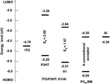 | ||
| Fig. 4 Energy level diagram showing alignments of different components of the BHJ device architecture. | ||
Once it had been established that H1 displayed appropriate optoelectronic properties, we evaluated its performance as a non-fullerene electron acceptor along with the classic electron donor P3HT in solution-processable BHJ devices under simulated sunlight and monochromatic light illumination. Solar cells using a conventional configuration of indium tin oxide (ITO)/poly(3,4-ethylenedioxythiophene):poly(styrene-sulfonate) (PEDOT:PSS, 38 nm)/active layer (∼68 nm)/Ca (20 nm)/Al (100 nm) were fabricated, where the active layer was a 1![[thin space (1/6-em)]](https://www.rsc.org/images/entities/char_2009.gif) :
:![[thin space (1/6-em)]](https://www.rsc.org/images/entities/char_2009.gif) 1 blend of P3HT
1 blend of P3HT![[thin space (1/6-em)]](https://www.rsc.org/images/entities/char_2009.gif) :
:![[thin space (1/6-em)]](https://www.rsc.org/images/entities/char_2009.gif) H1, spin-cast from o-dichlorobenzene on top of the PEDOT:PSS-coated substrate. Control devices based on P3HT:PC61BM were also fabricated. We chose a simple device architecture to start with, and observed the initial performance, stability, fabricating conditions and reproducibility of the BHJ devices. With regard to the fabrication of fullerene-free organic solar cells, it is becoming evident that the use of a high boiling point solvent, for instance dichlorobenzene, may affect device performance. The recent literature reported by us and others demonstrates such considerations.16 Based on such principles and our own understanding of the BHJ device architecture, the active films were spin-coated from o-dichlorobenzene solutions (1
H1, spin-cast from o-dichlorobenzene on top of the PEDOT:PSS-coated substrate. Control devices based on P3HT:PC61BM were also fabricated. We chose a simple device architecture to start with, and observed the initial performance, stability, fabricating conditions and reproducibility of the BHJ devices. With regard to the fabrication of fullerene-free organic solar cells, it is becoming evident that the use of a high boiling point solvent, for instance dichlorobenzene, may affect device performance. The recent literature reported by us and others demonstrates such considerations.16 Based on such principles and our own understanding of the BHJ device architecture, the active films were spin-coated from o-dichlorobenzene solutions (1![[thin space (1/6-em)]](https://www.rsc.org/images/entities/char_2009.gif) :
:![[thin space (1/6-em)]](https://www.rsc.org/images/entities/char_2009.gif) 1 donor
1 donor![[thin space (1/6-em)]](https://www.rsc.org/images/entities/char_2009.gif) :
:![[thin space (1/6-em)]](https://www.rsc.org/images/entities/char_2009.gif) acceptor w/w).
acceptor w/w).
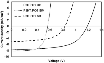
The current density–voltage (J–V) curves of the devices (with a D/A weight ratio of 1![[thin space (1/6-em)]](https://www.rsc.org/images/entities/char_2009.gif) :
:![[thin space (1/6-em)]](https://www.rsc.org/images/entities/char_2009.gif) 1) under different conditions measured under 100 mW cm−2 simulated sunlight illumination are shown in Fig. 5. The best as-cast device (device area = 0.1 cm2; a total of six devices were made) showed an impressive PCE of 5.42%, with a Voc of 1.17 V, a short-circuit current density (Jsc) of 7.74 mA cm−2 and a fill factor (FF) of 0.60. However, thermal annealing, for instance 100 °C for 10 minutes, of the active surface exerted an adverse effect on the device performance and the PCE dropped by approximately 50%. We noticed that this inferior photovoltaic performance was primarily due to the low film quality, where we physically observed roughness and minor cracks on the active surface after thermal annealing. Similar poor performance was observed for other D
1) under different conditions measured under 100 mW cm−2 simulated sunlight illumination are shown in Fig. 5. The best as-cast device (device area = 0.1 cm2; a total of six devices were made) showed an impressive PCE of 5.42%, with a Voc of 1.17 V, a short-circuit current density (Jsc) of 7.74 mA cm−2 and a fill factor (FF) of 0.60. However, thermal annealing, for instance 100 °C for 10 minutes, of the active surface exerted an adverse effect on the device performance and the PCE dropped by approximately 50%. We noticed that this inferior photovoltaic performance was primarily due to the low film quality, where we physically observed roughness and minor cracks on the active surface after thermal annealing. Similar poor performance was observed for other D![[thin space (1/6-em)]](https://www.rsc.org/images/entities/char_2009.gif) :
:![[thin space (1/6-em)]](https://www.rsc.org/images/entities/char_2009.gif) A combination, for example 1
A combination, for example 1![[thin space (1/6-em)]](https://www.rsc.org/images/entities/char_2009.gif) :
:![[thin space (1/6-em)]](https://www.rsc.org/images/entities/char_2009.gif) 1.5, indicating that the 1
1.5, indicating that the 1![[thin space (1/6-em)]](https://www.rsc.org/images/entities/char_2009.gif) :
:![[thin space (1/6-em)]](https://www.rsc.org/images/entities/char_2009.gif) 1 combination in the current study is the best possible combination in order to achieve high device outcome. Our physical observation of the 1
1 combination in the current study is the best possible combination in order to achieve high device outcome. Our physical observation of the 1![[thin space (1/6-em)]](https://www.rsc.org/images/entities/char_2009.gif) :
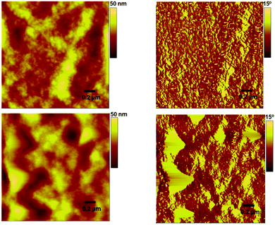
:![[thin space (1/6-em)]](https://www.rsc.org/images/entities/char_2009.gif) 1 combination (pre- and post-annealing film) was supported by an atomic force microscopy (AFM) analysis, which was conducted in tapping mode, where the surface roughness was more than doubled when compared to the unannealed surface, thereby indicating an irregular mixing of donor and acceptor domains (Fig. 6). The annealed device exhibited a PCE of 2.32%. In contrast, the maximum PCE reached 3.01% for a controlled device based on P3HT:PC61BM.
1 combination (pre- and post-annealing film) was supported by an atomic force microscopy (AFM) analysis, which was conducted in tapping mode, where the surface roughness was more than doubled when compared to the unannealed surface, thereby indicating an irregular mixing of donor and acceptor domains (Fig. 6). The annealed device exhibited a PCE of 2.32%. In contrast, the maximum PCE reached 3.01% for a controlled device based on P3HT:PC61BM.
The devices with H1 as an acceptor exhibited much higher Voc than the devices with PC61BM as an n-type semiconducting component (1.17 V vs. 0.56 V). The higher Voc in the case of H1 is consistent with the measured optical band gap between the LUMO of H1 and the HOMO of P3HT. Not only is H1 the first reported example in the literature where the amalgamated use of BF and DPP functionalities has been carried out to generate an efficient, H-shaped non-fullerene electron acceptor, but the PCE value reported here is among the highest values reported for P3HT and small molecular non-fullerene electron acceptor solar cells fabricated using a simple device architecture. The results achieved in the current work validate the use of an H-shaped or non-planar molecular format as a favourable structural concept for the design and development of highly efficient, small molecular non-fullerene acceptors for BHJ devices (see Table S1, ESI,† for detailed device parameters).
The incident photon-to-current conversion efficiency (IPCE) measurement of the blended film with a D/A weight ratio of 1![[thin space (1/6-em)]](https://www.rsc.org/images/entities/char_2009.gif) :
:![[thin space (1/6-em)]](https://www.rsc.org/images/entities/char_2009.gif) 1 is shown in Fig. 7. The blended film of the best photovoltaic device showed a broad IPCE spectrum ranging from 350 to 800 nm, typically over the entire visible region, with an IPCE maximum of approx. 42% at 596 nm. Apparently, the broadness of this IPCE spectrum suggests that H1 is a type of electron acceptor that can be blended with a variety of electron donors, for example conjugated polymers and small molecular donors, in order to achieve charge generation over a broad range of wavelengths. Photocurrents obtained from the IPCE data are in close agreement with those of current–voltage measurements.
1 is shown in Fig. 7. The blended film of the best photovoltaic device showed a broad IPCE spectrum ranging from 350 to 800 nm, typically over the entire visible region, with an IPCE maximum of approx. 42% at 596 nm. Apparently, the broadness of this IPCE spectrum suggests that H1 is a type of electron acceptor that can be blended with a variety of electron donors, for example conjugated polymers and small molecular donors, in order to achieve charge generation over a broad range of wavelengths. Photocurrents obtained from the IPCE data are in close agreement with those of current–voltage measurements.
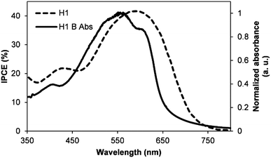 | ||
| Fig. 7 The IPCE curve of the best performing device described in Fig. 5 (H1 = IPCE spectrum of P3HT:H1 blend and H1 B Abs corresponds to P3HT:H1 blend absorption). | ||
The study of the actual surface morphology of the blend films of P3HT![[thin space (1/6-em)]](https://www.rsc.org/images/entities/char_2009.gif) :
:![[thin space (1/6-em)]](https://www.rsc.org/images/entities/char_2009.gif) H1 (1
H1 (1![[thin space (1/6-em)]](https://www.rsc.org/images/entities/char_2009.gif) :
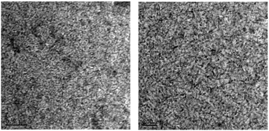
:![[thin space (1/6-em)]](https://www.rsc.org/images/entities/char_2009.gif) 1 w/w) is shown in Fig. 6. As mentioned above, the unannealed blend showed a smooth surface morphology with a root-mean-square (RMS) roughness of 3.6 nm, while the P3HT:H1 annealed blend displayed an RMS roughness of 8.6 nm. Although the blend surfaces indicated a strong domination of P3HT controlling the surface morphology, the unannealed blend appeared to be well interlaced, which is advantageous for exciton dissociation and can result in an enhanced efficiency of photovoltaic devices. Such a well-plaited surface was further confirmed by transmission electron microscopy (TEM) analysis, where we were able to observe a finer texture. This usually results in relatively higher values of Jsc and FF (Fig. 8). To gain insight into the effective charge carrier mobilities, the space charge limited current (SCLC) method was applied to get information about the charge transportation in the devices. The electron-only devices, consisting of an active layer sandwiched between a ZnO coated ITO electrode and LiF/Al counter-electrode as the hole-blocking contact, were fabricated as per the sketch depicted in Fig. S6, ESI.† From the current density as a function of the voltage data (Fig. S7, ESI†), the electron mobility in the trap-free SCLC region can be estimated using the Mott–Gurney equation [(J = 9(εμ)/8 × (V2/d3)), where ε is the dielectric constant, μ is the charge-carrier mobility, d is the sample thickness, and V is the applied voltage]. Using this expression, an excellent electron mobility of the order of 10−3 (2.40 × 10⁻³ cm2 V−1 s−1) was observed, which is beneficial for achieving higher Jsc and FF values with the resulting OPV devices.
1 w/w) is shown in Fig. 6. As mentioned above, the unannealed blend showed a smooth surface morphology with a root-mean-square (RMS) roughness of 3.6 nm, while the P3HT:H1 annealed blend displayed an RMS roughness of 8.6 nm. Although the blend surfaces indicated a strong domination of P3HT controlling the surface morphology, the unannealed blend appeared to be well interlaced, which is advantageous for exciton dissociation and can result in an enhanced efficiency of photovoltaic devices. Such a well-plaited surface was further confirmed by transmission electron microscopy (TEM) analysis, where we were able to observe a finer texture. This usually results in relatively higher values of Jsc and FF (Fig. 8). To gain insight into the effective charge carrier mobilities, the space charge limited current (SCLC) method was applied to get information about the charge transportation in the devices. The electron-only devices, consisting of an active layer sandwiched between a ZnO coated ITO electrode and LiF/Al counter-electrode as the hole-blocking contact, were fabricated as per the sketch depicted in Fig. S6, ESI.† From the current density as a function of the voltage data (Fig. S7, ESI†), the electron mobility in the trap-free SCLC region can be estimated using the Mott–Gurney equation [(J = 9(εμ)/8 × (V2/d3)), where ε is the dielectric constant, μ is the charge-carrier mobility, d is the sample thickness, and V is the applied voltage]. Using this expression, an excellent electron mobility of the order of 10−3 (2.40 × 10⁻³ cm2 V−1 s−1) was observed, which is beneficial for achieving higher Jsc and FF values with the resulting OPV devices.
3. Conclusions
In summary, a bifluorenylidene core-based non-fullerene electron acceptor, H1, with terminal DPP functionalities, was designed and synthesized. H1 possessed a non-planar molecular arrangement, excellent solubility, thermal stability and energy levels matching those of the classical donor polymer P3HT. Owing to the favourable morphology, good electron mobility and excellent high Voc of 1.17 V, the BHJ devices based on the P3HT:H1 blended films provided a PCE of 5.42%. Not only isH1 the first example in the literature that combines the structures of BF and DPP, but the device parameters outlined herein are among the best reported in the literature using a combination of a small molecular non-fullerene acceptor and the standard donor P3HT. The results indicate that H1 is a viable non-fullerene acceptor that can further be explored with a variety of donors, and that the 9,9′-BF moiety is very promising for futuristic molecular engineering of non-fullerene acceptors.4. Experimental section
4.1 Materials and methods
All reagents and chemicals used, unless otherwise specified, were purchased from Sigma-Aldrich Co. The solvents used for the reactions were obtained from Merck Speciality Chemicals (Sydney, Australia) and were used as received. 2,5-Bis(2-ethylhexyl)-3-(5-(4,4,5,5-tetramethyl-1,3,2-dioxaborolan-2-yl)thiophen-2-yl)-6-(thiophen-2-yl)-2,5-dihydropyrrolo[3,4-c]pyrrole-1,4-dione was purchased from SunaTech Inc., P. R. China, and was used as received. 2,2′,7,7′-Tetrabromo-9,9′-bifluorenylidene was synthesized according to the literature procedure.13Details of spectroscopic measurements, as well as device fabrication and characterization of photovoltaic devices, have been reported previously.14a,b,e,f AFM topographic maps were performed directly on the active layer of the P3HT:H1 blends using an Asylum Research MFP-3D-SA instrument. The AFM was run in intermittent contact mode (tapping mode) using MikroMasch NSC18 tips with a typical resonant frequency of ∼100 kHz, a typical probe radius of ∼10 nm, and a typical aspect ratio of 3![[thin space (1/6-em)]](https://www.rsc.org/images/entities/char_2009.gif) :
:![[thin space (1/6-em)]](https://www.rsc.org/images/entities/char_2009.gif) 1. TEM samples were prepared by solvent evaporation on a holey carbon grid and micrographs were produced using a JOEL 1010 100 kV TEM.
1. TEM samples were prepared by solvent evaporation on a holey carbon grid and micrographs were produced using a JOEL 1010 100 kV TEM.
4.2 Synthesis
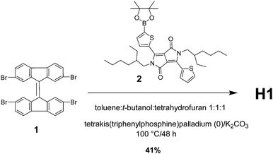
The synthetic procedure for the preparation of H1 was relatively simple and straightforward. It involved an industrially viable Suzuki coupling reaction between 2,2′,7,7′-tetrabromo-9,9′-bifluorenylidene and commercially available 2,5-bis(2-ethylhexyl)-3-(5-(4,4,5,5-tetramethyl-1,3,2-dioxaborolan-2-yl)thiophen-2-yl)-6-(thiophen-2-yl)-2,5-dihydropyrrolo[3,4-c]pyrrole-1,4-dione. The reaction was conducted at 100 °C using potassium carbonate (K2CO3) as the base and tetrakis(triphenylphosphine)palladium(0) [Pd(PPh3)4] as the catalyst (Scheme 1).The synthesis of 6,6′,6′′,6′′′-([9,9′-bifluorenylidene]-2,2′,7,7′-tetrayltetrakis(thiophene-5,2-diyl))tetrakis(2,5-bis(2-ethylhexyl)-3-(thiophen-2-yl)-2,5-dihydropyrrolo[3,4-c]pyrrole-1,4-dione) (H1) was performed as follows. To a stirred solution of 2 (488 mg, 0.75 mmol) in a solvent mixture of toluene![[thin space (1/6-em)]](https://www.rsc.org/images/entities/char_2009.gif) :
:![[thin space (1/6-em)]](https://www.rsc.org/images/entities/char_2009.gif) t-butanol
t-butanol![[thin space (1/6-em)]](https://www.rsc.org/images/entities/char_2009.gif) :
:![[thin space (1/6-em)]](https://www.rsc.org/images/entities/char_2009.gif) tetrahydrofuran (1
tetrahydrofuran (1![[thin space (1/6-em)]](https://www.rsc.org/images/entities/char_2009.gif) :
:![[thin space (1/6-em)]](https://www.rsc.org/images/entities/char_2009.gif) 1
1![[thin space (1/6-em)]](https://www.rsc.org/images/entities/char_2009.gif) :
:![[thin space (1/6-em)]](https://www.rsc.org/images/entities/char_2009.gif) 1) (30.0 mL) was added K2CO3 (103 mg, 0.75 mmol) and the resultant reaction mixture was degassed for 15 min followed by the addition of tetrakis(triphenylphosphine)palladium (0) (43 mg, 30 mol%). The resulting suspension was stirred for 30 min under a nitrogen atmosphere followed by the addition of compound 1 (80 mg, 0.124 mmol), and the cherry-coloured reaction mixture was stirred at 100 °C for 48 h. The reaction mixture was quenched with water and extracted with chloroform (3 × 30 mL). The combined organic layers were washed with water followed by brine, dried over anhydrous MgSO4 and concentrated under vacuum to produce a crude residue, which was purified by traditional column chromatography (hexane
1) (30.0 mL) was added K2CO3 (103 mg, 0.75 mmol) and the resultant reaction mixture was degassed for 15 min followed by the addition of tetrakis(triphenylphosphine)palladium (0) (43 mg, 30 mol%). The resulting suspension was stirred for 30 min under a nitrogen atmosphere followed by the addition of compound 1 (80 mg, 0.124 mmol), and the cherry-coloured reaction mixture was stirred at 100 °C for 48 h. The reaction mixture was quenched with water and extracted with chloroform (3 × 30 mL). The combined organic layers were washed with water followed by brine, dried over anhydrous MgSO4 and concentrated under vacuum to produce a crude residue, which was purified by traditional column chromatography (hexane![[thin space (1/6-em)]](https://www.rsc.org/images/entities/char_2009.gif) :
:![[thin space (1/6-em)]](https://www.rsc.org/images/entities/char_2009.gif) diethyl ether 9
diethyl ether 9![[thin space (1/6-em)]](https://www.rsc.org/images/entities/char_2009.gif) :
:![[thin space (1/6-em)]](https://www.rsc.org/images/entities/char_2009.gif) 1) to afford H1 as a light bluish solid with a metallic lustre (120 mg, 41%); 1H NMR (400 MHz, CDCl3) δ 8.92 (dd, J = 3.9, 1.1 Hz, 1H), 8.88 (d, J = 3.8 Hz, 1H), 8.41 (d, J = 1.6 Hz, 1H), 7.71 (d, J = 3.9 Hz, 1H), 7.63 (dd, J = 5.0 Hz, 1.2 Hz, 1H), 7.56–7.50 (m, 2H), 7.29–7.27 (m, 1H), 4.08–4.00 (m, 4H), 1.87–1.83 (m, 2H), 1.34–1.22 (m, 16H), 0.89–0.83 (m, 12H); 13C NMR (100 MHz, CDCl3) δ 162.67, 142.32, 142.08, 141.17, 141.01, 140.13, 139.89, 139.38, 139.30, 138.93, 138.40, 137.56, 137.34, 132.28, 130.62, 130.37, 130.06, 128.95, 128.83, 128.51, 124.17, 108.26, 45.94, 39.25, 36.62, 31.58, 30.31, 23.22, 14.18, 10.59; MALDI-TOF (m/z) [M]+ 2417.1; found for C146H168N8O8S8. Elemental analysis calculated for C146H168N8O8S8 (%): C 72.48, H 7.00, N 4.63; found C 72.45, H 6.96, N 4.61.
1) to afford H1 as a light bluish solid with a metallic lustre (120 mg, 41%); 1H NMR (400 MHz, CDCl3) δ 8.92 (dd, J = 3.9, 1.1 Hz, 1H), 8.88 (d, J = 3.8 Hz, 1H), 8.41 (d, J = 1.6 Hz, 1H), 7.71 (d, J = 3.9 Hz, 1H), 7.63 (dd, J = 5.0 Hz, 1.2 Hz, 1H), 7.56–7.50 (m, 2H), 7.29–7.27 (m, 1H), 4.08–4.00 (m, 4H), 1.87–1.83 (m, 2H), 1.34–1.22 (m, 16H), 0.89–0.83 (m, 12H); 13C NMR (100 MHz, CDCl3) δ 162.67, 142.32, 142.08, 141.17, 141.01, 140.13, 139.89, 139.38, 139.30, 138.93, 138.40, 137.56, 137.34, 132.28, 130.62, 130.37, 130.06, 128.95, 128.83, 128.51, 124.17, 108.26, 45.94, 39.25, 36.62, 31.58, 30.31, 23.22, 14.18, 10.59; MALDI-TOF (m/z) [M]+ 2417.1; found for C146H168N8O8S8. Elemental analysis calculated for C146H168N8O8S8 (%): C 72.48, H 7.00, N 4.63; found C 72.45, H 6.96, N 4.61.
Acknowledgements
A. G. acknowledges Dr Gerry Wilson from the CSIRO Division of Manufacturing, Clayton, Victoria, Australia, for providing support through a visiting fellow position. A. G. is also thankful to the Alfred Deakin Fellowship Scheme at the Institute for Frontier Materials (IFM), Deakin University, Waurn Ponds, Victoria, Australia. S. V. B. (RMIT) acknowledges financial support from the Australian Research Council (ARC), Australia, under a Future Fellowship Scheme (FT110100152). A. G. and A. R. acknowledge various testing and analytical facilities at RMIT University, Deakin University, the CSIRO Clayton and Bio21 Institutes, and the University of Melbourne, Melbourne, Victoria, Australia. W. X. acknowledges the National Natural Science Foundation of China (Grant No 51502224 and 21501145) and the fundamental research funds for the central universities (Wuhan University of Technology, WUT; Grant No. 2015IVA052). SVB (IICT) thanks the TAPSUN programme for financial assistance under the NWP0054 project.Notes and references
- (a) G. Yu, J. Gao, J. C. Hummelen, F. Wudl and A. J. Heeger, Science, 1995, 270, 1789 CAS; (b) C. J. Brabec, N. S. Sariciftci and J. C. Hummelen, Adv. Funct. Mater., 2001, 11, 15 CrossRef CAS; (c) F. C. Krebs, Sol. Energy Mater. Sol. Cells, 2009, 93, 394 CrossRef CAS; (d) A. J. Heeger, Chem. Soc. Rev., 2010, 39, 2354 RSC; (e) L. T. Dou, J. B. You, Z. R. Hong, Z. Xu, G. Li, R. A. Street and Y. Yang, Adv. Mater., 2013, 25, 6642 CrossRef CAS PubMed.
- W. Xiang, A. Gupta, M. K. Kashif, N. Duffy, A. Bilic, R. A. Evans, L. Spiccia and U. Bach, ChemSusChem, 2013, 6, 256 CrossRef CAS PubMed.
- (a) Z. He, B. Xiao, F. Liu, H. Wu, Y. Yang, S. Xiao, C. Wang, T. P. Russell and Y. Cao, Nat. Photonics, 2015, 9, 174 CrossRef CAS; (b) S. H. Liao, H. J. Jhuo, P. N. Yeh, Y. S. Cheng, Y. L. Li, Y. H. Lee, S. Sharma and S. A. Chen, Sci. Rep., 2014, 4, 6813 CrossRef CAS PubMed; (c) B. Kan, M. Li, Q. Zhang, F. Liu, X. Wan, Y. Wang, W. Ni, G. Long, X. Yang, H. Feng, Y. Zuo, M. Zhang, F. Huang, Y. Cao, T. P. Russell and Y. Chen, J. Am. Chem. Soc., 2015, 137, 3886 CrossRef CAS PubMed; (d) S. Zhang, L. Ye, W. Zhao, B. Yang, Q. Wang and J. Hou, Sci. China: Chem., 2015, 58, 248 CrossRef CAS; (e) J. Zhao, Y. Li, G. Yang, K. Jiang, H. Lin, H. Ade, W. Ma and H. Yan, Nat. Energy, 2016, 1, 15027 CrossRef CAS.
- (a) Y. He and Y. Li, Phys. Chem. Chem. Phys., 2011, 13, 1970 RSC; (b) Y. Lin, Y. Li and X. Zhan, Chem. Soc. Rev., 2012, 41, 4245 RSC.
- R. Y. C. Shin, P. Sonar, P. S. Siew, Z. K. Chen and A. Sellinger, J. Org. Chem., 2009, 74, 3293 CrossRef CAS PubMed.
- D. Meng, D. Sun, C. Zhong, T. Liu, B. Fan, L. Huo, Y. Li, W. Jiang, H. Choi, T. Kim, J. Y. Kim, Y. Sun, Z. Wang and A. J. Heeger, J. Am. Chem. Soc., 2016, 138, 375 CrossRef CAS PubMed.
- (a) Y. Lin, Q. He, F. Zhao, L. Huo, J. Mai, X. Lu, C.-J. Su, T. Li, J. Wang, J. Zhu, Y. Sun, C. Wang and X. Zhan, J. Am. Chem. Soc., 2016, 138, 2973 CrossRef CAS PubMed; (b) Y. Lin, F. Zhao, Q. He, L. Huo, Y. Wu, T. C. Parker, W. Ma, Y. Sun, C. Wang, D. Zhu, A. J. Heeger, S. R. Marder and X. Zhan, J. Am. Chem. Soc., 2016, 138, 4955 CrossRef CAS PubMed.
- Y.-J. Hwang, H. Li, B. A. E. Courtright, S. Subramaniyan and S. A. Jenekhe, Adv. Mater., 2016, 28, 124 CrossRef CAS PubMed.
- Y. Zhong, M. T. Trinh, R. Chen, G. E. Purdum, P. P. Khlyabich and M. Sezen, et al. , Nat. Commun., 2015, 6, 8241 CrossRef PubMed.
- A. Rananaware, A. Gupta, J. Li, A. Bilic, L. Jones, S. Bhargava and S. V. Bhosale, Chem. Commun., 2016, 52, 8522 RSC.
- (a) S. Holliday, R. S. Ashraf, C. B. Nielsen, M. Kirkus, J. A. Rçhr, C.-H. Tan, E. C. Fregoso, A.-C. Knall, J. R. Durrant, J. Nelson and I. McCulloch, J. Am. Chem. Soc., 2015, 137, 898 CrossRef CAS PubMed; (b) J. Zhao, Y. Li, H. Lin, Y. Liu, K. Jiang, C. Mu, T. Ma, J. Y. L. Lai, H. Hu, D. Yu and H. Yan, Energy Environ. Sci., 2015, 8, 520 RSC; (c) Y. Lin, Z.-G. Zhang, H. Bai, Y. Yao, Y. Li, D. Zhu and X. Zhan, Energy Environ. Sci., 2015, 8, 610 RSC; (d) Y. Lin, Z.-G. Zhang, H. Bai, Y. Li, D. Zhu and X. Zhan, Adv. Mater., 2015, 27, 1170 CrossRef CAS PubMed; (e) X. Liu, Y. Xie, H. Zhao, X. Cai, H. Wu, S.-J. Su and Y. Cao, New J. Chem., 2015, 39, 8771 RSC; (f) X. Liu, Y. Xie, X. Cai, Y. Li, H. Wu, S.-J. Su and Y. Cao, RSC Adv., 2015, 5, 107566 RSC; (g) S. Li, W. Liu, M. Shi, J. Mai, T.-K. Lau, J. Wan, X. Lu, C.-Z. Li and H. Chen, Energy Environ. Sci., 2016, 9, 604 RSC; (h) W. Chenab and Q. Zhang, J. Mater. Chem. C, 2017, 5, 1275 RSC.
- F. G. Brunetti, X. Gong, M. Tong, A. J. Heeger and F. Wudl, Angew. Chem., Int. Ed., 2010, 49, 532 CrossRef CAS PubMed.
- K. Rakstys, M. Saliba, P. Gao, P. Gratia, E. Kamarauskas, S. Paek, V. Jankauskas and M. K. Nazeeruddin, Angew. Chem., Int. Ed., 2016, 55, 7464 CrossRef CAS PubMed.
- (a) A. Gupta, A. Ali, A. Bilic, M. Gao, K. Hegedus, B. Singh, S. E. Watkins, G. J. Wilson, U. Bach and R. A. Evans, Chem. Commun., 2012, 48, 1889 RSC; (b) A. Gupta, V. Armel, W. Xiang, G. Fanchini, S. E. Watkins, D. R. MacFarlane, U. Bach and R. A. Evans, Tetrahedron, 2013, 69, 3584 CrossRef CAS; (c) R. J. Kumar, Q. I. Churches, J. Subbiah, A. Gupta, A. Ali, R. A. Evans and A. B. Holmes, Chem. Commun., 2013, 49, 6552 RSC; (d) A. Gupta, A. Ali, T. B. Singh, A. Bilic, U. Bach and R. A. Evans, Tetrahedron, 2012, 68, 9440 CrossRef CAS; (e) A. M. Raynor, A. Gupta, H. Patil, A. Bilic and S. V. Bhosale, RSC Adv., 2014, 4, 57635 RSC; (f) H. Patil, A. Gupta, B. Alford, D. Ma, S. H. Privèr, A. Bilic, P. Sonar and S. V. Bhosale, Asian J. Org. Chem., 2015, 4, 1096 CrossRef CAS.
- M. J. Frisch, G. W. Trucks, H. B. Schlegel, G. E. Scuseria, M. A. Robb and J. R. Cheeseman, et al., Gaussian 09 revision D.01, Gaussian Inc., Wallingford CT, 2013 Search PubMed.
- (a) Y. Kim, C. E. Song, S.-J. Moon and E. Lim, Chem. Commun., 2014, 50, 8235 RSC; (b) Y. Lin, P. Cheng, Y. Li and X. Zhan, Chem. Commun., 2012, 48, 4773 RSC; (c) H. Patil, A. Gupta, A. Bilic, S. V. Bhosale and S. V. Bhosale, Tetrahedron Lett., 2014, 55, 4430 CrossRef CAS; (d) H. Patil, W. X. Zu, A. Gupta, V. Chellappan, A. Bilic, P. Sonar, A. Rananaware, S. V. Bhosale and S. V. Bhosale, Phys. Chem. Chem. Phys., 2014, 16, 23837 RSC.
Footnote |
| † Electronic supplementary information (ESI) available: PL, theoretical optical absorption, PESA, TGA and SCLC curves, and experimental spectra. See DOI: 10.1039/c7qm00084g |
| This journal is © the Partner Organisations 2017 |

