Anisotropic electrical conductivity of n-doped thin films of polymerizable liquid-crystalline perylene bisimide bearing a triethylene oxide chain and cyclotetrasiloxane rings†
Masahiro
Funahashi
Department of Advanced Materials Science, Faculty of Engineering, Kagawa University, 2217-20 Hayashi-cho, Takamatsu, Kagawa 761-0396, Japan. E-mail: m-funa@eng.kagawa-u.ac.jp; Fax: +81-87-864-2411; Tel: +81-87-864-2411
First published on 3rd January 2017
Abstract
A polymerizable liquid-crystalline perylene tetracarboxylic bisimide (PTCBI) derivative bearing a triethylene oxide chain and cyclotetrasiloxane rings was synthesized. The compound exhibited a lamello-columnar phase in which the electron transport channels and ion-conductive sublayers were nanosegregated. Time-of-flight measurements revealed that the electron mobility of the columnar phase was on the order of 10−3 cm2 V−1 s−1. Thin films of the compound were produced by a spin-coating method, and the resulting films were polymerized and insolubilized via exposure to the vapors of trifluoromethanesulfonic acid. The uniaxially aligned thin films were doped in an aqueous solution of sodium dithionite. The electrical conductivity of the as-deposited and polymerized films increased to 10−4 S cm−1 in the doped states because ionic species can penetrate the ion-conductive sublayers. The anisotropy in the electrical conductivity of the as-deposited and polymerized thin films exceeds 100 and 10, respectively, in the doped states.
Introduction
In organic electronic materials, controlling the supramolecular aggregation of π-conjugated units is one of the key factors. The self-organization of electro- and redox-active π-conjugated moieties in liquid crystalline phases is effective in enhancing the charge-carrier transport.1 Liquid-crystalline (LC) semiconductors that exhibit smectic2 and columnar phases3 have been applied to solution-processed electroluminescent devices,4 field-effect transistors (FETs),5 and solar cells.6In LC phases, dynamic nanosegregated structures are constructed from molecules consisting of incompatible parts.7 The author has previously reported LC perylene tetracarboxylic bisimide (PTCBI) derivatives bearing oligosiloxane moieties.8 These compounds exhibit nanosegregated columnar phases in which electron-transporting one-dimensional (1-D) stacks of PTCBI cores are surrounded by a liquid-like oligosiloxane mantle at room temperature.8a–c
Even in the columnar phases of PTCBI derivatives bearing bulky cyclotetrasiloxane rings, the electron mobility exceeds 0.1 cm2 V−1 s−1.8d Macroscopically aligned thin films of these compounds are produced by a spin-coating method. The nanostructure of the anisotropic spin-coated thin films can be insolubilized by acid-induced ring-opening polymerization (AIROP).8e
This LC nanosegregated structure can be utilized as an anisotropic field to couple the electronic function with ionic transport. Redox-active LC materials9 have a wide range of potential applications, including electrochromic devices, conductive materials, batteries, and thermoelectric conversion elements. For these materials, the control of ionic as well as electronic transport processes is indispensable for the effective operation of such devices.
Nanosegregated LC phases consisting of molecules bearing π-conjugated and immiscible moieties have been reported.10a,b Electrochromic phenylterthiophene derivatives bearing imidazolium moieties form a nanosegregated smectic phase in which hole-transporting and ion-conductive layers are integrated separately.10c,d Electrochromic thienoviologen derivatives have also been reported.10e,f LC molecules based on π-conjugated units and crown ethers have been designed.10g,h However, their electrical conductivities have not been studied.
Herein, a new LC PTCBI derivative bearing polymerizable cyclotetrasiloxane rings and a triethylene oxide chain that can be coordinated to ions is reported. A nanosegregated anisotropic structure consisting of electron-transporting π-stacks and ion-conductive sublayers is constructed and is fixed by the in situ AIROP, as shown in Fig. 1. Spin-coated thin films were polymerized by the in situ AIROP method.8e The conductivity of the polymerized thin films was increased by a factor of 106 after the films were doped in an aqueous solution of sodium dithionate, while the analogous compound without a triethylene oxide chain could not be doped. Uniaxially aligned thin films exhibited anisotropic electrical conductivity. The polymerized films exhibited electrochromism in organic solvents, while the non-polymerized films dissolved in the same organic solvents.
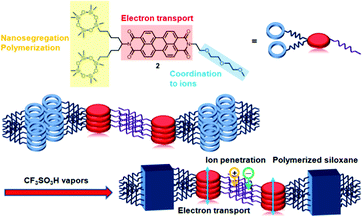 | ||
| Fig. 1 Schematic illustration of the construction of a nanosegregated LC structure and its fixation by the in situ AIROP. | ||
Poly(3,4-dioxythiophene)/polystyrenesulfonate (PDOT/PSS) derivatives are well known as solution-processable conductive conjugated polymers, in which holes are generated in the π-conjugated main chains.11 However, solution-processable, redox-active, n-type, organic semiconductors have been very limited.12 For n-type doping, reactive alkaline metals or strong donors are usually co-evaporated into n-type semiconductor thin films in a vacuum.12 The doping method proposed in this study involves dipping the thin films in a solution of sodium dithionate and does not require reactive donors. Due to the ion-conductive domains in the LC phase, the ionic reductant can penetrate into the thin film and can increase the doping level.
PTCBI derivatives are typical n-type organic semiconductors.13 The generation of anion radicals and dianions of PTCBI derivatives in solution states by chemical reactions and electrochemical methods has been investigated.14 However, studies on the generation of these anionic species in thin-film states have been limited.15 LC PTCBI derivatives have been mainly studied from the viewpoints of organic semiconductors and fluorescent materials.16 The electrical conductivity of thin films of n-doped LC PTCBI derivatives was reported by Gregg et al.17 However, the measurements were performed in the crystalline states. Therefore, no study has investigated the electrical conductivity of the LC phases of n-doped PTCBI derivatives to date.
Preparation of LC thin films with anisotropic conductivity has been limited although there have been a few studies on anisotropic carrier mobilities in the bulk LC states and FETs.18 No studies on doped LC thin films with anisotropic conductivity have been reported so far.
Experimental
Concept of molecular design
In this study, a LC PTCBI derivative bearing two polymerizable cyclotetrasiloxane rings and one triethylene oxide chain was synthesised. Oligosiloxane moieties have been used as the central cores of LC dendrimers and terminal groups of smectic LC molecules.19 In PTCBI derivatives bearing oligosiloxane moieties, the bulky oligosiloxane units inhibit crystallization but promote the formation of nanosegregated structures.8a–e These compounds form columnar phases at room temperature and exhibit high electron mobilities (>0.1 cm2 V−1 s−1). The solubility of such compounds in non-polar organic solvents is higher than 10 wt%, and thin films can be produced by a spin-coating method. In addition, a LC PTCBI derivative bearing disiloxane and triethylene oxide chains can be hybridized with a lithium salt in the LC phase.8fSpin-coated films of PTCBI derivatives bearing cyclotetrasiloxane rings can be polymerized in the LC thin-film states via exposure to the vapors of trifluoromethanesulfonic acid.8e This simple method produces nanostructured, organic–inorganic hybrid, thin films with element-block structures.20
Synthesis of LC PTCBI derivatives
The synthesis of asymmetric LC PTCBI derivatives has been previously reported in great detail.16f,j The LC PTCBI derivatives 1 and 2 (see Scheme 1) were synthesized according to a previously reported procedure.8f The treatment of perylene tetracarboxylic anhydride with alkenyl amine in the presence of zinc acetate in quinoline at 150 °C produced the PTCBI derivative 3 bearing four alkenyl groups. Compound 3 was partially hydrolyzed to produce compound 4. Compound 4 was reacted with hexylamine or methyl triglycolylamine in the presence of zinc acetate in quinoline at 150 °C to produce the asymmetric PTCBI derivatives 5 and 6, respectively. Compounds 5 and 6 were reacted with 1,3,3,5,5,7,7-heptamethylcyclotetrasiloxane in the presence of the Karstedt catalyst (bisdimethylvinylsiloxane platinum(0)),21 thereby producing compounds 1 and 2. The crude products 1 and 2 were purified repeatedly by silica gel column chromatography and reprecipitation in methanol.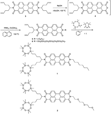 | ||
| Scheme 1 Synthetic route for producing the asymmetric LC PTCBI derivatives bearing cyclotetrasiloxane rings. | ||
Characterization of the mesophases
The mesomorphism of the PTCBI derivatives was studied by differential scanning calorimetry (DSC), a polarizing optical microscope (POM) equipped with a hot stage that was fabricated in-house, and X-ray diffraction (XRD).Measuring the carrier mobility of the LC phases
The electron mobilities were measured by the time-of-flight (TOF) method.22a For these measurements, a direct current (DC) bias was applied to a sandwich-type LC cell consisting of two indium tin oxide (ITO)-coated glass plates, and a pulsed-operation laser (wavelength = 356 nm) was illuminated on one side of the sample. The transit times for the photogenerated charge carriers to drift across the sample were determined from a kink point in the transient photocurrent curves.The samples were partially homeotropic. In the homeotropic domains, the LC columnar aggregates were aligned perpendicular to the electrode surface and parallel to the DC electric field, which caused the carrier transport to occur along the direction of the electric field. The experimental details are described in the ESI.†
Results and discussion
Characterization of the LC phases of compounds 1 and 2
Compounds 1 and 2 exhibited LC phases at room temperature because of the inhibited crystallization that was caused by the presence of bulky cyclotetrasiloxane rings, and the LC phases were retained when the samples were cooled to −100 °C. The LC phase of compound 2 was a lamello-columnar phase. One columnar aggregate of the LC phase included two π-stacks and one hydrophilic sublayer, while compound 1 exhibited a columnar phase in which single molecules stack. In addition, compound 2 does not crystallize as it is cooled to −100 °C, and the LC state was retained at room temperature for several months. During the heating process, the mesophase transitions to the second phase at 130 °C and melts to the isotropic phase at 178 °C. On cooling, a single mesophase is present below 176 °C and a glass transition occurs at around −50 °C. For compound 1, the high-temperature phase appears between 105 and 142 °C. The low-temperature phase is retained as the sample is cooled to −100 °C. Around −50 °C, a glass transition occurs, which is due to the thermal motion of the cyclotetrasiloxane rings (see Fig. S1 in the ESI†).Fig. 2 shows POM textures of compounds 1 and 2 at room temperature. For compound 1, hexagonal non-birefringent domains appeared during the phase transition from the isotropic phase to the high-temperature LC phase, which indicates the hexagonal symmetry of the columnar phase. When compound 1 is in the low-temperature phase, both slightly birefringent and highly birefringent domains with defect lines are observed, in which the columnar aggregates are aligned perpendicular and parallel to the substrate surface, respectively.
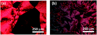 | ||
| Fig. 2 Micrographs of compounds (a) 1 and (b) 2 at room temperature, which were obtained with a POM. The thickness of the samples was 9 μm. | ||
In compound 2, both birefringent domains and non-birefringent domains with a defect line were observed during the phase transition from the isotropic phase to the LC phase. The birefringent domains grew in size to form fan-like textures, in which the molecules were oriented parallel to the substrate.
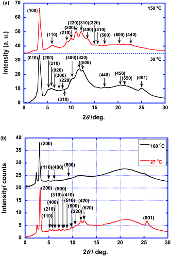
Fig. 3 shows the XRD patterns of compounds 1 and 2. For the high-temperature phase of compound 1, diffraction peaks are observed, which were assigned to the (100), (110), (210), (300), (220), (310), (400), (320), (410), (500), (440), and (600) diffraction planes. The ratio of the lattice constants indicates a hexagonal columnar arrangement. There is no (001) diffraction peak which is attributed to the π–π stacking within the columnar aggregates. Therefore, the high-temperature phase of compound 1 is a hexagonal columnar disordered phase. For the low-temperature phase, the diffraction peaks, which were assigned to the (010), (200), (210), (020), (300), (220), (400), (330), (500), (440), (450), and (550) diffraction planes, indicate a rectangular arrangement of the columnar aggregates with the symmetry of the P2m space group. The lattice constants were determined to be 34.8 and 27.3 Å. The (001) diffraction peak that originates from the π–π stacking within the columnar aggregates is present. Therefore, the low-temperature LC phase is a rectangular columnar ordered phase.
In contrast to compound 1, the LC phases of compound 2 have lamello-columnar structures. For the high-temperature phase, a strong peak at 3.01° and weak peaks at 5.0°, 6.1°, and 9.2° are present. These peaks were indexed to the (200), (110), (400), and (600) diffraction planes, respectively, by assuming a rectangular lattice with lattice constants of 58.7 and 18.5 Å. Broad halos that originate from the liquid-like packing of the cyclotetrasiloxane rings and alkyl chains are also present around 12° and 22°. There are no peaks indicating the presence of periodic π–π stacking within the columnar aggregates. Therefore, this high-temperature phase is a rectangular columnar disordered phase. For the low-temperature phase, the peaks in the XRD pattern were assigned to the (200), (110), (210), (400), (310), (500), (410), (510), (600), (220), (420), and (520) diffraction planes, which indicates a rectangular arrangement of the columnar aggregates. The lattice constants were determined to be 55.8 and 17.7 Å. In addition, a diffraction peak indexed to the (001) diffraction plane is present, indicating the presence of periodic π–π stacking within the columnar aggregates. Broad halos are present at approximately 12° and 21° that originate from the liquid-like packing of the cyclotetrasiloxane rings and alkyl chains, respectively.
The lattice constant of 55.8 Å is shorter than twice the molecular length (34 Å), but it is longer than the molecular length. It is plausible that sublayers should be formed in the columnar aggregates because of the interactions between the hydrophilic triethylene oxide chains. The columnar aggregates are organized into lamellar structures. Therefore, the low-temperature phase of compound 2 is a columnar rectangular ordered phase with P2mg symmetry.7g
Fig. 4 displays schematic illustrations of the columnar phases of compounds 1 and 2. For the columnar phases of compound 1, the molecules are stacked to form columnar aggregates that are staggered around the columnar axis.8b The alkyl chains and cyclotetrasiloxane rings of compound 1 are hydrophobic and form a liquid-like mantle surrounding the 1-D π-stacks. For the columnar phases of compound 2, hydrophilic sublayers (purple areas in Fig. 5(b)) are formed within the columnar aggregates through interactions between the hydrophilic triethylene oxide chains. The columnar aggregates are organized into a lamello-columnar structure. The sublayers formed within the columnar aggregates are hydrophilic and therefore metal ions can penetrate into the sublayers. On the other hand, the PTCBI cores also form electron-transporting 1-D π-stacks.
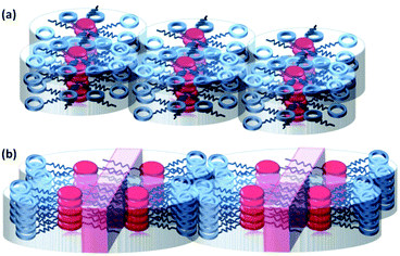 | ||
| Fig. 4 Schematic illustrations of the columnar phases of compounds (a) 1 and (b) 2. The purple area indicates an ion-penetrating sublayer. | ||
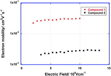 | ||
| Fig. 5 Electron mobility of the LC phases of compounds 1 and 2 as a function of the electric field at room temperature. | ||
Carrier-transport properties of compounds 1 and 2
The carrier-transport properties of the LC phases of compounds 1 and 2 were studied using the TOF method. Strong photocurrent signals for electrons were obtained in the LC phases of these compounds at room temperature. The transient photocurrent curves for electrons in the LC phases of compounds 1 and 2 above room temperature are non-dispersive (see Fig. S3 in the ESI†). In the columnar phase of compound 1, the electron mobility exceeds 3 × 10⁻² cm2 V−1 s−1. This result indicates that the Gaussian diffusion of electrons in ordered LC phases with a low defect density is efficient.In the lamello-columnar phase of compound 2, the electron mobility at room temperature was determined to be 2.5 × 10⁻³ cm2 V−1 s−1. In general, the carrier mobility along the columnar axis is much higher than that perpendicular to the axis. The photocurrent signals were weak compared to those obtained with compound 1, which is due to the tendency of the columnar aggregates to align homogenously.
When measuring the hole mobilities, only weak and featureless photocurrent decays were obtained with the LC phases of compounds 1 and 2. Thus, the hole mobilities could not be determined.
Fig. 5 shows the electron mobility of the LC phases of compounds 1 and 2 as a function of the electric field. The electron mobilities of these compounds are weakly dependent upon the electric field and temperature. The electron mobility of the ordered columnar phase of compound 1 is comparable to the hole mobilities of the ordered columnar phases of triphenylene derivatives,3a–c but it is slightly lower than the electron mobilities of the LC phases of PTCBI derivatives bearing oligosiloxane chains.8a–e The electron mobility in the columnar phase of compound 2 is one order of magnitude lower than that of compound 1. In the columnar phase of compound 1, a 1-D π–π-stacking structure with large π-orbital overlaps is formed, which results in efficient electron transport. However, in the lamello-columnar phase of compound 2, the π-orbital overlaps are not sufficient for efficient electron transport despite the presence of long-range positional ordering, which is attributed to the π–π-stacking structure.
The carrier mobility in the thin-film state could not be determined because the columnar axis was aligned parallel to the electrode surface, and thus, the photocurrent of the thin-film samples was very weak. Thus, the carrier mobility of the polymerized thin films could also not be characterized. However, electron transport paths should be retained in the polymerized thin films because doped thin films exhibited the electrical conductivity on the same order of those of non-doped thin films, as discussed later. For the study on the electron transport in the thin-film states, lateral TOF measurements in which the photogenerated charge carriers drift parallel to the substrate surface are in progress.22
Preparation of LC thin films of compounds 1 and 2
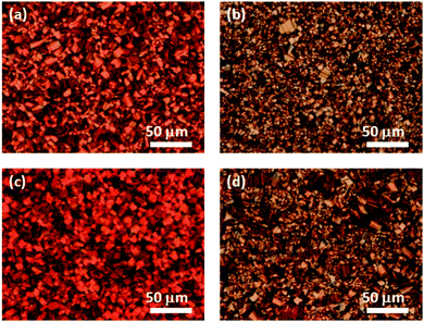
Compounds 1 and 2 are soluble in various organic solvents except for alcohols, and thin films were produced via spin-coating; toluene was used to produce the highest quality films. The thin films were produced from toluene solutions of compounds 1 or 2 (100 mg per ml). The thin films were dried at room temperature for 1 h and annealed at 160 °C for 2 h. The thickness of the resulting thin films was 200 nm.Fig. 6(a) and (b) shows POM textures of the spin-coated thin films. The micrographs show that domains of several tens of μm in size have formed in the thin films of both compounds. By comparing the XRD patterns, it was revealed that the molecular aggregation structures of the thin films were identical to those of the bulk LC phases, i.e., columnar rectangular ordered and lamello-columnar phases for compounds 1 and 2, respectively.
Polymerization of LC thin films of compounds 1 and 2
The in situ AIROP of compounds 1 and 2 in the LC thin-film states was carried out according to a modified version of a previously published procedure.8e A small glass tube containing several drops of trifluoromethanesulfonic acid was placed in a Petri dish, which was capped with another dish. The capped dish was placed in an oven and heated for 30 min at 80 °C, during which the volume of the dish was saturated with the vapors of the acid. The thin film deposited on a substrate was placed in the capped dish, which was then returned to the oven and heated for 30 min at 80 °C. After being exposed to the acidic vapors, the thin film was immersed in a toluene solution of triethylamine for 5 min to remove any absorbed acid from the polymerized film.Fig. 6(c) and (d) shows POM textures of the polymerized thin films. The domain structures of the thin films were unchanged by the polymerization process. The polymerized thin films were insoluble in various organic solvents, such as alcohol, chloroform, toluene, and tetrahydrofuran. In addition, the thickness of the thin films decreased to 150 nm during the polymerization process. The insolubilization process should proceed via the AIROP mechanism, which produces a polymer network.8e
The infrared (IR) transmittance spectra of the polymerized thin films of compounds 1 and 2 show that only the absorption band at 1080 cm−1, which is attributed to the stretching of Si–O bonds, was affected by the polymerization process (see Fig. S4 in the ESI†). This result indicates that the polymerization process involved a ring-opening mechanism.
The XRD patterns of the polymerized thin films of compounds 1 and 2 are ambiguous compared to those of the as-deposited thin films (see Fig. S5 in the ESI†). However, a few diffraction peaks that suggest the presence of columnar structures are present in the XRD patterns of the polymerized thin films of compounds 1 and 2. In the XRD pattern of compound 1, the (001) diffraction peak that is attributed to π–π stacking is present at 26°, while the π–π stacking structure of the polymerized thin film of compound 2 is not apparent. This result also suggests that the ring-opening polymerization involves the cyclotetrasiloxane rings located in the peripheral areas of the columnar aggregates. For a structural analysis of the polymerized films of compound 2, small angle X-ray diffraction is necessary because (100) diffraction could not be detected, due to the limitation of the apparatus.
Doping of as-deposited and polymerized thin films of compounds 1 and 2
The PTCBI derivatives are well-known n-type semiconductors. However, reports on the n-type doping of the PTCBI derivatives in solid states have been limited.12 The reduction of water-soluble PTCBI derivatives to dianions in an aqueous solution of sodium dithionite has been reported by several groups,14 although there have been very few studies on the generation of dianions and anion radicals of the PTCBI cores in thin-film states by chemical-reduction reactions.15 To dope the thin films of compounds 1 and 2, the films were dipped in an alkaline solution of sodium dithionite (0.1 M).Fig. 7 displays the photographs of the spin-coated thin films of compounds 1 and 2 in the initial and doped states. Interestingly, the color of the as-deposited and polymerized thin films of compound 2 changed from red to purple in the doping process while the red color of those of compound 1 was retained in the presence of dithionite anions.
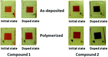 | ||
| Fig. 7 Photographs of spin-coated thin films of compounds 1 and 2. The as-deposited and polymerized thin films of compounds 1 and 2 are doped in the aqueous solution of sodium dithionite (0.2 M). | ||
Fig. 8 shows the absorption spectra of the as-deposited and polymerized thin films of compound 2 in the alkaline solution of sodium dithionite. In the doped thin films of compound 2, three peaks at 730 nm, 820 nm and 960 nm which were attributed to the radical anion of the PTCBI core and those at 570 nm and 630 nm which were originated from the dianion of the PTCBI core were present in the initial and polymerized states. However, the absorption spectra of the as-deposited and polymerized thin films of compound 1 did not change in the doping process (see Fig. S6 in the ESI†).
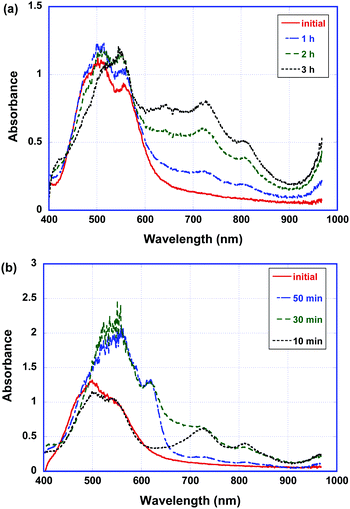 | ||
| Fig. 8 Absorption spectra of the (a) as-deposited and (b) polymerized thin films of compound 2 in the aqueous solution of sodium dithionite (0.2 M). | ||
Moreover, the polymerized thin films of compound 2 are reduced more rapidly in the sodium dithionite solution. In the polymerized thin films, most of the radical anions are reduced to dianions.
Anisotropic electrical conductivity of the LC spin-coated thin films of compounds 1 and 2
As reported previously,8e uniaxially aligned thin films of the LC PTCBI derivatives bearing cyclotetrasiloxane rings can be produced by the friction transfer method. Using the uniaxially aligned thin films, the anisotropy in the electrical conductivity of the LC PTCBI films was evaluated.ITO-coated glass plates were patterned via etching with concentrated hydrochloric acid to fabricate planar electrodes with a gap of 50 μm on the glass substrates. The patterned substrate was heated to 300 °C, and the surface of the substrate was rubbed by a Teflon stick. The surface-treated substrate was then spin-coated with the toluene solutions of compounds 1 and 2. The polymerization of the thin films was achieved via the in situ AIROP method. The radical anions and dianions of the PTCBI cores are stable in water, but are immediately reversibly oxidized to the neutral state upon exposure to oxygen in the atmosphere. However, the reduced states were stable for several hours in a plastic box filled with nitrogen gas when the doped film was covered with silicone oil and a glass coverslip.
Fig. 9 exhibits the polarized absorption spectra of the uniaxially aligned thin films of compound 2 in the initial and polymerized states. The dichroic ratios for the as-deposited and polymerized thin films were 12![[thin space (1/6-em)]](https://www.rsc.org/images/entities/char_2009.gif) :
:![[thin space (1/6-em)]](https://www.rsc.org/images/entities/char_2009.gif) 1 and 4
1 and 4![[thin space (1/6-em)]](https://www.rsc.org/images/entities/char_2009.gif) :
:![[thin space (1/6-em)]](https://www.rsc.org/images/entities/char_2009.gif) 1, respectively. The π-conjugated plane of the PTCBI cores orient perpendicular to the columnar axis and the absorption coefficient vertical to the columnar axis was larger than that parallel to it. As the X-ray diffraction pattern of the polymerized thin film of compound 2 suggests, the columnar structure should be disordered in the polymerization process because of the formation of a polymer network, as reported previously.8e However, the macroscopic columnar orientation was preserved in the polymerization process.
1, respectively. The π-conjugated plane of the PTCBI cores orient perpendicular to the columnar axis and the absorption coefficient vertical to the columnar axis was larger than that parallel to it. As the X-ray diffraction pattern of the polymerized thin film of compound 2 suggests, the columnar structure should be disordered in the polymerization process because of the formation of a polymer network, as reported previously.8e However, the macroscopic columnar orientation was preserved in the polymerization process.
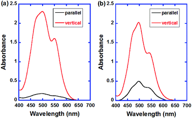 | ||
| Fig. 9 Polarized absorption spectra of the as-deposited and polymerized thin films of compound 2. The sample thickness is 2 × 10² nm. | ||
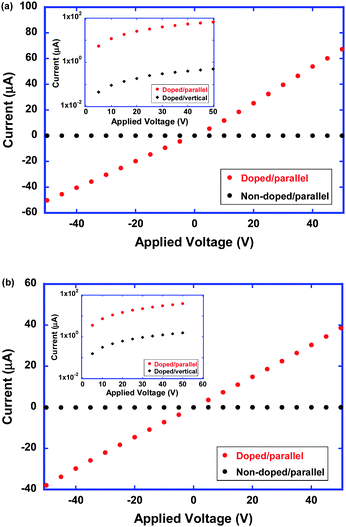
Fig. 10 shows the current–voltage characteristics of the as-deposited and polymerized thin films of compound 2 along the columnar axis at room temperature. In the neutral states, the electrical conductivities of the as-deposited and polymerized thin films were determined to be 1 × 10⁻¹⁰ and 2 × 10⁻¹⁰ S cm−1, respectively. The dark conductivities parallel and vertical to the columnar axis were almost on the same order. In the neutral state, the electron density was very low and the dark conductivity should be determined by charge carrier injection from the electrode.
In the doped states of as-deposited and polymerized thin films of compound 2, the electrical conductivities increase by 6 orders of magnitude from the order of 10−10 S cm−1 in the neutral state of the thin films. From the obtained current–voltage characteristics, the conductivity of the doped as-deposited and polymerized thin films were determined to be 3.0 × 10⁻⁴ and 2 × 10⁻⁴ S cm−1, respectively. Regarding the polymerized thin films, the disordered supramolecular aggregation structure should lead to a decrease in the electron mobility. However, the increased density of mobile electrons should compensate for the decreased electron mobility. Therefore, the electrical conductivity of the polymerized thin films of compound 2 should be comparable to that of the as-deposited thin films.
As shown in the insets of Fig. 10, it is noteworthy that the anisotropy in the electrical conductivity exceeded 102 and 10 in the as-deposited and polymerized thin films, respectively. The as-deposited thin film of compound 2 exhibited the high anisotropic absorption spectrum with the dichroic ratio exceeding 10, indicating a highly ordered 1D core–shell structure. Conductive 1D π-stacks which are surrounded by the insulative mantle consisting of cyclotetrasiloxane rings lead to the 1D electronic charge carrier transport. Even in the polymerized thin films, this 1D core–shell structure was preserved and the electrical conduction indicated a 1D nature.
It is also noted that the ion-conductive sublayers in the columnar aggregates of compound 2 play a significant role in the doping process. As shown in Fig. S6 (see the ESI†), anion radicals and dianions are not generated in the as-deposited and polymerized thin films of compound 1 by the doping process in the aqueous solution of sodium dithionite. Their electrical conductivities of the as-deposited and polymerized thin films were determined to be 3.2 × 10⁻¹⁰ and 1.1 × 10⁻⁹ S cm−1, respectively. After the doping process, those values increased by the factor of only 44 and 4.7 for the as-deposited and polymerized films, respectively (see Fig. S7 in the ESI†).
The effective doping of the thin films was possible with the as-deposited and polymerized thin films of compound 2, but not with those of compound 1. In the thin films of compound 1, the LC columnar aggregates are composed of hydrophobic moieties, and ionic species cannot penetrate the thin films. In contrast, the LC supramolecular structure of the thin films of compound 2 consists of hydrophilic sublayers and electro- and redox-active 1-D π-stacks. During the doping process, the sodium cations and dithionite anions can penetrate the thin films and the dithionite anions effectively reduce the π-conjugated PTCBI cores. In addition to the stabilization of ionic species penetrating into the hydrophilic sublayers, negative charges generated on the PTCBI cores should be stabilized by the polar triethylene oxide chains.23
Even in polydomain thin films which were deposited on untreated substrates, the electrical conductivities were on the order of 10−5 S cm−1 (see Fig. S8 in the ESI†).
By assuming that the electron mobility of the doped thin films of compound 2 is 10−3 cm2 V−1 s−1 (as determined from the TOF measurements), the electron density is estimated to be 6 × 1017 cm−3 when using a conductivity of 1.0 × 10⁻⁴ S cm−1. This electron density corresponds to 10 ppm of the molecular density. The concentration of dianions and anion radicals in the doped thin films was deduced to be several tens of mol%, although these anionic species were partially oxidized by oxygen in the atmosphere during the sample preparation and measurements. This result indicates that the cationic species, which compensate for the negative charges of the anionic species of the PTCBI cores, affect the electron transport process.
As proposed by Gregg et al.,17b,c sodium cations that penetrate the thin films should form Coulombic potential wells. The author of the present paper has also previously reported the effects of lithium-cation doping on LC PTCBI derivatives bearing a triethylene oxide chain.8f
Comparison with previously studied PTCBI derivatives
The doping of thin films of PTCBI derivatives was studied by Gregg et al.17 They synthesized PTCBI derivatives bearing an ammonium moiety, which were then reduced by sodium metal in a THF solution. The LC PTCBI derivatives were doped with the PTCBI anion radical salt and the conductivity of the mixture was measured. The conductivity increased to 10−3 S cm−1 when the dopant concentration was 0.1 mol%.16b,cThe doped samples were unstable under ambient conditions, which required the measurements to be carried out under inert conditions. Recently, the self-doping of the solid state of PTCBI derivatives bearing side chains that terminated with an amino group was observed.24 These PTCBI derivatives crystallized at room temperature, and the conductivities of such materials were only measured in the crystalline state. These doped systems were based on low molecular-weight molecules and polymerized thin films could not be produced.
The anisotropy in the carrier mobility in the columnar phase of LC triphenylene derivatives was determined to be around 105 by the TOF method.18a For doped LC triphenylene derivatives, the anisotropy in the AC conductivity was determined to be 103 at 10 Hz.18b For thin film samples, FETs were used to measure the anisotropy in the carrier mobility. Anisotropic carrier mobility has been observed in FETs based on uniaxially aligned chromonic18c and columnar LCs.18d In this study, the anisotropy in the electrical conductivity exceeds 100 and 10 in the non-polymerized and polymerized thin films, respectively. This is the first report on the anisotropic conductivity in the doped thin film state of LC semiconductors.
The electrochromism of PTCBI derivatives in solution states has been widely studied, and it is known that the anion radicals and dianions of PTCBI units are stable in water, but they are unstable upon exposure to oxygen.14a–d Reversible electrochromism was reported for thin films of polyimides and poly(ethylene oxide) containing PTCBI units in the main chains.15a,b Solution-processable PTCBI derivatives with low molecular weights are soluble in organic electrolyte solutions, and it is difficult to observe reversible electrochromism. In this study, the LC thin films of PTCBI derivatives were insolubilized via an acid-vapor-induced in situ ring-opening polymerization mechanism. The reversible electrochromism of the polymerized LC thin film state was thus observed. In electrochromism, ion-conductive domains are required for the efficient formation of electrical double layers. In electrochromic metallopolymers reported by Higuch et al., porous structures of the electrochromic thin films are effective for the penetration of electrolyte ions.25
Conclusions
In this study, a LC PTCBI derivative bearing a triethylene oxide chain and polymerizable cyclotetrasiloxane rings was synthesized. The compound exhibits a lamello-columnar phase with the P2mg symmetry, and the electron transport stacks and ion-conductive sublayers are integrated separately because of the nanosegregation between the triethylene oxide chains, hydrophobic cyclotetrasiloxane and aromatic groups. Thin films of the compound were produced using a spin-coating method, and the thin films were insolubilized by an acid-vapor-induced in situ polymerization process. The polymerized thin films exhibited electrochromism, which was caused by the formation of the anion radicals and dianions of the PTCBI cores. The as-deposited and polymerized thin films were doped in an aqueous solution of sodium dithionite. The electrical conductivity of the doped films increased to 10−4 S cm−1 because ionic species can penetrate the ion-conductive sublayers in the polymerized thin films. The anisotropy in the electrical conductivities exceeded 100 and 10 before and after the polymerization, respectively.Acknowledgements
This study was financially supported by a Grant-in-Aid for Scientific Research on Innovative Areas (Coordination Programming, no. 24108729, and Element-Block Polymers, JSPS KAKENHI Grant Number 15H00753) a Grant-in-Aid for Scientific Research (B) (JSPS KAKENHI Grant Number 15H03797) from the Japan Society for the Promotion of Science (JSPS), Grant-in-Aid for Challenging Exploratory Research (JSPS KAKENHI Grant Number 15K13677), the Asahi Glass Foundation, Iketani Science and Technology Foundation, Kato Foundation for Promotion of Science, and the Tokyo Electric Power Company (TEPCO) Memorial Foundation. The author would like to thank Dr A. Sonoda at the Health Research Institute of the National Institute of Advanced Industrial Science and Technology for assistance with NMR measurements. The author would also like to thank Prof. T. Ishii, Prof. T. Kusunose, and Prof. K. Isoda at Kagawa University for their assistance with the XRD analysis, DSC measurements, and the usage of a glove box, respectively.Notes and references
- (a) W. Pisula, M. Zorn, J. Y. Chang, K. Müllen and R. Zentel, Macromol. Rapid Commun., 2009, 30, 1179–1202 CrossRef CAS PubMed; (b) Y. Shimizu, K. Oikawa, K. Nakayama and D. Guillon, J. Mater. Chem., 2007, 17, 4223–4229 RSC; (c) M. O’Neill and S. M. Kelly, Adv. Mater., 2011, 23, 566–584 CrossRef PubMed; (d) M. Funahashi, H. Shimura, M. Yoshio and T. Kato, Struct. Bonding, 2008, 128, 151–179 CrossRef CAS; (e) M. Funahashi, T. Yasuda and T. Kato, Handbook of Liquid Crystals, Wiley-VCH, 2nd edn, 2014, vol. 8, pp. 675–708 Search PubMed; (f) S. Laschat, A. Baro, N. Steinke, F. Giesselmann, C. Hägele and G. Scalia, Angew. Chem., Int. Ed., 2007, 46, 4832–4887 CrossRef CAS PubMed.
- (a) M. Funahashi and J. Hanna, Phys. Rev. Lett., 1997, 78, 2184–2187 CrossRef CAS; (b) M. Funahashi and J. Hanna, Appl. Phys. Lett., 2000, 76, 2574–2576 CrossRef CAS; (c) M. Funahashi and J. Hanna, Adv. Mater., 2005, 17, 594–598 CrossRef CAS; (d) K. Oikawa, H. Monobe, J. Takahashi, K. Tsuchiya, B. Heinrich, D. Guillon and Y. Shimizu, Chem. Commun., 2005, 5337–5339 RSC; (e) A. Matsui, M. Funahashi, T. Tsuji and T. Kato, Chem. – Eur. J., 2010, 16, 13465–13472 CrossRef CAS PubMed; (f) H. Aboubakr, M.-G. Tamba, A. K. Diallo, C. Videlot-Ackermann, L. Belec, O. Siri, J.-M. Raimundo, G. H. Mehl and H. Brisset, J. Mater. Chem., 2012, 22, 23159–23168 RSC; (g) M. Funahashi, F. Zhang, N. Tamaoki and J. Hanna, ChemPhysChem, 2008, 9, 1465–1473 CrossRef CAS PubMed; (h) M. Funahashi, T. Ishii and A. Sonoda, ChemPhysChem, 2013, 14, 2750–2758 CrossRef CAS PubMed.
- (a) D. Adam, F. Closs, T. Frey, D. Funhoff, D. Haarer, H. Ringsdorf, P. Schuhmacher and K. Siemensmeyer, Phys. Rev. Lett., 1993, 70, 457–460 CrossRef CAS PubMed; (b) D. Adam, P. Schumacher, J. Simmerer, L. Haussling, K. Siemensmeyer, K. H. Etzbach, H. Ringsdorf and D. Haarer, Nature, 1994, 371, 141–143 CrossRef CAS; (c) N. Boden, R. J. Bushby, J. Clements, B. Movaghar, K. J. Donovan and T. Kreouzis, Phys. Rev. B: Condens. Matter Mater. Phys., 1995, 52, 13274–13280 CrossRef CAS; (d) A. M. van de Craats, J. M. Warman, A. Fechtenkötter, J. D. Brand, M. A. Harbison and K. Müllen, Adv. Mater., 1999, 11, 1469–1472 CrossRef CAS; (e) M. Ichihara, A. Suzuki, K. Hatsusaka and K. Ohta, Liq. Cryst., 2007, 34, 555–567 CrossRef CAS; (f) K. Ban, K. Nishikawa, K. Ohta, A. M. van de Craats, J. M. Warman, I. Yamamoto and H. Shirai, J. Mater. Chem., 2001, 11, 321–331 RSC; (g) A. Demenev, S. H. Eichhorn, T. Taerum, D. Perepichka, S. Patwardhan, F. C. Grozema and L. D. A. Siebbeles, Chem. Mater., 2010, 22, 1420–1428 CrossRef CAS; (h) J. Simmerer, B. Glüsen, W. Paulus, A. Kettner, P. Schuhmacher, D. Adam, K.-H. Etzbach, K. Siemensmeyer, J. H. Wendorf, H. Ringsdorf and D. Haarer, Adv. Mater., 1996, 8, 815–819 CrossRef CAS.
- (a) T. Hassheider, S. A. Benning, H.-S. Kitzerow, M.-F. Achard and H. Bock, Angew. Chem., Int. Ed., 2001, 40, 2060–2063 CrossRef CAS; (b) M. P. Aldred, A. E. A. Contoret, S. R. Farrar, S. M. Kelly, D. Mathieson, M. O'Neill, W. C. Tsoi and P. Vlachos, Adv. Mater., 2005, 17, 1368–1372 CrossRef CAS; (c) S. A. Benning, R. Oesterhaus and H.-S. Kitzerow, Liq. Cryst., 2004, 31, 201–205 CrossRef CAS.
- (a) A. J. J. M. van Breemen, P. T. Herwig, C. H. T. Chlon, J. Sweelssen, H. F. M. Schoo, S. Setayesh, W. M. Hardeman, C. A. Martin, D. M. de Leeuw, J. J. P. Valeton, C. W. M. Bastiaansen, D. J. Broer, A. R. Popa-Merticaru and S. C. J. Meskers, J. Am. Chem. Soc., 2006, 128, 2336–2345 CrossRef CAS PubMed; (b) M. Funahashi, F. Zhang and N. Tamaoki, Adv. Mater., 2007, 19, 353–358 CrossRef CAS; (c) A. M. van de Craats, N. Stutzmann, O. Bunk, M. M. Nielsen, M. Watson, K. Müllen, H. D. Chanzy, H. Sirringhaus and R. Friend, Adv. Mater., 2003, 15, 495–499 CrossRef CAS; (d) W. Pisula, A. Menon, M. Stepputat, I. Lieberwirth, U. Kolb, A. Tracz, H. Sirringhaus, T. Pakula and K. Müllen, Adv. Mater., 2005, 17, 684–689 CrossRef CAS; (e) M. Funahashi, Polym. J., 2009, 41, 459–469 CrossRef CAS; (f) F. Zhang, M. Funahashi and N. Tamaoki, Org. Electron., 2010, 11, 363–368 CrossRef CAS.
- (a) L. Schmidt-Mende, A. Fechtenkötter, K. Müllen, E. Moons, R. H. Friend and J. D. MacKenzie, Science, 2001, 293, 1119–1122 CrossRef CAS PubMed; (b) T. Hori, Y. Miyake, N. Yamasaki, H. Yoshida, A. Fujii, Y. Shimizu and M. Ozaki, Appl. Phys. Express, 2010, 3, 101602 CrossRef; (c) W. Shin, T. Yasuda, G. Watanabe, Y. S. Yang and C. Adachi, Chem. Mater., 2013, 25, 2549–2556 CrossRef CAS; (d) K. Sun, Z. Xiao, S. Lu, W. Zajaczkowski, W. Pisula, E. Hanssen, J. M. White, R. M. Williamson, J. Subbiah, J. Ouyang, A. B. Holmes, W. W. H. Wong and D. J. Jones, Nat. Commun., 2015, 6, 6013 CrossRef CAS PubMed.
- (a) T. Kato, Science, 2002, 295, 2414–2418 CrossRef CAS PubMed; (b) T. Kato, N. Mizoshita and K. Kishimoto, Angew. Chem., Int. Ed., 2006, 45, 38–68 CrossRef CAS PubMed; (c) F. J. M. Hoeben, P. Jonkheijm, E. W. Meijer and A. P. H. J. Schenning, Chem. Rev., 2005, 105, 1491–1546 CrossRef CAS PubMed; (d) T. Kato, T. Yasuda, Y. Kamikawa and M. Yoshio, Chem. Commun., 2009, 729–739 RSC; (e) T. Yasuda, H. Ooi, J. Morita, Y. Akama, K. Minoura, M. Funahashi, T. Shimomura and T. Kato, Adv. Funct. Mater., 2009, 19, 411–419 CrossRef CAS; (f) M. Yoneya, Chem. Rec., 2011, 11, 66–76 CrossRef CAS PubMed; (g) C. Tschierske, Angew. Chem., Int. Ed., 2013, 52, 8828–8878 CrossRef CAS PubMed; (h) T. Sakurai, Y. Tsutsui, K. Kato, M. Takata and S. Seki, J. Mater. Chem. C, 2016, 4, 1490–1496 RSC; (i) M. Lehmann, M. Jahr and J. Gutmann, J. Mater. Chem., 2008, 18, 2995–3003 RSC; (j) M. Lehmann, Chem. – Eur. J., 2009, 15, 3638–3651 CrossRef CAS PubMed.
- (a) M. Funahashi and A. Sonoda, Org. Electron., 2012, 13, 1633–1640 CrossRef CAS; (b) M. Funahashi and A. Sonoda, J. Mater. Chem., 2012, 22, 25190–25197 RSC; (c) M. Funahashi, T. Ishii and A. Sonoda, Phys. Chem. Chem. Phys., 2014, 16, 7754–7763 RSC; (d) M. Funahashi, M. Yamaoka, K. Takenami and A. Sonoda, J. Mater. Chem. C, 2013, 1, 7872–7878 RSC; (e) K. Takenami, S. Uemura and M. Funahashi, RSC Adv., 2016, 6, 5474–5584 RSC; (f) M. Funahashi and A. Sonoda, Dalton Trans., 2013, 42, 15987–15994 RSC; (g) M. Funahashi, N. Takeuchi and A. Sonoda, RSC Adv., 2016, 6, 18703–18710 RSC.
- (a) I. Tabushi, K. Yamamura and K. Kominami, J. Am. Chem. Soc., 1986, 108, 6409–6410 CrossRef CAS; (b) K. Tanabe, T. Yasuda, M. Yoshio and T. Kato, Org. Lett., 2007, 9, 4271–4274 CrossRef CAS PubMed; (c) H.-C. Chang, T. Shiozaki, A. Kamata, K. Kishida, T. Ohmori, D. Kiriya, T. Yamauchi, H. Furukawa and S. Kitagawa, J. Mater. Chem., 2007, 17, 4136–4138 RSC; (d) I. Aprahamian, T. Yasuda, T. Ikeda, S. Saha, W. R. Dichtel, K. Isoda, T. Kato and J. F. Stoddart, Angew. Chem., Int. Ed., 2007, 46, 4675–4679 CrossRef CAS PubMed; (e) T. Yasuda, K. Tanabe, T. Tsuji, K. K. Coti, I. Aprahamian, J. F. Stoddart and T. Kato, Chem. Commun., 2010, 46, 1224–1226 RSC; (f) T. Ohtake, H. Tanaka, T. Matsumoto, M. Kimura and A. Ohta, J. Org. Chem., 2014, 79, 6590–6602 CrossRef CAS PubMed.
- (a) M. Funahashi, J. Mater. Chem. C, 2014, 2, 7451–7459 RSC; (b) A. Seki and M. Funahashi, Heterocycles, 2016, 92, 3–30 CrossRef CAS; (c) S. Yazaki, M. Funahashi and T. Kato, J. Am. Chem. Soc., 2008, 130, 13206–13207 CrossRef CAS PubMed; (d) S. Yazaki, M. Funahashi, J. Kagimoto, H. Ohno and T. Kato, J. Am. Chem. Soc., 2010, 132, 7702–7708 CrossRef CAS PubMed; (e) A. Beneduci, S. Cospito, M. La Deda, L. Veltri and G. Chidichimo, Nat. Commun., 2014, 5, 3105 Search PubMed; (f) S. Cospito, A. Beneduci, L. Veltri, M. Salamonczyk and G. Chidichimo, Phys. Chem. Chem. Phys., 2015, 17, 17670–17678 RSC; (g) M. Kaller, C. Deck, A. Meister, G. Hause, A. Baro and S. Laschat, Chem. – Eur. J., 2010, 16, 6326–6337 CrossRef CAS PubMed; (h) A. Schultz, S. Laschat, A. Saipa, F. Gießelmann, M. Nimtz, J. L. Schulte, A. Baro and B. Miehlich, Adv. Funct. Mater., 2004, 14, 163–168 CrossRef CAS.
- (a) H. W. Heuer, R. Wehrmann and S. Kirchmeyer, Adv. Funct. Mater., 2002, 12, 89–94 CrossRef CAS; (b) S. Matsushita, Y.-S. Jeong and K. Akagi, Chem. Commun., 2013, 49, 1883–1890 RSC; (c) Y.-S. Jeong and K. Akagi, J. Mater. Chem., 2011, 21, 10472–10481 RSC; (d) M. Goto, Adv. Funct. Mater., 2009, 19, 1335–1342 CrossRef; (e) T. Takano, H. Masunaga, A. Fujiwara, H. Okuzaki and T. Sasaki, Macromolecules, 2012, 45, 3859–3865 CrossRef CAS; (f) Y. H. Kim, C. Sachse, M. L. Machala, C. May, L. Müller-Meskamp and K. Leo, Adv. Funct. Mater., 2011, 21, 1076–1081 CrossRef CAS.
- (a) K. Walzer, B. Maennig, M. Pfeiffer and K. Leo, Chem. Rev., 2007, 107, 1233 CrossRef CAS PubMed; (b) A. G. Werner, F. Li, K. Harada, M. Pfeiffer, T. Fritz and K. Leo, Appl. Phys. Lett., 2003, 82, 4495–4497 CrossRef CAS; (c) G. Parthasarathy, C. Shen, A. Kahn and S. R. Forrest, J. Appl. Phys., 2001, 89, 4986–4988 CrossRef CAS.
- (a) H. Langhals, Helv. Chim. Acta, 2005, 88, 1309–1343 CrossRef CAS; (b) C. W. Struijk, A. B. Sieval, J. E. J. Dakhorst, M. van Dijk, P. Kimkes, R. B. M. Koehorst, H. Donker, T. J. Schaafsma, S. J. Picken, A. M. van de Craats, J. M. Warman, H. Zuilhof and E. J. R. Sudhölter, J. Am. Chem. Soc., 2000, 122, 11057–11066 CrossRef CAS; (c) Z. An, J. Yu, S. C. Jones, S. Barlow, S. Yoo, B. Domercq, P. Prins, L. D. A. Siebbeles, B. Kippelen and S. R. Marder, Adv. Mater., 2005, 17, 2580–2583 CrossRef CAS; (d) V. Duzhko, E. Aqad, M. R. Imam, M. Peterca, V. Percec and K. D. Singer, Appl. Phys. Lett., 2008, 92, 113312 CrossRef.
- (a) E. Shirman, A. Ustinov, N. Ben-Shitrit, H. Weissman, M. A. Iron, R. Cohen and B. Rybtchinski, J. Phys. Chem. B, 2008, 112, 8855–8858 CrossRef CAS PubMed; (b) M. A. Iron, R. Cohen and B. Rybtchinski, J. Phys. Chem. A, 2011, 115, 2047–2056 CrossRef CAS PubMed; (c) R. O. Marcon and S. Brochsztain, J. Phys. Chem. A, 2009, 113, 1747–1752 CrossRef CAS PubMed; (d) L. Zhong, F. Xing, W. Shi, L. Yan, L. Xie and S. Zhu, ACS Appl. Mater. Interfaces, 2013, 5, 3401–3407 CrossRef CAS PubMed; (e) D. Schmidt, M. Son, J. M. Lim, M.-J. Lin, I. Krummenacher, H. Braunschweig, D. Kim and F. Würthner, Angew. Chem., Int. Ed., 2015, 54, 13980–13984 CrossRef CAS PubMed; (f) S. Seifert, D. Schmidt and F. Würthner, Chem. Sci., 2015, 6, 1663–1667 RSC.
- (a) W. Lu, J. P. Gao, Z. Y. Wang, Y. Qi, G. G. Sacripante, J. D. Duff and P. R. Sundararajan, Macromolecules, 1999, 32, 8880–8885 CrossRef CAS; (b) P. Gawrys, G. Louarn, M. Zagorska and A. Pron, Electrochim. Acta, 2011, 56, 3429–3435 CrossRef CAS; (c) C.-C. You, P. Espindola, C. Hippius, J. Heinze and F. Würthner, Adv. Funct. Mater., 2007, 17, 3764–3772 CrossRef CAS.
- (a) F. Würthner, C. R. Saha-Möller, B. Fimmel, S. Ogi, P. Leowanawat and D. Schmidt, Chem. Rev., 2016, 116, 962–1052 CrossRef PubMed; (b) F. Würthner, Chem. Commun., 2004, 1564–1579 RSC; (c) F. Würthner, C. Thalacker, S. Diele and C. Tschierske, Chem. – Eur. J., 2001, 7, 2245–2253 CrossRef; (d) Z. Chen, U. Baumeister, C. Tschierske and F. Würthner, Chem. – Eur. J., 2007, 13, 450–465 CrossRef CAS PubMed; (e) A. Wicklein, M.-A. Muth and M. Thelakkat, J. Mater. Chem., 2010, 20, 8646–8652 RSC; (f) A. Wicklein, A. Lang, M. Muth and M. Thelakkat, J. Am. Chem. Soc., 2009, 131, 14442–14453 CrossRef CAS PubMed; (g) T. Seki, Y. Maruya, K. Nakayama, T. Karatsu, A. Kitamura and S. Yagai, Chem. Commun., 2011, 47, 12447–12449 RSC; (h) M.-A. Muth, M. Carrasco-Orozco and M. Thelakkat, Adv. Funct. Mater., 2011, 21, 4510–4518 CrossRef CAS; (i) F. Würthner, V. Stepanenko, Z. Chen, C. R. Saha-Möller, N. Kocher and D. Stalke, J. Org. Chem., 2004, 69, 7933–7939 CrossRef PubMed; (j) L. Flamigni, B. Ventura, A. Barbieri, H. Langhals, F. Wetzel, K. Fuchs and A. Walter, Chem. – Eur. J., 2010, 16, 13406–13416 CrossRef CAS PubMed.
- (a) S.-G. Liu, G. Sui, R. A. Cormier, R. M. Leblanc and B. A. Gregg, J. Phys. Chem. B, 2002, 106, 1307–1315 CrossRef CAS; (b) S.-G. Chen, P. Stradins and B. A. Gregg, J. Phys. Chem. B, 2005, 109, 13451–13460 CrossRef CAS PubMed; (c) B. A. Gregg and R. A. Cormier, J. Am. Chem. Soc., 2001, 123, 7959–7960 CrossRef CAS PubMed; (d) B. A. Gregg and M. E. Kose, Chem. Mater., 2008, 20, 5235–5239 CrossRef CAS.
- (a) J. Kim, N. Yamasaki, T. Hayashi, M. Katayama, H. Yoshida, H. Moritake, A. Fujii and M. Ozaki, Jpn. J. Appl. Phys., 2013, 52, 101701 CrossRef; (b) N. Boden, R. J. Bushby and J. Clements, J. Chem. Phys., 1993, 98, 5920–5931 CrossRef CAS; (c) V. G. Nazarenko, O. P. Boiko, M. I. Anisimov, A. K. Kadashchuk, Y. A. Nastishin, A. B. Golovin and O. D. Lavrentovich, Appl. Phys. Lett., 2010, 97, 263305 CrossRef; (d) I. O. Shklyarevskiy, P. Jonkheijm, N. Stutzmann, D. Wasserberg, H. J. Wondergem, P. C. M. Christiansen, A. P. H. J. Schenning, D. M. de Leeuw, Z. Tomović, J. Wu, K. Müllen and J. C. Maan, J. Am. Chem. Soc., 2005, 127, 16233–16237 CrossRef CAS PubMed.
- (a) J. Newton, H. Coles, P. Hodge and J. Hannington, J. Mater. Chem., 1994, 4, 869–874 RSC; (b) J. C. Roberts, N. Kapernaum, F. Giesselmann and R. P. Lemieux, J. Am. Chem. Soc., 2008, 130, 13842–13843 CrossRef CAS PubMed; (c) A. Zelcer, B. Donnio, C. Bourgogne, F. D. Cukiernik and D. Guillon, Chem. Mater., 2007, 19, 1992–2006 CrossRef CAS.
- Y. Chujo and K. Tanaka, Bull. Chem. Soc. Jpn., 2015, 88, 633–643 CrossRef CAS.
- B. D. Karstedt, US Pat., 3775452, 1973 Search PubMed.
- (a) R. G. Kepler, Phys. Rev., 1960, 119, 1226–1229 CrossRef CAS; (b) A. Kuwahara, S. Naka, H. Okada and H. Onnagawa, Appl. Phys. Lett., 2006, 89, 132106 CrossRef; (c) T. Yoshikawa, T. Nagase, T. Kobayashi, S. Murakami and H. Naito, Thin Solid Films, 2008, 516, 2595–2599 CrossRef CAS.
- C. Zhao, T. Sakurai, S. Yoneda, S. Seki, M. Sugimoto, C. Oki, M. Takeuchi and K. Sugiyasu, Chem. – Asian J., 2016, 11, 2284–2290 CrossRef CAS PubMed.
- B. Russ, M. J. Robb, B. C. Popere, E. E. Perry, C.-K. Mai, S. L. Fronk, S. N. Patel, T. E. Mates, G. C. Bazan, J. J. Urban, M. L. Chabinyc, C. J. Hawker and R. A. Segalman, Chem. Sci., 2016, 7, 1914–1919 RSC.
- (a) F. S. Han, M. Higuchi and D. G. Kurth, J. Am. Chem. Soc., 2008, 130, 2073–2081 CrossRef CAS PubMed; (b) C.-W. Hu, T. Sato, J. Zhang, S. Moriyama and M. Higuchi, ACS Appl. Mater. Interfaces, 2014, 6, 9118–9125 CrossRef CAS PubMed; (c) M. Higuchi, J. Mater. Chem. C, 2014, 2, 9331–9341 RSC.
Footnote |
| † Electronic supplementary information (ESI) available: Synthetic procedures and spectral data of the compounds. See DOI: 10.1039/c6qm00263c |
| This journal is © the Partner Organisations 2017 |

