
 Open Access Article
 This Open Access Article is licensed under a Creative Commons Attribution-Non Commercial 3.0 Unported Licence
Self-sacrificed two-dimensional REO(CH3COO) template-assisted synthesis of ultrathin rare earth oxide nanoplates†
Rui
Liu
,
Ke
Wu
,
Lin-Dong
Li
,
Ling-Dong
Sun
and
Chun-Hua
Yan
 *
*
Beijing National Laboratory for Molecular Sciences, State Key Laboratory of Rare Earth Materials Chemistry and Applications, PKU-HKU Joint Laboratory in Rare Earth Materials and Bioinorganic Chemistry, College of Chemistry and Molecular Engineering, Peking University, Beijing 100871, China. E-mail: yan@pku.edu.cn
First published on 18th May 2017
Abstract
In this Communication, a general two-dimensional (2D) template method for the synthesis of ultrathin 2D nanomaterials of non-layered compounds is reported. With this method, the whole series of ultrathin rare earth oxide (RE2O3) nanoplates are synthesized by using in situ formed REO(CH3COO) nanoplates as self-sacrificed templates.
The synthesis and application of an ultrathin 2D nanostructure is a research area attracting ever-increasing attention since the discovery of graphene by Novoselov and Geim in 2004.1–3 Compared with their bulk counterpart, ultrathin 2D nanomaterials with a thickness less than 5 nm show many unique properties thanks to their high specific area, abundant surface defects and strong quantum confinement of electrons, and have been investigated as functional materials with promising applications in high efficiency catalysis, nanodevices, Li-ion batteries, supercapacitors, photodetectors and high efficiency cooling technologies.4–10 To date, a lot of methods have been devised for the synthesis of ultrathin 2D nanomaterials of layered compounds, typically by delamination of layered compounds with mechanical exfoliation and/or ion/surfactant insertion and chemical vapour decomposition (CVD).6 For non-layered compounds, the lack of an intrinsic driving force for 2D growth makes the preparation quite challenging and is usually based on trial-and-error which greatly reduces the research efficiency.4,7,8 Therefore, a rational and general synthesis method for ultrathin 2D nanomaterials of non-layered compounds is highly desired. In recent years, a self-sacrificed template method is widely used for the synthesis of 1D11 and 2D12,13 nanostructures. Considering the great variety of layered compounds and previously reported ultrathin 2D nanomaterials, taking the as-synthesized ultrathin 2D nanomaterials as self-sacrificed templates to synthesize ultrathin 2D nanomaterials of non-layered compounds will be a promising method.14–19
RE2O3 are a series of typical non-layered compounds. Compared with bulk RE2O3, ultrathin 2D RE2O3 nanomaterials have shown obvious performance enhancement and many new properties in catalysis,20,21 photonics22 and magnetics.23,24 The preparation of ultrathin RE2O3 nanoplates has gained great achievement in the past decade, while some challenges still exist. Cao reported the first synthesis of ultrathin RE2O3 nanoplates, square Gd2O3 nanoplates, by a heat-up pyrolysis method in 2004.25 After that, our group and other groups devised similar heat-up pyrolysis methods, solvothermal methods and digestive ripening methods for the synthesis of the whole series of ultrathin RE2O3 nanoplates.20–34 Although many synthesis methods have been reported, two main problems still exist. First, a more general method for the synthesis of the whole series of ultrathin RE2O3 nanoplates is still needed because each of the aforementioned synthesis methods could be only used to synthesize limited kinds of RE2O3 nanoplates. Second, the exact 2D growth mechanism of ultrathin RE2O3 nanoplates by the aforementioned methods is still unclear. The vague 2D growth mechanism has restrained further study and is a pressing problem to be resolved.
To address these challenges, we designed a self-sacrificed template method for the synthesis of ultrathin RE2O3 nanoplates with rare earth oxide acetate (REO(CH3COO)) nanoplates as templates. Based on the design, a novel hot-injection pyrolysis method for the synthesis of the whole series of ultrathin RE2O3 nanoplates is hereby reported. In situ formed single-layered (SL) and multi-layered (ML) REO(CH3COO) nanoplates are used as self-sacrificed templates to mediate the synthesis of ultrathin SL and ML RE2O3 nanoplates, respectively. This self-sacrificed template method is robust and general, and provides the foundation for further research on the controlled synthesis of ultrathin RE2O3 nanomaterials.
In the synthesis process, the ultrathin RE2O3 nanoplates are formed by two successive pyrolysis reactions. At first, SL or ML REO(CH3COO) nanoplates are formed by injecting the oleic acid (OA) and oleylamine (OAm) solution of rare earth acetate into the mixture of OA and OAm at 310 °C under a N2 atmosphere. Then ultrathin RE2O3 nanoplates are formed by further pyrolysis of the as-synthesized REO(CH3COO) nanoplates.
REO(CH3COO) is chosen as the self-sacrificed template mainly due to two reasons. First, REO(CH3COO) is a probable layered compound which is prone to forming a 2D nanostructure. Although there has been no crystal structure available for REO(CH3COO) so far, REOX (X = Cl−, Br−, I−, 1/2CO32−, 1/2SO42−) has long been known to have a layered structure as shown in Fig. S1.†![[thin space (1/6-em)]](https://www.rsc.org/images/entities/char_2009.gif) 35–38 In REOX, RE-O layers are formed by strong ionic bonds, and sandwiched between two X layers. Because of the oxophilicity of lanthanide elements, X ions such as Br− can be easily substituted by carboxylate ions with the 2D structure maintaining.39 Second, REO(CH3COO) is the pyrolysis intermediate of rare earth acetates, and they can transform into the corresponding RE2O3 by further pyrolysis reaction.40–52
35–38 In REOX, RE-O layers are formed by strong ionic bonds, and sandwiched between two X layers. Because of the oxophilicity of lanthanide elements, X ions such as Br− can be easily substituted by carboxylate ions with the 2D structure maintaining.39 Second, REO(CH3COO) is the pyrolysis intermediate of rare earth acetates, and they can transform into the corresponding RE2O3 by further pyrolysis reaction.40–52
The as-synthesized REO(CH3COO) nanoplates all have similar morphology. Taking CeO(CH3COO) nanoplates as an example, transmission electron microscopy (TEM) images (Fig. 1a, b and S2†) show a plate-like morphology, and the X-ray diffraction (XRD) pattern (Fig. 1c) matches well with that of CeO(CH3COO) reported in the literature.37,48 Time sequence experiments are conducted during the synthesis to illustrate the growth behavior. The synthesis begins after the hot injection, at about 1 min after the injection, the preliminary products are mainly nanodots and worm-like nanorods with low crystallinity (Fig. 2a). Two minutes later, the products have mostly grown into CeO(CH3COO) SL nanoplates with irregular shapes (Fig. 2b and S3†). At 5 min after the injection, rectangular CeO(CH3COO) SL nanoplates have formed, and the contrast difference in the nanoplates shows that they have started to grow layer-by-layer (Fig. 2c and S3†). ML nanoplates as shown in Fig. 2d emerge at about 10 min after the injection. TEM and XRD characterization of the time sequence samples shows that CeO(CH3COO) SL nanoplates are first formed in the synthesis process and then gradually grow into the CeO(CH3COO) ML nanoplates through a layer-by-layer growth pattern.
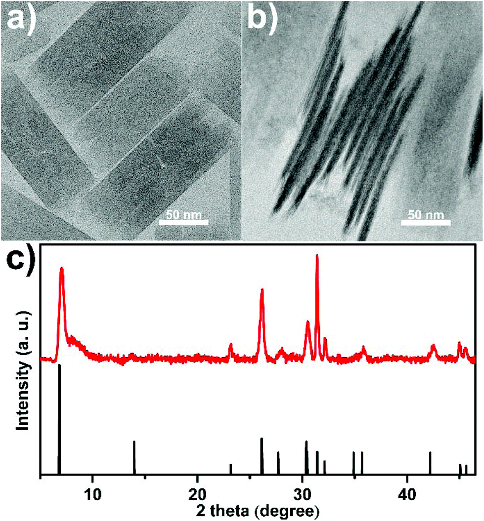 | ||
| Fig. 1 (a, b) TEM images and (c) XRD pattern of the as-synthesized CeO(CH3COO) ML nanoplates, the reference pattern in (c) is produced from ref. 41 and 52. | ||
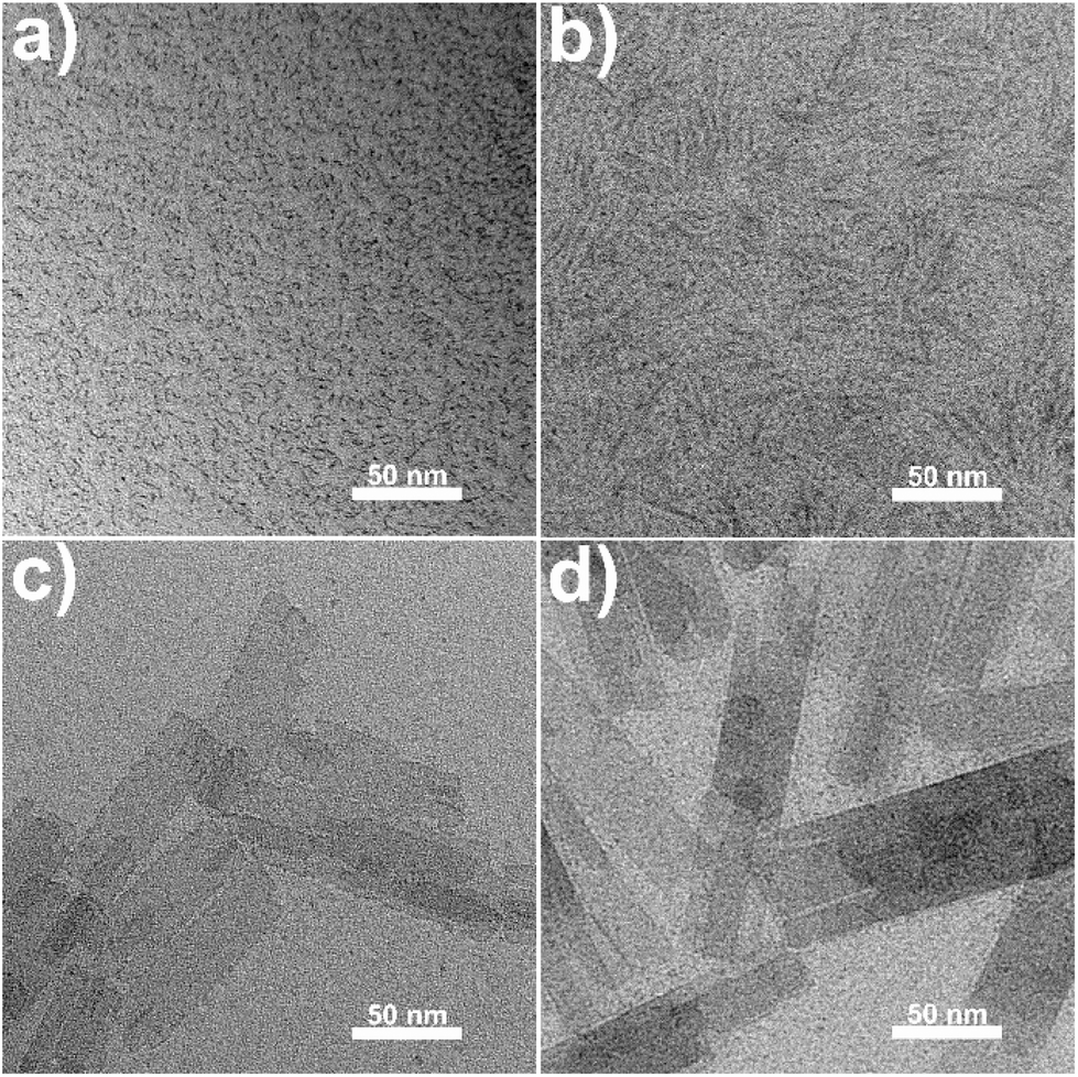 | ||
| Fig. 2 TEM images of products obtained at (a) 1 min, (b) 3 min, (c) 5 min and (d) 10 min after injection during the synthesis of CeO(CH3COO) ML nanoplates. | ||
During the synthesis of the CeO(CH3COO) nanoplates, when the CeO(CH3COO) SL nanoplates are formed, typically at 3 min after the injection, adding a mixture of 3 mmol OA and 9 mmol OAm into the reaction system will restrain the layer-by-layer growth and the as-synthesized CeO(CH3COO) SL nanoplates can transform into ceria SL nanoplates without elevating the reaction temperature (see the ESI† for details). TEM images of the as-synthesized ceria SL nanoplates are shown in Fig. 3. Fig. 3a shows that the SL nanoplates have a length of 177 ± 12 nm and a width of 17 ± 2 nm. Fig. 3b and the inset show that the SL nanoplates have a thickness of 1.1 ± 0.2 nm. The Fourier transform infrared (FT-IR) spectrum (Fig. S4a†) shows that the as-synthesized SL nanoplates are covered by oleate ions. The small-angle XRD (SAXRD) pattern (Fig. S4b†) of the SL nanoplates shows obvious (001) and (002) reflections at 2.9° and 5.4°, respectively, which indicates the arrangement of the nanoplates with a periodicity of 3.0 nm. These results fit well with the thickness of the nanoplates measured from TEM images as the length of 1.8 nm for oleate ions (Fig. S4b†). The selected area electron diffraction (SAED) pattern (inset in Fig. 3a) and high-resolution TEM (HRTEM) image (Fig. 3c), together with the XRD pattern (Fig. S5†), confirm that the SL nanoplates are ceria (JCPDS no. 04-0593) with a cubic fluorite structure. Due to the ultrathin nature of the ceria SL nanoplates, they are fragmentized under high-energy electron beam irradiation preventing the confirmation of the exposure facets of the SL nanoplates from the HRTEM image. Fig. 3d is taken at a much smaller magnification of 200k, and the fast Fourier transform (FFT) pattern (inset in Fig. 3d) of the selected area in Fig. 3d shows an array of spots which can be indexed to the {200} and {220} reflections of ceria. The FFT pattern clearly indicates that the SL nanoplates are single crystals, and enclosed with {100} facets.5
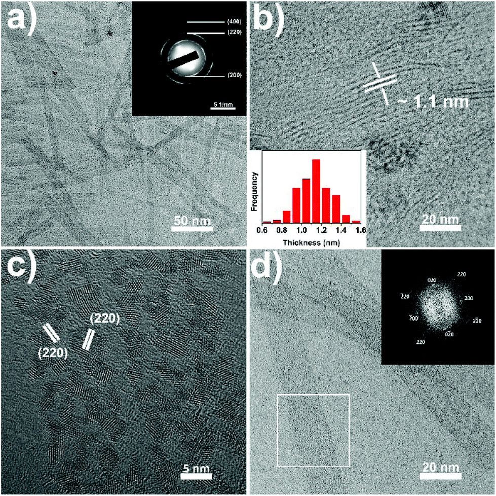 | ||
| Fig. 3 Characterization of the as-synthesized ceria SL-nanoplates. (a, b) TEM images; (c) HRTEM image; (d) TEM images; the inset in (a) is the SAED pattern of the ceria SL-nanoplates; the inset in (b) shows the thickness distribution of the SL-nanoplates; the inset in (d) is the FFT pattern of the selected area in (d). | ||
During the synthesis of CeO(CH3COO) nanoplates, when the ML nanoplates are formed, typically at 10 min after the injection, raising the reaction temperature to 380 °C will lead to the formation of ceria ML nanoplates with Ce2O2CO3 ML nanoplates as an intermediate (Fig. S6†) (see the ESI† for details). TEM images of ceria ML nanoplates are shown in Fig. 4. Fig. 4a and b (also see Fig. S7†) show that the as-synthesized ceria ML nanoplates have a 2D lamellar structure in which many ultrathin layers stack together. The high-angle annular dark-field scanning TEM (HAADF-STEM) image of the product (Fig. 4c) shows an obvious contrast difference in each nanoplate and further confirms the multi-layered structure. The ML nanoplates have a width of 46 ± 8 nm, a length of 166 ± 30 nm and a total thickness of 7 ± 2 nm. The XRD pattern of the ML nanoplates (Fig. S8†) can be well indexed to ceria (JCPDS no. 04-0593). The HRTEM image of the ceria ML nanoplates (Fig. 4d) shows an interplanar distance of 0.28 nm along both the long and short edges of the rectangular nanoplates, indicating that the four sides of the ceria ML nanoplates are all {100} facets. The SAED pattern (Fig. 4e) shows that ceria ML nanoplates are single crystals, and the zone axis is [001] which indicates that both the top and bottom surfaces of the nanoplates belong to the {100} facets. In the XRD pattern (Fig. S8†), the (200) peak is the strongest peak. The unusual high intensity indicates that the as-synthesized ceria ML nanoplates expose more (200) facets which is consistent with the HRTEM and SAED results. TEM images taken from the side of the ML nanoplates (Fig. 4f and S7†) show that the layers in the ML nanoplates have a thickness of 0.6 ± 0.1 nm, which is approximately the size of a single ceria unit cell (0.54 nm). The thickness is smaller than that of the SL nanoplates which can be explained by the multi-layered structure restraining the growth of the layers in the ML nanoplates.
 | ||
| Fig. 4 Characterization of the as-synthesized ceria ML-nanoplates. (a, b) TEM images; (c) HAADF-STEM image; (e) SAED pattern; (d, f) HRTEM images; the inset in (f) shows the thickness distribution of the layers in the ML nanoplates. | ||
From the above experiments, we could see that CeO(CH3COO) plays a critical role in the synthesis of ceria ML and SL nanoplates. As a pyrolysis intermediate of cerium acetate, it acts as the in situ formed self-sacrificed template for the preparation of ceria SL and ML nanoplates by the hot-injection pyrolysis method. With similar reaction conditions to the synthesis of their cerium counterpart (see the ESI† for details), the whole series of REO(CH3COO) ML nanoplates (Fig. S9†) are formed. Fig. S9† shows that the as-synthesized REO(CH3COO) nanoplates all adopt a ML plate-like morphology with a lateral size ranging from 100 nm to several microns. XRD results (Fig. S10†) show that they all crystallize in the same structure as CeO(CH3COO). By introducing extra OA and OAm into the reaction system, the whole series of RE2O3 SL nanoplates are formed (Fig. S11†). The RE2O3 SL nanoplates are rectangular from La2O3 to Eu2O3, and circular from Gd2O3 to Lu2O3 and Y2O3. XRD results (Fig. S12†) also show a similar transformation with the strongest peak transforming from (004) to (111). The HRTEM images of the SL Eu2O3, Gd2O3 and Y2O3 nanoplates in Fig. S13† show the exposed facets transformed from {004} to {111}.
In summary, we have constructed a self-sacrificed template method for the synthesis of the whole series of ultrathin rare earth oxide nanoplates with in situ formed REO(CH3COO) nanoplates that act as the template. The self-sacrificed template method is robust and general, and provides the foundation for further research on ultrathin rare earth oxide nanoplates.
Acknowledgements
This work was supported by the NSFC (No. 21425101, 21321001, 21371011, 21331001, and 91422302) and the MOST of china (2014CB643800).References
- K. S. Novoselov, A. K. Geim, S. V. Morozov, D. Jiang, Y. Zhang, S. V. Dubonos, I. V. Grigorieva and A. A. Firsov, Science, 2004, 306, 666–669 CrossRef CAS PubMed.
- K. J. Koski and Y. Cui, ACS Nano, 2013, 7, 3739–3744 CrossRef CAS PubMed.
- S. Z. Butler, S. M. Hollen, L. Y. Cao, Y. Cui, J. A. Gupta, H. R. Gutierrez, T. F. Heinz, S. S. Hong, J. X. Huang, A. F. Ismach, E. Johnston-Halperin, M. Kuno, V. V. Plashnitsa, R. D. Robinson, R. S. Ruoff, S. Salahuddin, J. Shan, L. Shi, M. G. Spencer, M. Terrones, W. Windl and J. E. Goldberger, ACS Nano, 2013, 7, 2898–2926 CrossRef CAS PubMed.
- X. Zhang and Y. Xie, Chem. Soc. Rev., 2013, 42, 8187–8199 RSC.
- Y. Guo, K. Xu, C. Wu, J. Zhao and Y. Xie, Chem. Soc. Rev., 2015, 44, 637–646 RSC.
- M. Chhowalla, H. S. Shin, G. Eda, L. J. Li, K. P. Loh and H. Zhang, Nat. Chem., 2013, 5, 263–275 CrossRef PubMed.
- C. Tan and H. Zhang, Nat. Commun., 2015, 6, 7873 CrossRef CAS PubMed.
- S. Hu and X. Wang, Chem. Soc. Rev., 2013, 42, 5577–5594 RSC.
- H. Zhang, ACS Nano, 2015, 9, 9451–9469 CrossRef CAS PubMed.
- C. Tan and H. Zhang, Chem. Soc. Rev., 2015, 44, 2713–2731 RSC.
- H. X. Mai, L. D. Sun, Y. W. Zhang, R. Si, W. Feng, H. P. Zhang, H. C. Liu and C. H. Yan, J. Phys. Chem. B, 2005, 109, 24380–24385 CrossRef CAS PubMed.
- Q. Dai, S. Bai, H. Li, W. Liu, X. Wang and G. Lu, CrystEngComm, 2014, 16, 9817–9827 RSC.
- Q. Dai, W. Wang, X. Wang and G. Lu, Appl. Catal., B, 2017, 203, 31–42 CrossRef CAS.
- W. Bi, M. Zhou, Z. Ma, H. Zhang, J. Yu and Y. Xie, Chem. Commun., 2012, 48, 9162–9164 RSC.
- Y. Sun, Q. Liu, S. Gao, H. Cheng, F. Lei, Z. Sun, Y. Jiang, H. Su, S. Wei and Y. Xie, Nat. Commun., 2013, 4, 2899 Search PubMed.
- F. Lei, Y. Sun, K. Liu, S. Gao, L. Liang, B. Pan and Y. Xie, J. Am. Chem. Soc., 2014, 136, 6826–6829 CrossRef CAS PubMed.
- X. J. Wu, X. Huang, X. Qi, H. Li, B. Li and H. Zhang, Angew. Chem., Int. Ed., 2014, 53, 8929–8933 CrossRef CAS PubMed.
- X. J. Wu, X. Huang, J. Liu, H. Li, J. Yang, B. Li, W. Huang and H. Zhang, Angew. Chem., Int. Ed., 2014, 53, 5083–5087 CAS.
- Y. Zhu, C. Cao, T. Shi, W. Chu, Z. Wu and Y. Li, Sci. Rep., 2014, 4, 5787–5787 CAS.
- D. Wang, Y. Kang, V. Doan-Nguyen, J. Chen, R. Küngas, N. L. Wieder, K. Bakhmutsky, R. J. Gorte and C. B. Murray, Angew. Chem., Int. Ed., 2011, 50, 4378–4381 CrossRef CAS PubMed.
- D. Wang, Y. Kang, X. Ye and C. B. Murray, Chem. Mater., 2014, 26, 6328–6332 CrossRef CAS.
- D. Hudry, A. M. M. Abeykoon, J. Hoy, M. Y. Sfeir, E. A. Stach and J. H. Dickerson, Chem. Mater., 2015, 27, 965–974 CrossRef CAS.
- Q. Zhang and B. Yan, Chem – Eur. J., 2012, 18, 5150–5154 CrossRef CAS PubMed.
- T. Paik, T. R. Gordon, A. M. Prantner, H. Yun and C. B. Murray, ACS Nano, 2013, 7, 2850–2859 CrossRef CAS PubMed.
- Y. C. Cao, J. Am. Chem. Soc., 2004, 126, 7456–7457 CrossRef CAS PubMed.
- R. Si, Y. W. Zhang, L. P. You and C. H. Yan, Angew. Chem., Int. Ed., 2005, 44, 3256–3260 CrossRef CAS PubMed.
- R. Si, Y. W. Zhang, H. P. Zhou, L. D. Sun and C. H. Yan, Chem. Mater., 2006, 19, 18–27 CrossRef.
- T. Yu, J. Joo, Y. I. Park and T. Hyeon, J. Am. Chem. Soc., 2006, 128, 1786–1787 CrossRef CAS PubMed.
- J. Jeong, N. Kim, M. G. Kim and W. Kim, Chem. Mater., 2016, 28, 172–179 CrossRef CAS.
- Z. Huo, C. K. Tsung, W. Huang, M. Fardy, R. Yan, X. Zhang, Y. Li and P. Yang, Nano Lett., 2009, 9, 1260–1264 CrossRef CAS PubMed.
- S. Hu, H. Liu, P. Wang and X. Wang, J. Am. Chem. Soc., 2013, 135, 11115–11124 CrossRef CAS PubMed.
- H. Imagawa and S. Sun, J. Phys. Chem. C, 2012, 116, 2761–2765 CAS.
- X. Zhang, J. Ge, Y. Xue, B. Lei, D. Yan, N. Li, Z. Liu, Y. Du and R. Cai, Chem – Eur. J., 2015, 21, 11954–11960 CrossRef CAS PubMed.
- X. Y. Zhang, Y. W. Wang, F. H. Cheng, Z. P. Zheng and Y. P. Du, Sci. Bull., 2016, 18, 1422–1434 CrossRef.
- J. Höls, M. Lahtinen, M. Lastusaari, J. Valkonen and J. Viljanen, J. Solid State Chem., 2002, 165, 48–55 CrossRef.
- R. P. Turcotte, J. O. Sawyer and L. R. Eyring, Inorg. Chem., 1969, 8, 238–246 CrossRef CAS.
- H. Hülsing, H. G. Kahle, M. Schwab and H. J. Schwarzbauer, J. Magn. Magn. Mater., 1978, 9, 68–70 CrossRef.
- D. Yan, B. Lei, X. J. Wu, Z. Q. Liu, N. Li, J. Ge, Y. M. Xue, Y. P. Du, Z. P. Zheng and H. Zhang, Appl. Mater. Today, 2015, 1, 20–26 CrossRef.
- L. Zhang, D. Jiang, J. Xia, C. Li, N. Zhang and Q. Li, RSC Adv., 2014, 4, 17648–17652 RSC.
- M. Inoue, H. Kominami, H. Otsu and T. Inui, Nippon Kagaku kaishi, 1991, 1991, 1254–1260 CrossRef.
- H. Kominami, M. Inoue and T. Inui, Nippon Kagaku kaishi, 1993, 1993, 605–611 CrossRef.
- S. Hosokawa, S. Iwamoto and M. Inoue, Mater. Res. Bull., 2008, 43, 3140–3148 CrossRef CAS.
- S. Hosokawa, K. Shimamura and M. Inoue, Mater. Res. Bull., 2011, 46, 1928–1932 CrossRef CAS.
- K. Manabe, M. Ogawa and Y. Eizuka, Nippon Kagaku kaishi, 1983, 461–463 Search PubMed.
- K. Manabe and M. Ogawa, Nippon Kagaku kaishi, 1979, 1013–1019 CrossRef CAS.
- M. Ogawa and K. Manabe, Nippon Kagaku kaishi, 1993, 600–604 CrossRef CAS.
- M. Ogawa and K. Manabe, J. Ceram. Soc. Jpn., 1988, 96, 890–893 CrossRef CAS.
- K. Manabe and M. Ogawa, Nippon Kagaku kaishi, 1982, 694–696 CrossRef CAS.
- M. Ogawa and K. Manabe, J. Ceram. Soc. Jpn., 1988, 96, 672–676 CrossRef CAS.
- T. Arii, A. Kishi, M. Ogawa and Y. Sawada, Anal. Sci., 2001, 17, 875–880 CrossRef CAS.
- T. Arii, T. Taguchi, A. Kishi, M. Ogawa and Y. Sawada, J. Eur. Ceram. Soc., 2002, 22, 2283–2289 CrossRef CAS.
- K. Manabe and M. Ogawa, Nippon Kagaku kaishi, 1983, 1983, 1092–1095 CrossRef.
Footnote |
| † Electronic supplementary information (ESI) available: Synthesis details and supplementary figures. See DOI: 10.1039/c7qi00201g |
| This journal is © the Partner Organisations 2017 |