 Open Access Article
Creative Commons Attribution 3.0 Unported Licence
Topological landscapes of porous organic cages†
Valentina
Santolini
,
Marcin
Miklitz
 ,
Enrico
Berardo
 and
Kim E.
Jelfs
 *
*
Department of Chemistry, Imperial College London, South Kensington, London, SW7 2AZ, UK. E-mail: k.jelfs@imperial.ac.uk; www.twitter.com/JelfsChem; Tel: +44 (0)20759 43438
First published on 16th March 2017
Abstract
We define a nomenclature for the classification of porous organic cage molecules, enumerating the 20 most probable topologies, 12 of which have been synthetically realised to date. We then discuss the computational challenges encountered when trying to predict the most likely topological outcomes from dynamic covalent chemistry (DCC) reactions of organic building blocks. This allows us to explore the extent to which comparing the internal energies of possible reaction outcomes is successful in predicting the topology for a series of 10 different building block combinations.
Introduction
Molecular design is the perpetual ambition of chemists as they strive for more complex and unusual molecular assemblies, both for their inherent beauty and to encode more sophisticated functions. These assemblies include both network materials, such as metal–organic frameworks (MOFs), and discrete molecular architectures that are of the nanometre scale. For network materials, the enumeration of possible framework topologies1–4 has allowed for the targeting of topologies through the design of ligands and nodes that meet the necessary geometric requirements. This “reticular design” has assisted in the synthetic realisation of >91 different MOF topologies,5 from a potential of >2500.4 However, although reticular design has achieved many notable successes, such as the series of IRMOFs with a cubic-based topology of increasing ligand length,6 too often the topological outcome of a synthesis remains a matter of serendipity, rather than successful a priori design.For finite molecular hosts, a wide range of different motifs have been realised, including rings, cycles, knots, polyhedra and catenanes.7–9 Here we focus upon molecular cage compounds, defined by IUPAC as polycyclic compounds with the shape of a cage. These have the potential to host other molecules inside their internal cavity, but, unlike macrocycles, also have three dimensional structures with multiple possible entry and exit routes through molecular windows. Organic molecular cages have been of increasing research interest in recent years,9–13 although they have a longer history, including a range of cryptands,14 carcerands,15,16 and capsule-like molecules. Potential applications for these molecular hosts include encapsulation,17 catalysis,18 molecular separations of organic molecules19,20 or gases,21,22 molecular sensing,23,24 molecular reaction vessels, or as porous liquids.25
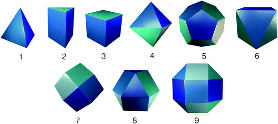
Whilst framework materials can be related to underlying extended network topologies, the equivalent topologies for molecular materials include, but are not limited to, polyhedra such as Platonic and Archimedean solids, see Fig. 1. Throughout this work, we use the term topology to refer to the underlying connectivity of molecular building blocks (BBs) in the molecular cage, which is unchanged upon any physical deformation. Whilst initially capsule-like topologies (with two end groups such as cavitands connected by multiple ditopic ligands to form a cavity) dominated, in the last decade a broader range of topologies have been synthetically realised. These polyhedra include tetrahedra, cubes, octahedra, square antiprisms and cuboctahedra, although capsules, tetrahedra and cubes are most commonly observed. A molecule with a single topology could adopt multiple different geometrical shapes, dependent upon factors such as the geometry of the component BBs and their conformational flexibility. For example, as shown in Fig. 2, a molecule with an underlying tetrahedral topology could have the approximate geometrical shape of a tetrahedron or an octahedron, or related intermediate shapes, dependent upon the component BBs.
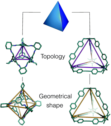 | ||
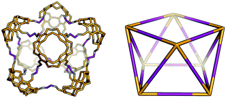
| Fig. 2 An example of how two porous organic cages that both have an underlying topology of a tetrahedron adopt different geometric shapes, in one case maintaining a tetrahedron shape26 (right hand side), and in the other adopting an octahedral shape (left hand side).27 The underlying topologies are shown in purple and the geometric shapes in orange. Hydrogen atoms and multiple bonds are omitted for clarity throughout the text. | ||
The growing interest in the field of organic cage molecules makes it timely to identify the potential topological possibilities for these materials and to establish a uniform classification system for them. As stated by Brunner in 1981, the “synthesis of new structures requires not only chemical skill but also some knowledge of the principal topological possibilities”.28 Hay has recently discussed design principles for metal–organic polygons and polyhedra (MOPs), emphasising that referring to these molecules by their shape can lead to multiple classifications for the same underlying topology, particularly for polyhedra that are face-directed, dependent on how you relate the metals and ligands to the vertices, edges or faces.29 Instead, Hay proposes a nomenclature based upon the number of vertices, edges or faces involved in the MOP and its point group. We agree with this approach, and here lay out an extension of this nomenclature for wholly organic molecules.
We then examine which topologies have been synthetically reported and choose a set of molecules from each topological family described to computationally investigate the underlying factors that influence the observed topological forms. Firstly however, in the following section we discuss the factors that can influence the topology formed for a porous organic cage.
Topological control?
Currently, the ‘design’ of a particular topology in a new porous cage system is possible for fairly rigid BBs, although is not always successful, as there can be unexpected outcomes. There are examples of BBs designed to meet the appropriate geometrical requirements for, for example, forming a molecular cube in an [8 + 12] reaction of eight corner units (with angles of ∼90°) and 12 linear struts for the edge,30,31 or forming a cuboctahedron via molecular panelling of tritopic and tetratopic BBs.32 More commonly, once a particular polyhedral cage has been made, a family of related polyhedra can be synthesised via small variations in the functionality of one or the other of the BBs. However, even this can fail, for example we reported a change from a cyclohexane diamine to a cyclopentane diamine resulting in a larger [8 + 12] molecule, with an underlying topology of a cube, forming in place of a [4 + 6] molecule.33 Worse still, whilst the [4 + 6] molecule formed a porous solid state material, with a BET surface area of >1300 m2 g−1, the [8 + 12] molecule was found to lack shape persistence in the absence of a solvent and hence to form an amorphous, non-porous material. Thus, a very subtle difference in the reaction precursors had an enormous effect on the reaction outcome and therefore properties of the molecular cage material. Fujita describes this type of phenomenon as “emergent behaviour”34 and it is clear that this can also thwart attempts at the topological design of organic cage materials. Further complicating the matter, there are some reports of the kinetic trapping of products26 or of solvent choice influencing the topological outcome; in an example from Liu and Warmuth, where they reacted a tetraformylcavitand with ethylene diamine in an imine condensation reaction, it was found that changing between tetrahydrofuran, chloroform and dichloromethane as the solvent could change the dominant product from a [4 + 8] cage, to a [6 + 12] octahedron to a [8 + 16] square antiprism.35As the majority of organic cages are formed by reversible dynamic covalent chemistry (DCC), the product distribution should be thermodynamically controlled, with those molecules with the lowest free energy being the dominant reaction product. Of course, this depends upon the reaction mixture being able to afford this product, rather than being kinetically trapped into alternative products, which is known to have happened with alkyne metathesis formed cages26 and for 2D imine molecular ladders,36 and may become more common as the number of bond formation reactions in a structure increases. Alternative products could include a range of different size oligomeric products, a polymeric material, alternative molecules with different topologies, or catenated molecules. Whilst reports of catenanes for porous organic cages are so far rare, examples from Hasell et al.37 and Zhang et al.38 suggest that in some cases catenanes can be the thermodynamic product, rather than their monomeric equivalent, as a result of ‘self-templating’ driven by the introduction of intermolecular interactions such as π–π stacking and alkyl–π interactions in the catenated form. In general, it is likely that, dependent on after how much time the product is isolated and characterised, different products might be observed as the mixture evolves. Whilst many organic cage molecules have been isolated in high yield (up to 100%),39 there are reports of systems where a mixture of products has been isolated from a single solution,35 presumably a greater driving force for a single topology being required for isolation of a single product.
We now consider factors that can influence the topological energy landscape and thus the likely topology and shape of the organic cage molecules formed for a set of BBs.
Number of reactive end groups
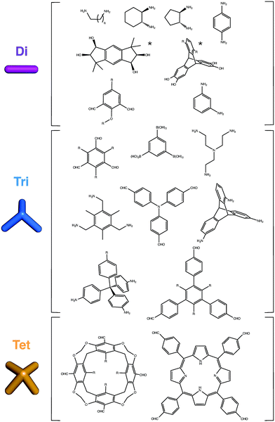
Although two BBs that are ditopic can only form single cycles, larger numbers of end groups can form more complex, polycyclic topologies. Examples of common BBs used in the synthesis of organic cage molecules thus far are shown in Fig. 3. For organic BBs, where high symmetry is typically sought in the BBs, at least with a Cn symmetry axis with n equal to the number of reactive end groups, there are fewer options as n increases. This distinguishes organic cage molecules from MOPs, where higher coordination numbers at metal sites may be more easily accessed.Stoichiometry of building blocks
The component BBs need to be combined in the correct stoichiometric ratio to access the targeted topology, for example a cube with 8 tritopic vertex BBs and 12 ditopic edge BBs is formed from a 2![[thin space (1/6-em)]](https://www.rsc.org/images/entities/char_2009.gif) :
:![[thin space (1/6-em)]](https://www.rsc.org/images/entities/char_2009.gif) 3 reactant ratio. Providing an excess of one BB has been known to skew the topological landscape towards alternative products, where not all of the reactive end groups have formed covalent bonds.32
3 reactant ratio. Providing an excess of one BB has been known to skew the topological landscape towards alternative products, where not all of the reactive end groups have formed covalent bonds.32
Building block geometry and rigidity
The geometry of the BB and the arrangement and direction of the reactive end groups can play a vital role in forming a desired topology. The angle between the reactive end groups and the centre of at least one of the BBs must obviously be less than 180° for a chance of making a finite molecular, rather than periodic, structure. If one wanted to synthesise a molecule with a cubic shape and underlying cubic topology, then we might consider that we want tritopic ligands with (end group)–(centre of mass)–(end group) angles of 90° to form a corner and ditopic ligands of (end group)–(centre of mass)–(end group) angles of 180° to form the edges. Indeed, this approach has been successful for the design of the two molecular cubes reported thus far from both the Warmuth30 and Beuerle31 groups. For MOPs, it was reported that the angles need not be perfectly matched to the desired topology, with deviations of <10° likely to be tolerated, and even larger deviations often able to be compensated by the summation of small adaptions from other BBs, although significant deviations can lead to structures with shapes more severely distorted from the base topological shape.40 For MOPs, design rules for both the topology and shape design through complementary end group vector selection in the BBs have been proposed,8,40 however, recent analysis of the crystal structures of MOPs by Young and Hay found that whilst sometimes this approach works, it does not do so in the majority of cases.29 These failures were due to either deviation from the ideal bonding vector through conformational flexibility or, more often, due to a concerted rotation about symmetry axes in the molecule.29If the lack of rigidity in MOP assemblies frustrates the simple geometric design of BBs, then this is even more problematic for organic cages that have less strongly directional bonding. In the successful cases of geometric BB design thus far, rigidity of the underlying BBs has assisted in this design simplification. However, rigidity of the precursors is not a requirement for an organic cage assembly and with many functions of these materials, such as the host–guest response behaviour, often relying on dynamic motion of the final assembly, we conclude that it is important not to rule out more flexible BBs as potential cage components. This does however significantly increase the design challenge, and we believe necessitates the application of computational modelling in order to predict the conformations of the resultant assemblies. Of course ‘rigidity’ and ‘flexibility’ are not absolutes; whilst some flexibility and motion of a component is inevitable, excessive flexibility in the linkers is linked to lower product yields9 and increases the likelihood that the end assembly will not be shape persistent.
Entropy
Following the second law of thermodynamics, every spontaneous process is associated with an increase in symmetry (dynamic or static) of the original system.41 The entropy of symmetry can play a role in favouring structures with a higher symmetry, for example disfavouring linear oligomers over high symmetry structures, such as the symmetric topologies based on Platonic or Archimedean solids discussed here. The entropy of symmetry can be correlated to the symmetry number (σ)42,43 and as previously reported by Skowronek et al.,44 these contributions range from 3–8 kJ mol−1 from a C3 to D3 to Td to Oh symmetry molecule. Whilst significant in driving the formation of symmetric finite molecules, it is however unlikely that these contributions would influence which molecular topology is formed. Likely, more energetically significant is that entropy can be expected to disfavour large molecules over the alternative outcome of multiple smaller assemblies. Thus, to synthesise large architectures, a significant driving force is required.Solvent
The non-covalent interactions between solvent molecules and cages can alter both the thermodynamics and the kinetics of the cage formation process, potentially favouring the selective synthesis of a specific product.45,46 Poor solubility of reaction intermediates could result in low-yielding synthesis or precipitation during the assembly process.47 Warmuth and co-workers propose that the major contribution from solvent effects is played by the improper solvation of flexible BBs.35 Solvent molecules enclosed in a cavity tend to interact with the capsule's internal surface for a prolonged time (e.g. from 10−3 to 103 s), having enough time to establish a strong interaction with the BBs.45 During this process, solvent molecules located in the inner cavity and in the large windows will favour specific geometrical conformations of the BBs, preferentially driving the assembly towards a specific topology. The complex role of solvent effects on cage formation can therefore be summarised as depending on three main factors: (a) the entropic cost associated with molecular reorganisation by collecting the n BBs from the solvent phase; (b) the energetics of BB–solvent interactions (e.g. hydrophobic effects) and (c) the amount of strain felt by the BB within the final assembled system. Due to the complex and very variable character of solvent effects, these interactions are very hard to quantify and predict. In the work of Warmuth and co-workers, the differences in solvent effects estimated to explain the yields observed for different imine cage topologies in different solvents amounted to around ∼17 kJ mol−1 per imine bond.Synthesis method
The majority of organic cage molecules have been synthesised with batch chemistry at high dilution and slow addition, however recently cage molecules have also been synthesised through a continuous flow methodology.48,49 With the flow methodology, very short reaction times with less solvent were achieved, but with high purity and yield. These approaches and novel synthesis methods such as mechanochemistry50 may also provide alternative synthesis routes to different topologies because they influence the kinetics of the reaction and the reaction pathways.Other synthesis variables
These variables include the reaction temperature, concentration, rate of mixing, order of addition of precursors, use of catalysts, pH and template molecules.Enumeration of organic cage topologies
In our enumeration of possible organic cage topologies, we restrict ourselves to the following criteria: (i) the topology must be a polycyclic cage molecule, with the potential for a 3D internal cavity, excluding macrocycles such as cyclodextrins, crown ethers, cucurbiturils and 2D topologies that are polygons such as triangles, squares, pentagons etc.; (ii) it must be possible to form the topology from a two-component reaction of BBs through DCC; (iii) combinations of components that are ditopic, tritopic and tetratopic only; (iv) we presume that the BBs have a Cn symmetry axis with n equal to the number of reactive end groups and (v) for topologies with larger numbers of BBs, we include only higher symmetry structures that are relatable to Platonic or Archimedean solids that have been reported for MOPs, such that they are more feasible targets for organic cage molecules.These criteria, whilst not producing an exhaustive set of possible topologies, result in 20 topologies that are the most plausible organic cage structures and indeed, almost two-thirds have already been synthetically reported. Recently, mathematicians have developed an algorithm for generating maps of ‘stable planar cages’, where they did not restrict themselves to 2-component systems and generated >400![[thin space (1/6-em)]](https://www.rsc.org/images/entities/char_2009.gif) 000 unique maps.51 The majority of these maps are too complex to be feasible with organic chemistry and thus our limited number of plausible topologies is more practical. However, the topologies we discuss can still be used to describe the underlying connectivity in a multicomponent system and indeed, multiple components may be an attractive design approach for the synthesis of some of the lower symmetry topologies. Several examples of multiple component systems,52–55 including those with orthogonal DCC formation reactions, for example both boronate and imine formation,50,56 have been reported.
000 unique maps.51 The majority of these maps are too complex to be feasible with organic chemistry and thus our limited number of plausible topologies is more practical. However, the topologies we discuss can still be used to describe the underlying connectivity in a multicomponent system and indeed, multiple components may be an attractive design approach for the synthesis of some of the lower symmetry topologies. Several examples of multiple component systems,52–55 including those with orthogonal DCC formation reactions, for example both boronate and imine formation,50,56 have been reported.
For our discussion of organic cage topologies, we introduce a new nomenclature, labelling each structure as:
| XmpYn |
We will now discuss each of the topologies within the four families that consist of combinations of different connectivity BBs. The topologies and their features are summarised in Table 1 and experimentally reported topologies in Table 2.
| Topology | Edge-directed form | Face-directed form | Solid type | Multiple connections | Point group in high symmetry form | Ring sizes |
|---|---|---|---|---|---|---|
| Tri 2 Di 3 | 1 triple | D 3h | 43 | |||
| Tri 4 Di 6 | Tetrahedron | Platonic | T d | 64 | ||
| Tri 42 Di 6 | 2 double | D 2h | 42, 82 | |||
| Tri 6 Di 9 | Triangular prism | D 3h | 62, 83 | |||
| Tri 8 Di 12 | Cube | Platonic | O h | 86 | ||
| Tri 20 Di 30 | Dodecahedron | Platonic | I h | 1012 | ||
| Tet 2 Di 4 | 1 quadruple | D 4h | 44 | |||
| Tet 33 Di 6 | 3 double | D 3h | 43, 62 | |||
| Tet 42 Di 8 | 2 double | C 2v | 42, 64 | |||
| Tet 44 Di 8 | 4 double | D 4h | 44, 82 | |||
| Tet 55 Di 10 | 5 double | D 5h | 45, 102 | |||
| Tet 6 Di 12 | Octahedron | Platonic | O h | 68 | ||
| Tet 8 Di 16 | Square antiprism | D 4d | 68, 82 | |||
| Tet 16 Di 32 | Cuboctahedron | Archimedean | O h | 68, 86 | ||
| Tet 24 Di 48 | Rhombicuboctahedron | Archimedean | O h | 68, 818 | ||
| Tri 1 Tri 1 | C 3v | 23 | ||||
| Tri 22 Tri 2 | 2 double | D 2h | 22, 42 | |||
| Tri 32 Tri 3 | 2 double | C 1 | 22, 44 | |||
| Tri 4 Tri 4 | Tetrahedron | Platonic | T d | 46 | ||
| Tet 6 Tri 8 | Rhombic-dodecahedron | Catalan | O h | 412 | ||
| Topology | Reported? | CSD reference codes for crystal structures of archetypal examples |
|---|---|---|
| a This topology has been reported for a single component alkene metathesis reaction.69 b This topology has been reported with a bifunctional ditopic ligand and a cyclisation reaction. | ||
| Tri 2 Di 3 | Yes | ZUYPUG,57 AJOHUD,58 SATJAA59 |
| Tri 4 Di 6 | Yes | PUDXES,27 TOVWUY,60 EKUKUR61 |
| Tri 42 Di 6 | Noa | — |
| Tri 6 Di 9 | No | — |
| Tri 8 Di 12 | Yes | KATJAS,33 REYMAL,44 ZIRCIO62 |
| Tri 20 Di 30 | No | — |
| Tet 2 Di 4 | Yes | LUXVAB63 |
| Tet 33 Di 6 | Yes | VILCEZ64![[thin space (1/6-em)]](https://www.rsc.org/images/entities/char_2009.gif) b b |
| Tet 42 Di 8 | Yes | No reported crystal structures35 |
| Tet 44 Di 8 | Yes | AVAFIN65 |
| Tet 55 Di 10 | No | — |
| Tet 6 Di 12 | Yes | No reported crystal structures35 |
| Tet 8 Di 16 | Yes | No reported crystal structures35 |
| Tet 16 Di 32 | No | |
| Tet 24 Di 48 | No | |
| Tri 1 Tri 1 | Yes | No reported crystal structures66 |
| Tri 22 Tri 2 | No | — |
| Tri 32 Tri 3 | No | — |
| Tri 4 Tri 4 | Yes | VOFROZ67 |
| Tet 6 Tri 8 | Yes | QUFYIB, QUFYOH68 |
Tritopic + ditopic topology family
Tritopic and ditopic BBs can be combined in a 2![[thin space (1/6-em)]](https://www.rsc.org/images/entities/char_2009.gif) :
:![[thin space (1/6-em)]](https://www.rsc.org/images/entities/char_2009.gif) 3 ratio to form molecular cages. The smallest topology for this family is the capsular Tri2Di3 topology formed from a [2 + 3] reaction of two tritopic BBs linked to three ditopic BBs, as shown in Fig. 4, where all the topologies of this family are reported. There are multiple synthetic reports of this topology; example references, including reference codes for structures in the Cambridge Structural Database (CSD) are given in Table 2, these cages have reported functions in gas separation70 and sensing.24 This structure can have an intrinsic, shape-persistent cavity if the BBs are relatively rigid and has three cycles which form windows to access the central cavity; all these have a ring size of 4 (where 4 is the number of BBs that constitute the ring).
3 ratio to form molecular cages. The smallest topology for this family is the capsular Tri2Di3 topology formed from a [2 + 3] reaction of two tritopic BBs linked to three ditopic BBs, as shown in Fig. 4, where all the topologies of this family are reported. There are multiple synthetic reports of this topology; example references, including reference codes for structures in the Cambridge Structural Database (CSD) are given in Table 2, these cages have reported functions in gas separation70 and sensing.24 This structure can have an intrinsic, shape-persistent cavity if the BBs are relatively rigid and has three cycles which form windows to access the central cavity; all these have a ring size of 4 (where 4 is the number of BBs that constitute the ring).
 | ||
| Fig. 4 The tritopic + ditopic topology family. Tritopic vertices are in blue, ditopic linkers in purple. | ||
The Tri4Di6 topology is formed from a [4 + 6] reaction and is related to a tetrahedron via an edge-directed assembly, with the tritopic BB placed on each of the vertices of the tetrahedron and the ditopic BB along the edges. The topology has four potential access windows and all these have a ring size of 6. Again, this is a very commonly reported topology in the literature, including systems from Cooper and co-workers27 for molecular separations19,20,22 and as porous liquids,25 and from Mastalerz and co-workers for sensing.23
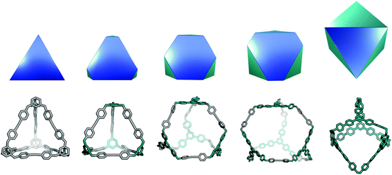
This topology has also been reported for CC1 (Covalent Cage 1), CC2, and CC4 molecules in a triply-interlocked catenated form, which we label c-Tri4Di6.37 A molecule with a Tri4Di6 topology, if shape-persistent, can adopt final shapes ranging anywhere between a tetrahedron at one extreme to an octahedron at the opposite extreme. Reported examples of the Tri4Di6 topology molecules with these shapes are also shown in Fig. 2. For a tetrahedral shape to form, the tritopic BB could adopt a conformation to act as a capping vertex, with (end group)–(centre of mass)–(end group) angles of ∼60°, and the ditopic BB being linear. For an octahedral shape, the tritopic BB could be planar with (end group)–(centre of mass)–(end group) angles of ∼120° and the ditopic BB bent with an angle of ∼60°. With consideration of conformational flexibility in the BBs of organic cages, these geometric requirements are not essential, as compensation in each of the BBs could still achieve a given shape. The transformation of a tetrahedral shape to an octahedral shape occurs through a process of truncation of the tetrahedron's vertices. In Fig. 6, we show this transformation alongside a series of hypothetical porous organic cages of the Tri4Di6 topology, whose changing BBs show one way in which this range of shapes could be accessed. From an initial molecule with both the shape and topology of a tetrahedron, one can cause “flattening” of the corners of the molecule by swapping the starting tritopic BB with a planar tritopic precursor. Then, increasing the size of the planar tritopic BBs can lead to geometric shapes with higher degrees of truncation. Finally, an octahedral geometric shape is obtained by increasing the “bending” of the linear ditopic precursor. The key point is that all these molecules have a tetrahedral topology, despite adopting different geometrical shapes (refer to Fig. 2).
 | ||
| Fig. 5 The tetratopic + ditopic topology family. Tetratopic vertices are in orange, ditopic linkers in purple. | ||
The Tri42Di6 topology is also formed from a [4 + 6] reaction, but it contains two doubly connected tritopic BBs as well as two singularly connected BBs. The double connections result in two distinct window sizes, two rings of size 4 and two rings of size 8. This topology has not yet been reported for a DCC reaction, however, in 2014 Wang et al. reported the synthesis of this topology via a one-component alkene metathesis reaction.69 The component BB has a C3 symmetry axis and therefore reduced symmetry in the BB need not necessarily be employed to reach this topology if BB flexibility can account for this. This topology should be achievable through two-component DCC reactions.
The Tri6Di9 topology is formed from a [6 + 9] reaction and is related to a triangular prism via an edge-directed assembly and has five potential access windows, two with ring size 6 and three with ring size 8. We do not believe this topology has been synthetically reported, it will require tritopic BBs that have two (end group)–(centre of mass)–(end group) angles of 90° and one of 60°, to form both triangular and square connectivity rings, or BBs that can compensate for the differing angles required. This topology may be more easily achieved with lower symmetry BBs.
The Tri8Di12 topology is formed from a [8 + 12] reaction and is related to a cube via an edge-directed assembly and has 6 potential access windows, all with ring size 8. Multiple examples of this topology have been synthetically reported, although several lack shape-persistence. A catenated form of this topology, c-Tri8Di12 has been reported by Zhang et al.38 This molecule can adopt final geometric shapes ranging from a cube to the opposite extreme of a shape formed from planar tritopic BBs; reported examples of Tri8Di12 topology molecules with these shapes are shown in Fig. 7. For a cubic shape to form, the tritopic BB could adopt a conformation to act as a capping vertex, with (end group)–(centre of mass)–(end group) angles of ∼90°, and the ditopic BB would then be linear. For the vertex-folded shape, the tritopic BB could be more planar with (end group)–(centre of mass)–(end group) angles of ∼120° and the ditopic BB bent.
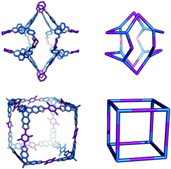 | ||
| Fig. 7 The range of geometric shapes possible for Tri8Di12 topology cages, from a vertex-folded shape71 (top), to a cube31 (bottom). | ||
The final topology that we suggest for this family is a Tri20Di30 molecule from a [20 + 30] reaction and is related to a dodecahedron via an edge-directed assembly and has twelve potential access windows, all with ring size 10. This topology has not been reported for an organic cage molecule, although it has been reported for a MOP.72 It remains an alluring synthetic target, albeit very challenging due to potential issues with the solubility of the intermediates and the need to have a thermodynamic driving force for a dodecahedron over other topologies or an infinite polymeric product. Furthermore, it will be particularly challenging for this large molecule to be shape-persistent. The most obvious way to design this topology is to have an (end group)–(centre of mass)–(end group) angle of ∼108° in the tritopic BB, to match that of a dodecahedron's vertices, and to combine this with a linear ditopic BB. The required angle of ∼108° is close to that of a tetrahedral carbon, thus tri-functionalised methane molecules, such as those used by Olenyuk et al. for the synthesis of the dodecahedral MOP,72 are plausible BBs.
Tetratopic + ditopic topology family
Tetratopic and ditopic BBs can be combined in a 2![[thin space (1/6-em)]](https://www.rsc.org/images/entities/char_2009.gif) :
:![[thin space (1/6-em)]](https://www.rsc.org/images/entities/char_2009.gif) 4 ratio to form molecular cages. The smallest topology in this family is the capsular Tet2Di4 topology, formed from a [2 + 4] reaction of two tetratopic end groups linked with three ditopic linkers, as shown in Fig. 5, where all the topologies of this family are reported. The topology has four windows of ring size 4. There are multiple synthetic reports of this topology (see Table 2) and the topology can have an intrinsic, shape-persistent cavity if the BBs are relatively rigid.
4 ratio to form molecular cages. The smallest topology in this family is the capsular Tet2Di4 topology, formed from a [2 + 4] reaction of two tetratopic end groups linked with three ditopic linkers, as shown in Fig. 5, where all the topologies of this family are reported. The topology has four windows of ring size 4. There are multiple synthetic reports of this topology (see Table 2) and the topology can have an intrinsic, shape-persistent cavity if the BBs are relatively rigid.
The Tet33Di6 topology is formed from a [3 + 6] reaction, containing three sets of doubly connected tetratopic BBs, so all have the same connectivity environment. The double connections result in two distinct window sizes, three rings of size 4 and two rings of size 6. This topology has been reported using a bifunctional ditopic ligand with a cyclisation reaction.64 The Tet42Di8 topology is formed from a [4 + 8] reaction and contains two double connections, such that each tetratopic BB is part of one double-link and two single-links. The double connections result in two distinct window sizes, two rings of size 4 and four rings of size 6. Although there are no crystal structures reported, Warmuth and co-workers have reported this structure with tetratopic cavitands and ethane diamines in a solvent of tetrahydrofuran and a distorted tetrahedral shape.35
The Tet44Di8 topology is also formed from a [4 + 8] reaction, but in this case there are four double connections, such that each tetratopic BB is doubly connected to its two neighbours. The topology has two distinct window sizes, four windows of ring size 4 and two windows of ring size 8. This structure has been reported by Warmuth and co-workers, again with tetratopic cavitands and ethane diamine, although even in a solvent it forms a folded structure that does not contain an internal void.65 The Tet55Di10 topology is formed from a [5 + 10] reaction that also has all building blocks doubly connected to each of their neighbours, creating two distinct windows, four with ring size 5 and two with ring size 10. This topology has not been experimentally reported and would have a high likelihood of lacking an internal void, as with the Tet44Di8 topology, for this reason we exclude larger topologies with this type of connectivity.
The Tet6Di12 topology is formed from a [6 + 12] reaction and is the first of the (tetratopic + ditopic) family that can be related to a polyhedron. Through an edge-directed assembly it relates to an octahedron, where the tetratopic BBs are placed on the vertices and the ditopic BBs are placed along the edges. The topology has eight windows of ring size 6. Whilst there are no reported crystal structures, this topology has been reported by Warmuth and co-workers, from the same BBs as the Tet42Di8 topology, but using chloroform as a solvent, rather than tetrahydrofuran.35 A molecule with this topology could adopt final shapes ranging from an octahedron to a cube, as shown in Fig. 8. For an octahedral shape to form, the tetratopic BB could adopt a conformation to act as a capping vertex, with (end group)–(centre of mass)–(end group) angles of ∼60°, and the ditopic BB linear. For the cubic shape, the tetratopic BB could be more planar with (end group)–(centre of mass)–(end group) angles of ∼90° and the ditopic BB bent to angles of ∼90° also.
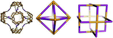 | ||
| Fig. 8 The range of geometric shapes possible for a Tet6Di12 topology cage,35 from an octahedron (middle) to a cuboctahedron (right). The molecule reported on the left is an example of an octahedral shaped cage. | ||
The Tet8Di16 topology is formed from a [8 + 16] reaction and can be related to a square antiprism through an edge-directed assembly of tetratopic BBs on vertices and ditopic BBs on edges. The topology has eight windows of ring size 6 and two larger windows of size 8. There are no crystal structures for this topology, however it was reported by Warmuth and co-workers for the same building blocks as the Tet44Di8 and Tet6Di12 topologies, but using a dichloromethane as the solvent.35 Molecular mechanics simulations suggested that their molecule would maintain a square prism shape that is approximately a spherical ring, as shown in Fig. 9.35
 | ||
| Fig. 9 Example of a Tet8Di16 topology cage reported by Warmuth and co-workers (left) with the geometric shape of a square antiprism (right).35 | ||
The Tet16Di32 topology is formed from a [16 + 32] reaction and can be related to the Archimedean solid of a cuboctahedron through an edge-directed assembly of tetratopic BBs on vertices and ditopic BBs on edges. There are two window sizes, eight of size 6 and six of size 8. There are no synthetic reports of this topology. Finally, there is a Tet24Di48 topology, formed from a [24 + 48] reaction that can be related to another Archimedean solid, the rhombicuboctahedron through edge-directed assembly. There are two window sizes, eight of size 6 and eighteen of size 8. There are also no synthetic reports of this topology, however, Fujita and co-workers have reported the synthesis of a MOP with this topology using square planar Pd2+ as the tetratopic vertex and a dipyridylfuran ligand with an angle of 127° as the edge.34 This structure therefore remains a synthetic design target for an organic cage molecule.
Tritopic + tritopic topology family
Two different tritopic BBs can be combined in a 1![[thin space (1/6-em)]](https://www.rsc.org/images/entities/char_2009.gif) :
:![[thin space (1/6-em)]](https://www.rsc.org/images/entities/char_2009.gif) 1 ratio to form molecular cages. The smallest topology for this family is Tri1Tri1, which consists of a [1 + 1] reaction, with one of each tritopic BB being connected directly to the other tritopic BBs, resulting in three windows of ring size 2. This is shown in Fig. 10, where all the tritopic + tritopic topologies are shown. Provided the tritopic BBs have a concave shape, the resultant organic cage can have an intrinsic internal cavity. This type of topology has been reported by Kataoka et al. via a condensation reaction of a bowl-shaped triboronic acid and a bowl-shaped tri-diol molecule; the resultant capsule was shown to encapsulate small guests.66
1 ratio to form molecular cages. The smallest topology for this family is Tri1Tri1, which consists of a [1 + 1] reaction, with one of each tritopic BB being connected directly to the other tritopic BBs, resulting in three windows of ring size 2. This is shown in Fig. 10, where all the tritopic + tritopic topologies are shown. Provided the tritopic BBs have a concave shape, the resultant organic cage can have an intrinsic internal cavity. This type of topology has been reported by Kataoka et al. via a condensation reaction of a bowl-shaped triboronic acid and a bowl-shaped tri-diol molecule; the resultant capsule was shown to encapsulate small guests.66
 | ||
| Fig. 10 The tritopic + tritopic topology family. One of the tritopic precursors is in blue, the other in teal. | ||
The Tri22Tri2 topology is formed from a [2 + 2] reaction, containing two of each type of tritopic BB, with each BB having one set of double connections and one single connection to the opposite building block. Therefore all BBs have the same connectivity environment and the molecule has two windows of ring size 2 and two of ring size 4. The Tri32Tri3 topology is formed from a [3 + 3] reaction, with two pairs of BBs having double connections and the remainder having single connections. The molecule has two windows of size 2 and four of size 4. There have been no synthetic reports of either the Tri22Tri2 or Tri32Tri3 topology to our knowledge.
The Tri4Tri4 topology is formed from a [4 + 4] reaction and can be related to a tetrahedron through a face-directed assembly, where one of the tritopic BBs is placed on the vertices and another on the faces of the Platonic solid. This type of face-directed assembly has been termed ‘molecular panelling’ when applied to the construction of MOPs.73 All the BBs are singularly linked and there are six windows of ring size 4. This topology has been reported by both Mastalerz and co-workers74 and Cooper and co-workers.67 A molecule with this topology could adopt final shapes ranging from a cube74 to a tetrapod,67 as shown in Fig. 11. For a cubic shape to form, both tritopic BBs could have a similar conformation with (end group)–(centre of mass)–(end group) angles of ∼90°, such that they form the eight corners of the cube between them. For a more tetrapodal shape, one tritopic BB could be planar, with angles of ∼120°, whereas the other could have very narrow angles, acting as the end of each ‘foot’ of the tetrapod.
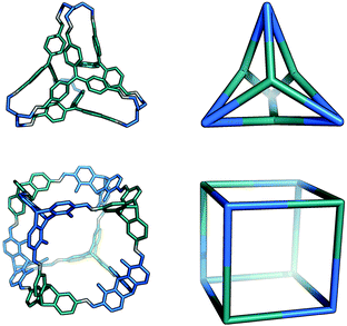 | ||
| Fig. 11 The range of shapes possible for the Tri4Tri4 topology cages, from a tetrapod67 (top), to a cube74 (bottom). | ||
Tetratopic + tritopic topology family
A tetratopic and tritopic BB can be combined in a 3![[thin space (1/6-em)]](https://www.rsc.org/images/entities/char_2009.gif) :
:![[thin space (1/6-em)]](https://www.rsc.org/images/entities/char_2009.gif) 4 ratio to form molecular cages. We identify only one plausible organic cage topology for this system, Tet6Tri8, as shown in Fig. 12. Alternative topologies with fewer components do not form an organic cage, rather open bowl topologies, or require interweaved connections, thus we exclude them here. The Tet6Tri8 topology is formed from a [6 + 8] reaction that can be related to a rhombic dodecahedron by a face-directed assembly, where both tetratopic BBs and tritopic BBs are on the vertices of the polyhedron. This topology consists of twelve windows of ring size 4.
4 ratio to form molecular cages. We identify only one plausible organic cage topology for this system, Tet6Tri8, as shown in Fig. 12. Alternative topologies with fewer components do not form an organic cage, rather open bowl topologies, or require interweaved connections, thus we exclude them here. The Tet6Tri8 topology is formed from a [6 + 8] reaction that can be related to a rhombic dodecahedron by a face-directed assembly, where both tetratopic BBs and tritopic BBs are on the vertices of the polyhedron. This topology consists of twelve windows of ring size 4.
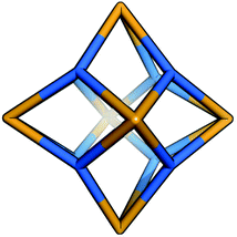 | ||
| Fig. 12 The Tet6Tri8 topology for the tetratopic + tritopic family. Tetratopic precursors are in orange, tritopic in blue. | ||
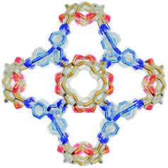
The Tet6Tri8 topology has been reported by Warmuth and co-workers using a tetratopic cavitand and a triphenylamine (although no crystal structure was reported for this experiment)32 and two examples using porphyrin building blocks and triamines by Hong et al. (for which crystal structures are available); the resultant molecules showed selectivity for small gases.68 The range of shapes possible for the Tet6Tri8 topology spans from a rhombic dodecahedron32 through an octahedron to a cube68 as shown in Fig. 13. For a rhombic dodecahedron shape to form, the tritopic and tetratopic BBs should have (end group)–(centre of mass)–(end group) angles of ∼60° and ∼90°, respectively. For a cubic shape to form, the tetratopic BB could be planar, with angles of ∼90° and the tritopic BB acting as a cube corner, with angles of ∼60°.
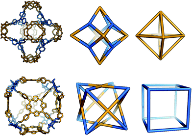 | ||
| Fig. 13 The range of geometric shapes possible for a Tet6Tri8 topology cage. Top: The Tet6Tri8 cage32 can assume the shape of a rhombic dodecahedron (middle) when considering both tetratopic and tritopic precursors as vertices of a solid. It has the shape of an octahedron (right) when only the tetratopic vertices are linked together. Bottom: The Tet6Tri8 cage68 can be seen as a rhombic dodecahedron (middle, as before). It assumes the shape of a cube (right) when only the tritopic precursors are linked together. | ||
In the remainder of this article, we will examine specific case studies for each of the four topology families discussed above. This will allow us to compare the possible reaction outcomes – the alternative topologies that could be formed – and to investigate to what extent computer simulations can assist in predicting the topology from knowledge of the BBs alone.
Methods
In this work, where we consider the topological outcome resulting from the reaction of a pair of BBs, we assemble the possible topologies and then conduct a thorough search of the potential energy landscape for low energy conformations; this is essential, as without care, assumptions can lead to only local energy minimum conformations being found.75 Either a conformer search calculation or a high temperature molecular dynamics simulation (MD) was performed to explore the potential energy surface for each molecule, and to locate the lowest energy conformations using the OPLS3 force field.76 This conformational searching will typically take >1 week for a relatively small cage molecule. More flexible molecules can adopt a large number of different conformations; for example, Fig. 14 shows an overlay of 395 conformations sampled within a 20 kJ mol−1 energy range of the lowest energy conformation during an MD simulation for Tet6Tri8-C (molecule described later in the text). In this specific example, the flexibility of the cage molecule is mainly a result of the possible phenyl ring rotations in the tritopic BB. Of course, more rigid molecules are characterised by a small number of low energy conformers; for example, the Tri4Di6 topology of CC3 has only a single conformation within a 20 kJ mol−1 energy range.In cases where the cage molecule is found to be non-shape persistent, with the lowest energy conformations lacking an internal void, we then proceed with our previously developed enhanced sampling technique to “inflate” the molecules and find the open conformations that lie higher on the potential energy landscape.71 This is essential to compare the conformations that the topologies would be adopting in solution when formed. The time requirements of this procedure naturally increase with molecular size, but as an example, the Tet8Di16 molecule described below required multiple simulations of several weeks duration. Once a collection of open conformations was generated, we performed a further refinement with density functional theory (DFT) calculations in order to obtain more reliable relative energies. Each conformation was geometry optimised with the PBE functional,77 and then its energy value was refined further with a single point calculation with the meta-GGA M06-2X functional.78 Following this, relative internal energies were compared for each family of cages. The use of DCC reactions allowed us to assume that the molecule with the lowest relative energy should be the most synthetically accessible. When the comparison of relative energies was not possible due to molecules containing different BBs, formation energies were calculated instead, with the assumption that the molecule with the lowest formation energy is the most likely to form. For full simulation details, please refer to the ESI.†
Computational challenges
The described procedure allows us to compare the relative internal energies of the hypothetical topologies for a given assembly of BBs, giving an indication of the relative strain (or lack of it), should the BBs adopt those particular topologies. At the start of this paper, we outlined a large number of factors that could influence the topological outcome, some of which we are not able to consider here, based on computational limitations that we will now explain. However, our calculations allow us to uncover to what extent these relative internal energies can explain previous experimental observations.Firstly, in terms of solvent effects, our previously reported “inflation” procedure71 allows us to look at how a solvent influences the conformations of cage molecules. This approach allows us to reproduce the scaffolding or “templating” effect of the solvent molecules, but does not explicitly model individual solvent interactions. To reproduce explicit solvent interactions, we would firstly have to greatly increase the number of atoms in our simulations due to the necessity of including hundreds of solvent molecules; in previous work we found a single cage molecule to be solvated by ∼80 dichloromethane molecules (400 atoms) even in the solid state solvate structure.33 Secondly, we would then need to sample the conformations of these molecules surrounding the cage molecule to consider the dynamic nature of the solvation. Combined, these simulations are not currently tractable for these systems. An alternative implicit solvation approach, where a dielectric constant is applied to reproduce the dielectric screening a molecule in solution experiences, does not reproduce the scaffolding effect of the solvent, and our preliminary tests have found this to make no significant difference to the relative energies of cage topologies. This issue of solvent effect remains a big challenge in the field and efficient approaches need to be developed for the modelling of such complex systems.
Ideally we would go beyond the relative internal energies from DFT calculations and compare free energies. This would include a consideration of the translational, rotational and vibrational entropy of the systems, which should tend to disfavour the formation of larger assemblies over smaller ones. Practically, this would require a frequency analysis for each molecular conformation, and this is computationally intractable on a routine basis even for the smaller cage systems. Indeed, in our previous work we had to resort to considering only fragments of a comparably small molecular cage for calculations of the free energy correction to guest binding energies to be tractable.79
Whilst not the focus of our work, one can also consider the use of simulations to predict preferential catenane formation over monomeric forms of the topologies discussed. Catenanes could be expected to form as thermodynamic products if a combination of solvent interactions, steric compatibility of the BBs involved in the reaction, and the formation of stabilising interactions between the two monomeric units act as a thermodynamic driving force. The obvious starting point for simulations is to calculate the binding energy of a catenane pair by comparing the total energy to that of two gas phase monomers. An unfavourable binding energy, for example resulting from steric clashes of the molecules in a catenated form, would suggest that the monomeric form would be preferred. However, favourable binding energies would need to be considered with caution, as these would indicate stabilisation of the catenane relative only to isolated gas phase monomers, without consideration of stabilisation of those monomers by either solvent interactions or intermolecular interactions gained via crystal packing. Thus, arguably, for a series of systems, binding energies might be best used to qualitatively rank a series of monomers in terms of the likelihood of catenane preference over monomeric forms. We further note that for some systems there would be significant, and even potentially prohibitive, sampling requirements when looking for low energy catenated forms. These would arise from the requirement to consider both different mechanical interlocking arrangements and also configurational sampling for each interlocked form. Finally, reliable binding energies across a series of different systems are likely to require DFT calculations, rather than computationally cheaper forcefield calculations.
Results
The tritopic + ditopic family: CC3
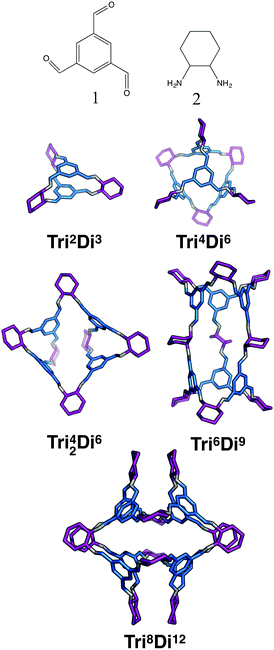
For the tritopic + ditopic family, we investigated the outcome of combining 1,3,5-triformylbenzene (1 in Fig. 15) and (R,R)-1,2-diaminocyclohexane (2 in Fig. 15), used in the synthesis of CC3, a Tri4Di6 imine molecule.27,80 The relative energies per [2 + 3] unit were compared for the lowest energy conformations of the Tri2Di3, Tri4Di6, Tri42Di6, Tri6Di9 and Tri8Di12 topologies. The structures of the lowest energy open conformations are shown in Fig. 15, with the relative energies in Fig. 16 and Table 3. The Tri2Di3, Tri4Di6, and Tri42Di6 topologies exhibit shape persistency, whereas the larger Tri6Di9 and Tri8Di12 topologies are more flexible and collapse under MD simulations, losing their internal cavities. Constrained MD simulations on the latter two topologies were able to find higher energy open metastable states, 4 and 2 kJ mol−1 per [2 + 3] unit above the collapsed conformations for Tri6Di9 and Tri8Di12 respectively. We compare the relative energies of the open conformations only, as these are likely the structures that initially form in the reaction solution, and therefore comparison between these structures is most pertinent for determining the likely reaction outcome.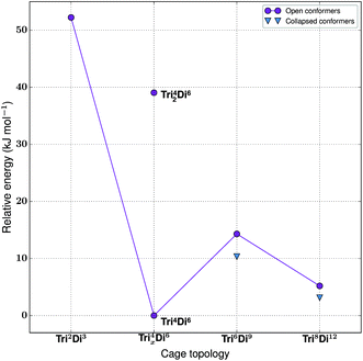 | ||
| Fig. 16 The relative energies of the lowest energy conformations of the CC3-based tritopic + ditopic topologies, as calculated by M06-2X. | ||
| Synthetically realised? | Energy relative to Tri4Di6 per [2 + 3] unit (kJ mol−1) | Shape persistent? | Void diameter (Å) | |
|---|---|---|---|---|
| Tri 2 Di 3 | No | 52 | Yes | 1.3 |
| Tri 4 Di 6 | Yes | 0 | Yes | 5.5 |
| Tri 42 Di 6 | No | 39 | Yes | 3.1 |
| Tri 6 Di 9 | No | 14 | No | 5.2 |
| Tri 8 Di 12 | No | 5 | No | 7.4 |
The Tri4Di6 molecule lies lowest in energy and is the synthetically realised topology, which can therefore be rationalised on the energy of the gas phase conformations alone. This is followed by the higher energy metastable inflated conformers of Tri8Di12 (5 kJ mol−1 per [2 + 3] unit) and Tri6Di9 (14 kJ mol−1 per [2 + 3] unit). An alternative topology is available with a [4 + 6] reaction, in which precursors are assembled into a doubly-bonded ring to give Tri42Di6, however this is considerably higher in energy (39 kJ mol−1 per [2 + 3] unit). The Tri2Di3, in which the precursors are assembled into a capsule, is the topology with the highest energy, 52 kJ mol−1 per [2 + 3] unit higher, unsurprisingly the geometry is characterised by a high degree of strain. To compare not only the topological prediction, but also the structure prediction, we overlaid our predicted structure of the Tri4Di6CC3 molecule to that of the single crystal X-ray diffraction structure.27 We found a Root Mean Square Deviation (RMSD) value of 0.107 Å, showing that the conformation is well reproduced, as shown in Fig. S1-A.†
The tritopic + ditopic family: CC5 and CC8
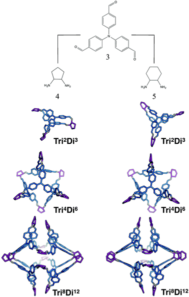
For the tritopic + ditopic family, we investigated a further case that has been reported as an example of emergent behaviour. When tris(4-formylphenyl)amine (3 in Fig. 17) and (1S,2S)-cyclopentanediamine (4 in Fig. 17) are combined, they produce the porous Tri4Di6CC5 molecule, but changing the diamine to (R,R)-1,2-diaminocyclohexene (5 in Fig. 17), adding only an additional CH2 group, results in a Tri8Di12CC8 molecule, which is non-porous and lacks shape persistence.33,81 The relative energies per [2 + 3] unit and structures for the lowest energy conformations of the Tri2Di3, Tri4Di6, and Tri8Di12 topologies were compared. The structures are shown in Fig. 17 and the energies in Fig. 18 and Table 4. The Tri2Di3 topology is too small to contain a cavity, whereas the Tri4Di6 molecules are shape persistent with cavities ∼7 Å in diameter. However, both Tri8Di12 structures collapse, as is known experimentally for the CC8 molecule, losing their internal cavities. Constrained MD simulations on the Tri8Di12 structures were used to find higher energy open metastable states, 21 and 28 kJ mol−1 per [2 + 3] unit above the collapsed conformations for CC5 and CC8 respectively.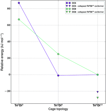 | ||
| Fig. 18 The relative energies of the lowest energy conformations of the CC5 and CC8-based ditopic + tritopic topologies, as calculated by M06-2X. | ||
| Synthetically realised? | Energy relative to Tri8Di12 per [2 + 3] unit (kJ mol−1) | Shape persistent? | Void diameter (Å) | |
|---|---|---|---|---|
| CC5 Tri 2 Di 3 | No | 87 | — | 0.4 |
| CC5 Tri 4 Di 6 | Yes | −1 | Yes | 7.3 |
| CC5 Tri 8 Di 12 | No | 0 | No | 10.1 |
| CC8 Tri 2 Di 3 | No | 67 | — | 1.6 |
| CC8 Tri 4 Di 6 | No | 25 | Yes | 6.5 |
| CC8 Tri 8 Di 12 | Yes | 0 | No | 9.2 |
For both cage families, the Tri2Di3 molecule, with only two carbon atoms bridging the tritopic BBs, is strained and consequently high in energy compared to the other topological possibilities in all cases (by >40 kJ mol−1). It is not surprising therefore that this topology is not experimentally observed. For the CC8 molecule, the lowest energy conformation has the large Tri8Di12 topology, with an approximately octahedral symmetry. This corresponds to the experimental reports of this molecule formed with the diaminocyclohexene group.33 As we previously reported,71 the computed open conformation for CC8 is a good match to the single crystal X-ray diffraction structure of the solvate (with an RMSD value of 1.672 Å, see Fig. S2-A†), which improves slightly when minimising the single crystal structure (with the RMSD value moving to 0.629 Å, see Fig. S2-B†), suggesting some influence of the solvent molecules in opening the vertices slightly outwards.
For the CC5 molecule, there was a very different result to the CC8 molecule; now there is no clear preference between the Tri4Di6 and Tri8Di12 molecules, with a relative energy difference of only 1 kJ mol−1 per [2 + 3] unit. This molecule has in fact been synthetically realised only as a Tri4Di6 topology, which had a BET SA of 1333 m2 g−1.81 An overlay of the computed and single crystal X-ray diffraction structure of the solvate (see Fig. S3†) finds a good match, with an RMSD of 0.706 Å. Again, this match improves when the solvate conformation is geometry optimised (RMSD of 0.449 Å), which contracts the molecule, suggesting a scaffolding effect of the solvent that is lost in the calculations when the conformation is completely energy minimised after our artificial inflation procedure. In this case therefore, the calculations would not have been able to successfully distinguish between whether a Tri4Di6 or Tri8Di12 topology was formed, although it was clearly a different scenario to the CC8 topological energy landscape. We attribute this to our not being able to consider all solvent effects in our simulations (as evidenced by the overlays). Further, as discussed in the Computational challenges section, if the entropic contribution to the free energies was able to be considered, this can be expected to destabilise the larger Tri8Di12 topology relative to the Tri4Di6.
The tritopic + tritopic family
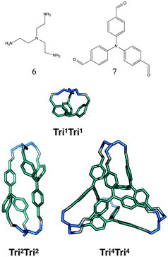
For the tritopic + tritopic family, we investigated the reaction of tris(2-aminoethyl)amine (6 in Fig. 19) and tris(4-formylphenyl)aldehyde (7 in Fig. 19), used in the synthesis of CC11, a tetrapodal-shape Tri4Tri4 molecule.67 The relative energies per [1 + 1] unit were compared for the lowest energy conformations of the Tri1Tri1, Tri2Tri2 and Tri4Tri4 topologies. The structures of the lowest energy conformations are shown in Fig. 19, with the relative energies shown in Fig. 20 and Table 5. Both Tri1Tri1 and Tri2Tri2 present very strained geometries and therefore their energy is hundreds of kJ mol−1 higher than that of Tri4Tri4 (376 and 123 kJ mol−1 per [1 + 1] unit, respectively). This is in agreement with the experimental result, where it is the Tri4Tri4 topology with a tetrapodal shape that is formed. When we compared it with the single crystal X-ray diffraction structure, we find an RMSD of 0.548 Å, with a good match of our predicted structure to the experimentally reported one (see Fig. S1-B†).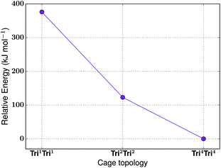 | ||
| Fig. 20 The relative energies of the lowest energy conformations of the CC11-based tritopic + tritopic topologies, as calculated by M06-2X. | ||
| Synthetically realised? | Energy relative to Tri4Tri4 per [1 + 1] unit (kJ mol−1) | Shape persistent? | Void diameter (Å) | |
|---|---|---|---|---|
| Tri 1 Tri 1 | No | 376 | — | 1.2 |
| Tri 2 Tri 2 | No | 123 | — | 0.4 |
| Tri 4 Tri 4 | Yes | 0 | Yes | 3.2 |
The tetratopic + ditopic family
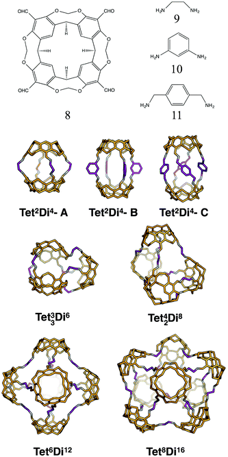
For the tetratopic + ditopic family, we investigated the reaction of the tetraformylcavitand (8 in Fig. 21) and ethylene-1,2-diamine (9 in Fig. 21), reported by Warmuth and co-workers to produce a mixture of Tet42Di8, Tet6Di12 and Tet8Di16 topology molecules, dependent upon the solvent used.35 Five different molecules were generated, Tet2Di4, Tet3Di6, Tet42Di8, Tet6Di12 and Tet8Di16. In the MD simulations, Tet2Di4, Tet33Di6 and Tet42Di8 were found to be shape persistent, whereas the larger Tet6Di12 and Tet8Di16 topologies were not. Constrained MD simulations on the latter two were able to locate metastable, higher energy open conformations. The structures of the lowest energy open conformations are shown in Fig. 21, with the relative energies shown in Fig. 22 and reported in Table 6.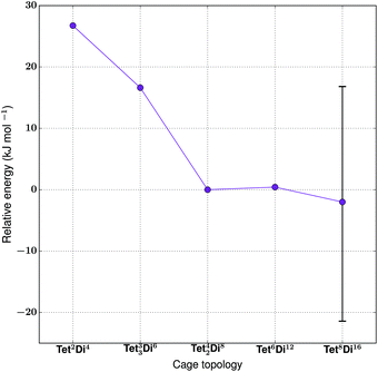 | ||
| Fig. 22 The relative energies of the lowest energy conformations of the Warmuth tetratopic + tritopic topologies, as calculated by M06-2X. The error bar on point Tet8Di16 shows the range of energies covered by conformations with differing degrees of inflation (see Table S1 and Fig. S4†), with more open conformers displaying higher energies. | ||
| Synthetically realised? | Energy relative to Tet4Di8 per [1 + 2] unit (kJ mol−1) | Relative formation energy per bond formed (kJ mol−1) | Shape persistent? | Void diameter (Å) | |
|---|---|---|---|---|---|
| Tet 2 Di 4 -A | No | 27 | 8 | Yes | 5.8 |
| Tet 2 Di 4 -B | Yes | — | 6 | Yes | 5.1 |
| Tet 2 Di 4 -C | Yes | — | 0 | Yes | 4.6 |
| Tet 3 Di 6 | No | 17 | — | Yes | 3.1 |
| Tet 42 Di 8 | Yes | 0 | — | Yes | 6.3 |
| Tet 6 Di 12 | Yes | 1 | — | No | 12.3 |
| Tet 8 Di 16 | Yes | Range from −21 to 17 | — | No | 8.4–10.4 |
The cage with the lowest energy was a partially collapsed conformer of Tet8Di16. The cage was not found to be shape persistent after high temperature MD, and the inflating procedure provided us with a very large number of higher energy metastable conformers, some of which were partially open, like the lowest energy one reported, and others containing a larger pore size (as shown in Fig. S4†). As no crystal structure was available and it was not possible to be certain whether a single conformation represented the open structure, we plot the range of energies found for conformations with varying pore sizes in Fig. 22 and show the conformation with the widest pore diameter (10.4 Å) in Fig. 21. This more open conformation is located 38 kJ mol−1 above the less inflated lower energy conformer, which has a smaller pore diameter of 8.4 Å. The degree of strain of the structure increases with the degree of inflation.
Experimentally, the formation of Tet8Di16 was obtained using CH2Cl2 as a solvent. We carried out a structural analysis on the resulting cage, in order to understand whether it was possible to relate the solvent used during the synthesis to the final topology. Tet8Di16 has 10 windows, with diameters that range from 4–6 Å for the 8 triangular windows and from 6–9 Å for the 2 square windows, depending on the degree of inflation (see Table S1†). About 22 and 21 kJ mol−1 above the lowest energy conformer of Tet8Di16 are Tet6Di12 and Tet42Di8, that were respectively found experimentally in THF and chloroform. We analysed their windows’ diameters (an average of 5.2 Å for the 8 triangular windows of the octahedral Tet6Di12, and an average of 5.6 Å for the 4 biggest windows of Tet42Di8), but we were not able to find any geometric correlation between the solvent used for the synthesis and the cage topologies. We leave this particular aspect to further studies.
The hypothetical topologies we generated, Tet33Di6 and Tet2Di4, are more strained and thus higher in energy, explaining the fact that they have not been experimentally observed. They are located respectively 17 and 27 kJ mol−1 higher than Tet42Di8. We then investigated the effect of changing the ditopic BB's geometry on the topological landscape. The study carried out by Warmuth and co-workers suggested that it was not possible to synthesise a cage with the shape of a Tet2Di4 capsule when using ethylene-1,2-diamine, which is rationalisable by the fact that it lies 27 kJ mol−1 higher in energy per [1 + 2] unit than the observed Tet42Di8 topology.35 However, they did find that the Tet2Di4 capsule could be formed by using different ditopic BBs, benzenes amino-functionalised in the meta or para position. We therefore generated two capsules in a [2 + 4] ratio, Tet2Di4-B and Tet2Di4-C, using m-phenylenediamine (10) and the chiral precursor p-xylylenediamine (11) respectively. As these molecules contain different BBs, we cannot directly compare their relative energies per formula unit, and therefore instead compare the relative formation energies of the three capsular Tet2Di4 molecules (see Table 6). In agreement with experimental results, both cages B and C are lower in energy than A, in particular Tet2Di4-C is 6 kJ mol−1 per imine bond lower than Tet2Di4-B, and Tet2Di4-C is 8 kJ mol−1 lower than Tet2Di4-A. This is because kinked or twisted diamines allow the two cavitands to align in a more stable and less hindered conformation than when using BB 9. The latter should adopt a very strained gauche conformation to permit the cavitands to align in the coplanar conformation required to reduce the strain.
The tetratopic + tritopic family
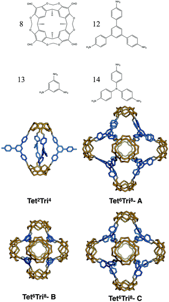
Finally, for the (tetratopic + tritopic) family, we investigated the reaction of the tetraformylcavitand (8 in Fig. 23) and 1,3,5-tris(4-aminophenyl)benzene (12 in Fig. 23) to form a Tet6Tri8 molecule, as previously reported by Warmuth and co-workers.32 We constructed models with the BBs mixed in both a [6 + 8] ratio and in a [2 + 4] ratio; both topologies were observed depending upon whether a 3 aldehyde![[thin space (1/6-em)]](https://www.rsc.org/images/entities/char_2009.gif) :
:![[thin space (1/6-em)]](https://www.rsc.org/images/entities/char_2009.gif) 4 amine stoichiometric ratio was used experimentally (resulting in Tet6Tri8) or an excess of the amine was used (resulting in a capsule Tet2Tri4 with 3 unreacted amine groups). The lowest energy conformations are shown in Fig. 23. The relative formation energies of the two topologies were compared (reported in Table 7) and found to be very similar (within 1 kJ mol−1). Such a small difference in energy would explain why both topologies were experimentally observed in solution. Although the presence of the molecules in solutions was identified by Warmuth and coworkers with different techniques such as 1H NMR, 13C NMR and MALDI-TOF, the structures were never isolated from the solvent and neither solvated or desolvated crystal structures are currently available, therefore a direct geometric comparison between experimental and computed structures is not currently possible. Nevertheless, the calculations seem to suggest that the lowest energy conformers of both the capsule and rhombic dodecahedron cage are shape persistent and porous, therefore of synthetic interest. The void dimensions of both molecules were calculated and reported in Table 7. Tet2Tri4 shows a void diameter of 9.9 Å, and Tet6Tri8 of 17.8 Å, which is very close to the 20.6 Å void diameter of the boronate cube synthesised by Mastalerz and coworkers, which currently holds the record for the molecule with the biggest intrinsic pore synthesised.
4 amine stoichiometric ratio was used experimentally (resulting in Tet6Tri8) or an excess of the amine was used (resulting in a capsule Tet2Tri4 with 3 unreacted amine groups). The lowest energy conformations are shown in Fig. 23. The relative formation energies of the two topologies were compared (reported in Table 7) and found to be very similar (within 1 kJ mol−1). Such a small difference in energy would explain why both topologies were experimentally observed in solution. Although the presence of the molecules in solutions was identified by Warmuth and coworkers with different techniques such as 1H NMR, 13C NMR and MALDI-TOF, the structures were never isolated from the solvent and neither solvated or desolvated crystal structures are currently available, therefore a direct geometric comparison between experimental and computed structures is not currently possible. Nevertheless, the calculations seem to suggest that the lowest energy conformers of both the capsule and rhombic dodecahedron cage are shape persistent and porous, therefore of synthetic interest. The void dimensions of both molecules were calculated and reported in Table 7. Tet2Tri4 shows a void diameter of 9.9 Å, and Tet6Tri8 of 17.8 Å, which is very close to the 20.6 Å void diameter of the boronate cube synthesised by Mastalerz and coworkers, which currently holds the record for the molecule with the biggest intrinsic pore synthesised.
| Synthetically realised? | Relative formation energy per bond formed (kJ mol−1) | Shape persistent? | Void diameter (Å) | |
|---|---|---|---|---|
| Tet 2 Tri 4 | Yes | 3 | Yes | 9.9 |
| Tet 6 Tri 8 -A | Yes | 4 | Yes | 17.8 |
| Tet 6 Tri 8 -B | No | 3 | Yes | 12.2 |
| Tet 6 Tri 8 -C | No | 0 | Yes | 15.5 |
Considering the possible interest in a porous molecule of this cavity volume, the effect of the size of the triamine BB was investigated and two similar molecules with the Tet6Tri8 topology were generated. Cavitand 8 was mixed with 1,3,5-triaminobenzene (13) to give Tet6Tri8-B and with 4,4′,4-triaminotriphenylamine (14) to obtain Tet6Tri8-C. Both molecules were found to be shape persistent and therefore the formation energies per bond were calculated and compared to that of Tet6Tri8-A (see Table 7). Tet6Tri8-B was found to have a formation energy ∼1 kJ mol−1 lower than Tet6Tri8-A, thus is potentially equally likely to form. Tet6Tri8-C shows a less strained geometry; we attribute this to the central nitrogen atom on each tritopic BB allowing rotational freedom, bringing the formation energy 4 kJ mol−1 per imine bond lower than Tet6Tri8-A. This suggests that Tet6Tri8-C could be a particularly promising synthetic target. Both molecules are porous, showing respectively a shape persistent pore diameter of 12.2 Å and 15.5 Å.
Conclusions
We have enumerated the 20 possible topologies that can be used as underlying structures for the design and the synthesis of new porous organic molecules. We have suggested a naming convention that relies on the type, number and multiplicity of connectivity of the BB and propose that this will cause less confusion than naming based on relationships to Platonic or Archimedean solids. Whilst 12 of these topologies have already been synthetically realised, several interesting target candidates have also been identified.We have tested to what extent calculations focusing on relative internal energies can assist in the prediction of topological outcomes for a given DCC reaction that should afford the thermodynamic product. This approach was successful in the majority of the BB combinations we examined, including for CC3, CC5, CC11, the (tetratopic + ditopic) family from Warmuth and the (tetratopic + tritopic) family from Warmuth. However, for the case of the emergent behaviour in the CC5 and CC8 systems, whilst we can correctly identify that the cyclohexane BB leads to a Tri8Di12 topology, for the cyclopentane BB, we could not distinguish between the relative energies of Tri4Di6 and Tri8Di12, thus not correctly identifying the experimental outcome of a Tri4Di6 topology. We believe that this result is likely due to a combination of the influence of the solvent in disturbing the energy landscape and an entropic contribution disfavouring the larger topology, which we were not able to directly include in our simulations. For the Warmuth (tetratopic + ditopic) family, where the topology is known to be influenced by solvent choice, we were not able to find any obvious geometric correlation between the structures and the successful solvent, thus this remains the subject of future research.
We highlight the design opportunity behind using simulations to consider the thermodynamic viability of a given target, which, together with chemical intuition, can provide new developments for this emerging field. The natural evolution of this project would be to explore the topological outcome for a much wider library of precursors with different topicity, length, angles, and rigidity, with the goal being to rationalise which criteria would favour the formation of promising porous organic cages. However, we have shown here computational challenges with modelling a relatively small set of organic precursors, suggesting that the brute force screening of large libraries is not currently computationally feasible. Instead, we would suggest it is better to focus on answering specific questions with smaller library subsets, such as: how does variation in the BB geometry influence topological outcome? Which BBs provide the most promising route to a desired topology? Which BB features are most critical to shape persistence in a desired topology?
Acknowledgements
We acknowledge a Royal Society University Research Fellowship (KEJ), the ERC (ADG-2012-321156-ROBOT), and the EPSRC (EP/M017257/1 and EP/N004884/1) for funding and ARCHER time through the Materials Chemistry Consortium (EP/L000202).References
- O. M. Yaghi, M. O'Keeffe and M. Kanatzidis, J. Solid State Chem., 2000, 152, 1–2 CrossRef CAS.
- M. O'Keeffe and O. M. Yaghi, Chem. Rev., 2012, 112, 675–702 CrossRef PubMed.
- O. Delgado-Friedrichs, M. D. Foster, M. O'Keeffe, D. M. Proserpio, M. M. J. Treacy and O. M. Yaghi, J. Solid State Chem., 2005, 178, 2533–2554 CrossRef CAS.
- M. O'Keeffe, M. A. Peskov, S. J. Ramsden and O. M. Yaghi, Acc. Chem. Res., 2008, 41, 1782–1789 CrossRef PubMed.
- E. V. Alexandrov, V. A. Blatov, A. V. Kochetkov and D. M. Proserpio, CrystEngComm, 2011, 13, 3947–3958 RSC.
- O. M. Yaghi, M. O'Keeffe, N. W. Ockwig, H. K. Chae, M. Eddaoudi and J. Kim, Nat. Commun., 2003, 423, 705–714 CrossRef CAS PubMed.
- R. S. Forgan, J.-P. Sauvage and J. F. Stoddart, Chem. Rev, 2011, 111, 5434–5464 CrossRef CAS PubMed.
- R. Chakrabarty, P. S. Mukherjee and P. J. Stang, Chem. Rev., 2011, 111, 6810–6918 CrossRef CAS PubMed.
- G. Zhang and M. Mastalerz, Chem. Soc. Rev., 2014, 43, 1934–1947 RSC.
- M. Mastalerz, Angew. Chem., Int. Ed., 2010, 49, 5042–5053 CrossRef CAS PubMed.
- J. R. Holst, A. Trewin and A. I. Cooper, Nat. Chem., 2010, 2, 915–920 CrossRef CAS PubMed.
- J. Tian, P. K. Thallapally and B. P. McGrail, CrystEngComm, 2012, 14, 1909–1919 RSC.
- T. Hasell and A. I. Cooper, Nat. Rev. Mater., 2016, 1, 1–15 CrossRef.
- B. Dietrich, J. M. Lehn and J. P. Sauvage, Tetrahedron Lett., 1969, 10, 2889–2892 CrossRef.
- D. J. Cram, S. Karbach, Y. H. Kim, L. Baczynskyj and G. W. Kallemeyn, J. Am. Chem. Soc., 1985, 107, 2575–2576 CrossRef CAS.
- P. Stutte, W. Kiggen and F. Vögtle, Tetrahedron, 1987, 43, 2065–2074 CrossRef CAS.
- M. Yoshizawa, J. K. Klosterman and M. Fujita, Angew. Chem., Int. Ed., 2009, 48, 3418–3438 CrossRef CAS PubMed.
- T.-C. Lee, E. Kalenius, A. I. Lazar, K. I. Assaf, N. Kuhnert, C. H. Grün, J. Jänis, O. A. Scherman and W. M. Nau, Nat. Chem., 2013, 5, 376–382 CrossRef CAS PubMed.
- A. Kewley, A. Stephenson, L. Chen, M. E. Briggs, T. Hasell and A. I. Cooper, Chem. Mater., 2015, 27, 3207–3210 CrossRef CAS.
- T. Mitra, K. E. Jelfs, M. Schmidtmann, A. Ahmed, S. Y. Chong, D. J. Adams and A. I. Cooper, Nat. Chem., 2013, 5, 276–281 CrossRef CAS PubMed.
- T. Hasell, M. Miklitz, A. Stephenson, M. A. Little, S. Y. Chong, R. Clowes, L. Chen, D. Holden, G. A. Tribello, K. E. Jelfs and A. I. Cooper, J. Am. Chem. Soc., 2016, 138, 1653–1659 CrossRef CAS PubMed.
- L. Chen, P. S. Reiss, S. Y. Chong, D. Holden, K. E. Jelfs, T. Hasell, M. A. Little, A. Kewley, M. E. Briggs, A. Stephenson, K. M. Thomas, J. A. Armstrong, J. Bell, J. Busto, R. Noel, J. Liu, D. M. Strachan, P. K. Thallapally and A. I. Cooper, Nat. Mater., 2014, 13, 954–960 CrossRef CAS PubMed.
- M. Brutschy, M. W. Schneider, M. Mastalerz and S. R. Waldvogel, Adv. Mater, 2012, 24, 6049–6052 CrossRef CAS PubMed.
- K. Acharyya and P. S. Mukherjee, Chem. Commun, 2014, 50, 15788–15791 RSC.
- N. Giri, M. G. Del Pópolo, G. Melaugh, R. L. Greenaway, K. Rätzke, T. Koschine, L. Pison, M. F. C. Gomes, A. I. Cooper and S. L. James, Nat. Commun., 2015, 527, 216–220 CrossRef CAS PubMed.
- S. Lee, A. Yang, T. P. Moneypenny II and J. S. Moore, J. Am. Chem. Soc., 2016, 138, 2182–2185 CrossRef CAS PubMed.
- T. Tozawa, J. T. A. Jones, S. I. Swamy, S. Jiang, D. J. Adams, S. Shakespeare, R. Clowes, D. Bradshaw, T. Hasell, S. Y. Chong, C. Tang, S. Thompson, J. Parker, A. Trewin, J. Bacsa, A. M. Z. Slawin, A. Steiner and A. I. Cooper, Nat. Mater., 2009, 8, 973–978 CrossRef CAS PubMed.
- G. O. Brunner, Z. Kristallogr., 1981, 156, 295–303 CAS.
- N. J. Young and B. P. Hay, Chem. Commun., 2013, 49, 1354–1379 RSC.
- D. Xu and R. Warmuth, J. Am. Chem. Soc., 2008, 130, 7520–7521 CrossRef CAS PubMed.
- S. Klotzbach, T. Scherpf and F. Beuerle, Chem. Commun., 2014, 50, 12454–12457 RSC.
- Y. Liu, X. Liu and R. Warmuth, Chem. – Eur. J., 2007, 13, 8953–8959 CrossRef CAS PubMed.
- K. E. Jelfs, X. Wu, M. Schmidtmann, J. T. A. Jones, J. E. Warren, D. J. Adams and A. I. Cooper, Angew. Chem., Int. Ed., 2011, 50, 10653–10656 CrossRef CAS PubMed.
- Q. F. Sun, J. Iwasa, D. Ogawa, Y. Ishido, S. Sato, T. Ozeki, Y. Sei, K. Yamaguchi and M. Fujita, Science, 2010, 328, 1144–1147 CrossRef CAS PubMed.
- X. Liu and R. Warmuth, J. Am. Chem. Soc., 2006, 128, 14120–14127 CrossRef CAS PubMed.
- E. L. Elliott, C. S. Hartley and J. S. Moore, Chem. Commun., 2011, 47, 5028–5024 RSC.
- T. Hasell, X. Wu, J. T. A. Jones, J. Bacsa, A. Steiner, T. Mitra, A. Trewin, D. J. Adams and A. I. Cooper, Nat. Chem., 2010, 2, 750–755 CrossRef CAS PubMed.
- G. Zhang, O. Presly, F. White, I. M. Oppel and M. Mastalerz, Angew. Chem., Int. Ed., 2014, 53, 5126–5130 CAS.
- D. P. Lydon, N. L. Campbell, D. J. Adams and A. I. Cooper, Synth. Commun., 2011, 41, 2146–2151 CrossRef CAS.
- D. J. Tranchemontagne, Z. Ni, M. O'Keeffe and O. M. Yaghi, Angew. Chem., Int. Ed., 2008, 47, 5136–5147 CrossRef CAS PubMed.
- S. K. Lin, J. Chem. Inf. Model., 1996, 36, 367–376 CrossRef CAS.
- M. K. Gilson and K. K. Irikura, J. Phys. Chem. B, 2010, 114, 16304–16317 CrossRef CAS PubMed.
- G. Ercolani, C. Piguet, M. Borkovec and J. Hamacek, J. Phys. Chem. B, 2007, 111, 12195–12203 CrossRef CAS PubMed.
- P. Skowronek, B. Warzajtis, U. Rychlewska and J. Gawronski, Chem. Commun., 2013, 49, 2524–2526 RSC.
- D. B. Amabilino, Template Strategies in Self-Assembly, John Wiley & Sons, Ltd, Chichester, UK, 2012 Search PubMed.
- M. Rekharsky and Y. Inoue, Solvation Effects in Supramolecular Recognition, John Wiley & Sons, Ltd, Chichester, UK, 2012 Search PubMed.
- Y. Jin, A. Jin, R. McCaffrey, H. Long and W. Zhang, J. Org. Chem., 2012, 77, 7392–7400 CrossRef CAS PubMed.
- M. E. Briggs, A. G. Slater, N. Lunt, S. Jiang, M. A. Little, R. L. Greenaway, T. Hasell, C. Battilocchio, S. V. Ley and A. I. Cooper, Chem. Commun., 2015, 51, 17390–17393 RSC.
- M. Kitchin, K. Konstas, C. J. Sumby, M. L. Czyz, P. Valente, M. R. Hill, A. Polyzos and C. J. Doonan, Chem. Commun, 2015, 51, 14231–14234 RSC.
- B. Içli, N. Christinat, J. Tönnemann, C. Schüttler, R. Scopelliti and K. Severin, J. Am. Chem. Soc., 2009, 131, 3154–3155 CrossRef PubMed.
- D. Barth, O. David, F. Quessette, V. Reinhard, Y. Strozecki and S. Vial, Lect. Notes Comput. Sci., 2015, 9125, 235–246 Search PubMed.
- K. D. Okochi, G. S. Han, I. M. Aldridge, Y. Liu and W. Zhang, Org. Lett., 2013, 15, 4296–4299 CrossRef CAS PubMed.
- A. Dhara and F. Beuerle, Chem. – Eur. J., 2015, 21, 17391–17396 CrossRef CAS PubMed.
- S. Klotzbach and F. Beuerle, Angew. Chem., Int. Ed., 2015, 127, 10497–10502 CrossRef.
- S. Jiang, J. T. A. Jones, T. Hasell, D. Bléger, C. E. Blythe, D. J. Adams, A. Trewin and A. I. Cooper, Nat. Commun., 2011, 2, 1–7 CAS.
- N. Christinat, R. Scopelliti and K. Severin, Angew. Chem., Int. Ed., 2008, 47, 1848–1852 CrossRef CAS PubMed.
- P. Kieryk, J. Janczak, J. Panek, M. Miklitz and J. Lisowski, Org. Lett., 2016, 18, 12–15 CrossRef CAS PubMed.
- H. Takahagi, S. Fujibe and N. Iwasawa, Chem. – Eur. J., 2009, 15, 13327–13330 CrossRef CAS PubMed.
- M. W. Schneider, I. M. Oppel and M. Mastalerz, Chem. – Eur. J., 2012, 18, 4156–4160 CrossRef CAS PubMed.
- H. Ding, Y. Yang, B. Li, F. Pan, G. Zhu, M. Zeller, D. Yuan and C. Wang, Chem. Commun., 2015, 51, 1976–1979 RSC.
- M. Mastalerz, Chem. Commun., 2008, 4756–4758 RSC.
- G. Zhang, O. Presly, F. White, I. M. Oppel and M. Mastalerz, Angew. Chem., Int. Ed., 2014, 53, 1516–1520 CrossRef CAS PubMed.
- R. Warmuth, E. F. Maverick, C. B. Knobler and D. J. Cram, J. Org. Chem., 2003, 68, 2077–2088 CrossRef CAS PubMed.
- V. Barba and I. Betanzos, J. Organomet. Chem., 2007, 692, 4903–4908 CrossRef CAS.
- J. Sun, J. Bennett, R. Emge and R. Warmuth, J. Am. Chem. Soc., 2011, 133, 3268–3271 CrossRef CAS PubMed.
- K. Kataoka, T. D. James and Y. Kubo, J. Am. Chem. Soc., 2007, 129, 15126–15127 CrossRef CAS PubMed.
- M. E. Briggs, K. E. Jelfs, S. Y. Chong, C. Lester, M. Schmidtmann, D. J. Adams and A. I. Cooper, Cryst. Growth Des., 2013, 13, 4993–5000 CAS.
- S. Hong, M. R. Rohman, J. Jia, Y. Kim, D. Moon, Y. Kim, Y. H. Ko, E. Lee and K. Kim, Angew. Chem., Int. Ed., 2015, 13241–13244 CrossRef CAS PubMed.
- Q. Wang, C. Zhang, B. C. Noll, H. Long, Y. Jin and W. Zhang, Angew. Chem., Int. Ed., 2014, 53, 10663–10667 CrossRef CAS PubMed.
- Y. Jin, B. A. Voss, R. D. Noble and W. Zhang, Angew. Chem., Int. Ed., 2010, 49, 6348–6351 CrossRef CAS PubMed.
- V. Santolini, G. A. Tribello and K. E. Jelfs, Chem. Commun., 2015, 51, 15542–15545 RSC.
- B. Olenyuk, M. D. Levin, J. A. Whiteford, J. E. Shield and P. J. Stang, J. Am. Chem. Soc., 1999, 121, 10434–10435 CrossRef CAS.
- M. Fujita, K. Umemoto, M. Yoshizawa, N. Fujita, T. Kusukawa and K. Biradha, Chem. Commun., 2001, 509–518 RSC.
- S. M. Elbert, F. Rominger and M. Mastalerz, Chem. – Eur. J., 2014, 20, 16707–16720 CrossRef CAS PubMed.
- K. E. Jelfs and A. I. Cooper, Curr. Opin. Solid State Mater. Sci., 2013, 17, 19–30 CrossRef CAS.
- E. Harder, W. Damm, J. Maple, C. Wu, M. Reboul, J. Y. Xiang, L. Wang, D. Lupyan, M. K. Dahlgren, J. L. Knight, J. W. Kaus, D. S. Cerutti, G. Krilov, W. L. Jorgensen, R. Abel and R. A. Friesner, J. Chem. Theory Comput., 2016, 12, 281–296 CrossRef CAS PubMed.
- J. Perdew, K. Burke and M. Ernzerhof, Phys. Rev. Lett., 1996, 77, 3865–3868 CrossRef CAS PubMed.
- Y. Zhao and D. G. Truhlar, Theor. Chem. Acc., 2007, 120, 215–241 CrossRef.
- M. A. Zwijnenburg, E. Berardo, W. J. Peveler and K. E. Jelfs, J. Phys. Chem. B, 2016, 120, 5063–5072 CrossRef CAS PubMed.
- P. Skowronek and J. Gawronski, Org. Lett., 2008, 10, 4755–4758 CrossRef CAS PubMed.
- J. T. A. Jones, T. Hasell, X. Wu, J. Bacsa, K. E. Jelfs, M. Schmidtmann, S. Y. Chong, D. J. Adams, A. Trewin, F. Schiffman, F. Cora, B. Slater, A. Steiner, G. M. Day and A. I. Cooper, Nature, 2011, 474, 367–371 CrossRef CAS PubMed.
Footnote |
| † Electronic supplementary information (ESI) available: Additional computational details, results, figures and structure files. See DOI: 10.1039/C7NR00703E |
| This journal is © The Royal Society of Chemistry 2017 |

