 Open Access Article
Water-stable [Ni(salen)]-type electrode material based on phenylazosubstituted salicylic aldehyde imine ligand†
Anatoly A.
Vereschagin
 ,
Vladimir V.
Sizov
 ,
Petr S.
Vlasov
,
Elena V.
Alekseeva
,
Alexander S.
Konev
,
Petr S.
Vlasov
,
Elena V.
Alekseeva
,
Alexander S.
Konev
 and
Oleg V.
Levin
 *
*
198504, St. Petersburg State University, Institute of Chemistry, Universitetskii pr. 26, Peterhof, St., Petersburg, Russian Federation. E-mail: o.levin@spbu.ru; nibiru@yandex.ru
First published on 10th October 2017
Abstract
A novel electrode material was prepared by electrochemical oxidation of [4,4′-phenylazo-2,2′-(ethylenediimino-κ2N-methyl)diphenolate-κ2O]nickel, a [Ni(II)(salen)]-type complex, in chlorinated solvent. The chemical structure of the material was explored by FTIR, NMR and XPS techniques to determine the main components of the material and the nature of the linkage between them. The morphology of the material films was explored by SEM analysis. The electrochemical properties of the new material were studied by a set of voltammetric methods and an unusual stability of the material in aqueous medium was observed.
Introduction
Polymeric nickel complexes, [Ni(Rsalen)]n, with tetradentate ligands based on the organic framework of salicylic aldehyde ethylenediimine, often referred to as salen, are widely explored as prospective materials for energy storage,1–6 electroanalytical7–9 and optoelectronic10 applications. In particular, [Ni(Rsalen)]n materials bearing Br-, Cl-, Me-,11,12 and MeO-13–15 substituents in the ortho-position and alkyl6,20,21 and Br-19 substituents in the para-position of the phenyl ring with respect to the phenolate group have been extensively studied by other researchers. Typically, substituents in the ortho-position do not prevent the formation of polymeric material, while substituents in the para-position have been shown to prevent polymerization.6,20,21 The advantages of these materials include low cost, easy preparation and low toxicity combined with affordable relevant electrochemical characteristics. However, low stability in aqueous media16,17 imposes limitations on the practical application of these materials.To allow rational design of stable [Ni(salen)]-based materials, it is necessary to understand the structure of the macromolecular compounds of these materials. At present, the important question of the nature of the linkage that connects starting monomers is rather disputable. Some researchers (Timonov, 1998; Brett, 2015) postulate the formation of intermolecular metal-phenyl π-stacks17–19 or metal–metal bonds20 in the starting monomers (“stacked polymer”). Many others (Goldsby, 1989; Audebert, 1992; Hillman, 1997) postulate that this linkage is a covalent C–C bond connecting phenyl rings in monomeric fragments (classical polymer).16,21–23 A hybrid model (Dahm, 1996) combining both types of linkage has also been proposed.24 The stacked-polymer model is based on the observation of anisotropic conductivity in polymeric nickel salen complexes.25 The strongest evidence for the classic polymer model with formation of a covalent C–C bond between monomeric fragments of nickel salen complex has been reported in the work of Audebert et al.; the group demonstrated the formation of biphenyl-4,4′-dicarbaldehyde derivatives upon extensive hydrolysis of the polymeric material.16 The hybrid model is based on the observation of two waves in the process of oxidative electropolymerization of [Ni(salen)] with overall detraction of three electrons per monomer unit: the first wave results in the stacking of monomer molecules with NiIII-Ph stacks formation (one-electron process of NiII to NiIII conversion), while the second wave corresponds to covalent sewing of the monomers in the stacked material (−2H·, two-electron process). Unsuccessful attempts for the direct identification of NiIII by NMR spectroscopy26–29 have strengthened the hypothesis that the formation of covalent C–C bonds is the exclusive cause for the formation of polymer films. However, several reports on EPR spectroscopy demonstrated the possibility of a NiII-phenoxyl radical to NiIII-phenolate transition for [Ni(salen)] complexes in highly coordinating solvents or in the presence of coordinating additives like pyridine.30–35 The same transition was observed at low temperature.36
An additional pro-covalent bond argument consists of prevention of the polymerization process of the nickel salen complex when position 5 (p-position respective to oxygen atom) in the phenyl ring is blocked by a tert-butyl20 or methyl6,21 substituent. However, Timonov et al. reported the formation of polymeric materials upon oxidation of nickel complex with 5-bromine substituted salen ligand.19 However, the presence of bromine in the resulting product was not entirely proved, while the possibility of oxidative coupling of halogen substituted phenyl rings cannot be completely ruled out.20 In addition, in the case of 5-tert-butyl or 5-methyl substituted nickel salen complexes, polymerization might be precluded due to the steric hindrance for stacking induced by the alkyl groups and not by the blockage of the p-position for the formation of the covalent C–C bond. Therefore, to address the question of the possibility of “stacked polymer” formation in case of nickel complexes with the 5-substituted salen ligand, a planar and inert substituent is required. In the present study, we suggest the phenylazo group as a model substituent, report our results on electrooxidation of nickel phenylazosalen complex [Ni(Phazosalen)] (Scheme 1) and discuss the structure, electrochemical properties and stability of the resulting material.
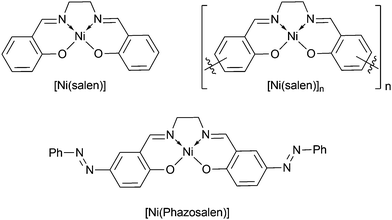 | ||
| Scheme 1 Structures of monomeric nickel complexes [Ni(salen)], [Ni(Phazosalen)] and polymer [Ni(salen)]n. | ||
Results and discussion
The starting nickel complex [Ni(Phazosalen)] was obtained by a known procedure via azo-coupling of phenyldiazonium chloride with salicylic aldehyde, followed by condensation of the resulting phenylazo-substituted aldehyde with ethylene diamine and subsequent metalation with nickel acetate.37[Ni(Phazosalen)] was electrochemically active in the 0.4–1.4 V range, showing an irreversible oxidation peak at 1.26 V, followed by an intense oxidation wave at higher potentials. To check the possibility of polymerization of [Ni(Phazosalen)] and to optimize the polymerization conditions, we performed repetitive voltage cycling with variable upper potential boundary (ESI,† Fig. SI1). The formation of polymer film was not observed when the monomer complex was subjected to voltage cycling in 0.4–1.1 V. Extension of the anodic range of the potential window (from 1.2 V to no more than 1.4 V) resulted in formation and steady growth of new anodic and cathodic peaks. This led to the formation of a new electroactive material on the electrode, arbitrarily denoted below as [Ni(Phazosalen)]n (ESI,† Fig. SI1).
It is known23,38 that the stability of nickel-salen based electrode materials drastically deteriorates if the material is kept at high anodic voltage. The same effect was observed when [Ni(Phazosalen)]n was deposited from solution by voltage cycling in 0.4–1.5 V (ESI,† Fig. SI1e). The film formed during the first few cycles lost the electrochemical activity almost entirely by the 10th cycle. For this reason, deposition of the new electrode material, [Ni(Phazosalen)]n, from [Ni(Phazosalen)] was performed in potentiostatic mode at the onset of [Ni(Phazosalen)] oxidation (1.2 V vs. Ag|AgCl) in all the experiments discussed below. Unlike cycling mode, the potentiostatic mode of electrochemical deposition allows for the control of the amount of charge used for polymer formation, ensuring reproducibility of the properties of the deposited films. Oxidative electrochemical deposition was performed from 1 mM solution of the starting complex in 1,2-dichloroethane (DCE) containing 0.1 M Bu4N+BF4− as the supporting electrolyte (ESI,† Fig. SI2), and the film thickness was controlled by maintaining a charge of 57 mC cm−2. Acetonitrile and propylene carbonate, usual solvents for electropolymerization of [Ni(salen)] complexes, could not be used due to very low solubility of [Ni(Phazosalen)] in these solvents. Hence, the commonly used Et4N+BF4− was substituted for Bu4N+BF4− to improve the solubility.
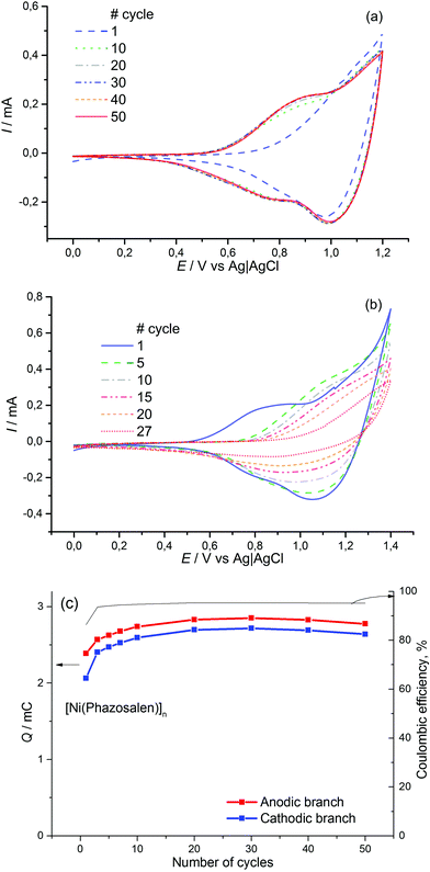
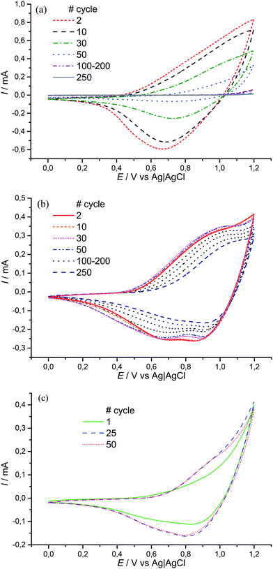
The obtained material is electrochemically active and stable in the range of 0–1.2 V, where two redox processes occur at E1/2 = 0.85 V (CH3CN/0.1 M Et4N+BF4−) and E1/2 > 1.1 V (Fig. 1). The value of the first redox potential is quite close to the halfwave potential of the oxidation of the benchmark material, [Ni(salen)]n (0.9 V). The redox processes in [Ni(Phazosalen)]n reach equilibrium by the 10th cycle of CVA and no loss in electrochemical activity is observed up to the 50th cycle. The Coulombic efficiency of this process is about 95%. The anodic cut-off potential of 1.2 V is not sufficient to fully observe the second oxidation process on the voltammogram. However, application of higher voltage up to 1.4 V leads to the appearance of irreversible anodic current and results in degradation of the material and significant loss of its electroactivity: the charge drops to 65% of the initial value by the 27th cycle.
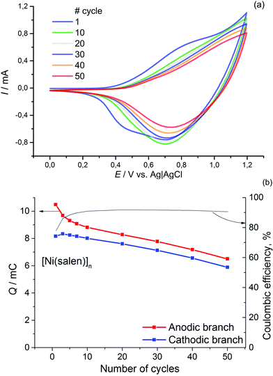
For comparison, similar data for [Ni(salen)]n are presented in Fig. 2. It can be observed that the films of the latter demonstrate lower stability (the electrochemical activity of these films dropped by 30% during 50 cycles of voltage cycling). The Coulombic efficiency of the [Ni(salen)]n charge–discharge process does not exceed 90%.
Electrochemical impedance spectroscopy (EIS) is known to be a reliable and informative method for studying the charge transport and storage in polymer films. Fig. 3 shows the complex plane impedance plots for [Ni(Phazosalen)]n and [Ni(salen)]n films constructed for the different potentials applied. The spectra of both polymers have a similar pattern. At high frequencies, semicircles are observed that correspond to RC element consisting of the double layer charging capacitance, Cdl, and charge transfer resistance, Rct, related to the heterogeneous kinetic process of electrochemical oxidation. At lower frequencies, two linear regions of the curve are observed. The linear region of 45° slope corresponds to the Warburg impedance, ZW, and is due to the diffusion of the counterions, while the linear region with slope close to 90° corresponds to the low frequency capacitance, Clf, which arises from charging of the polymer film of finite thickness.
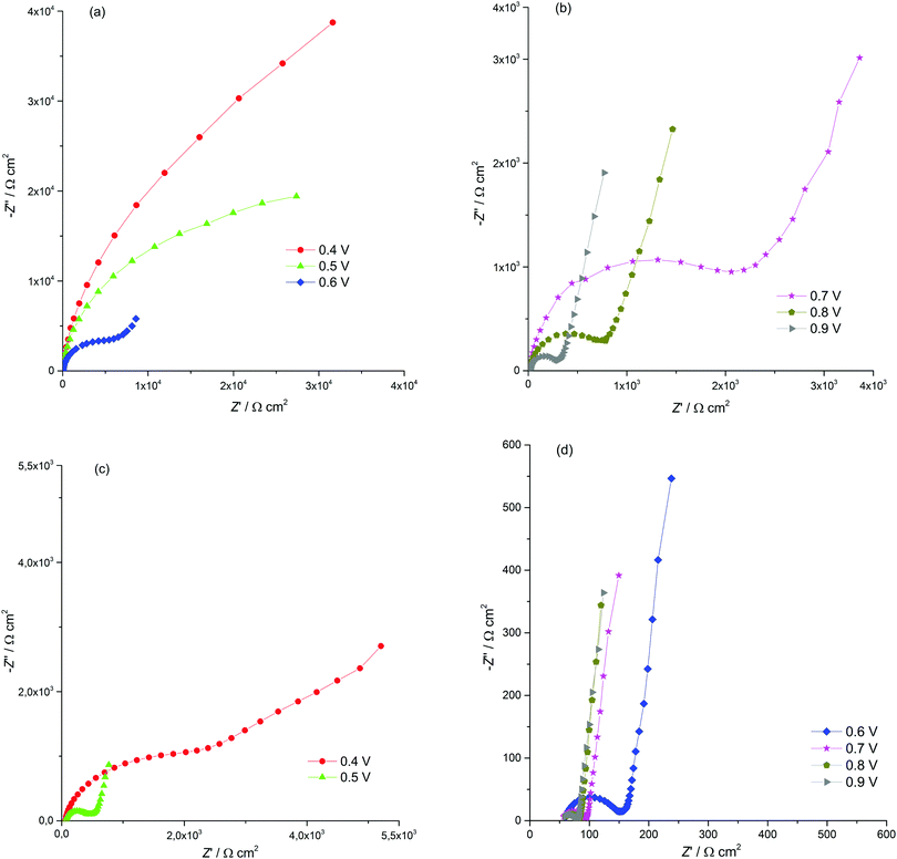 | ||
| Fig. 3 Nyquist plots for the ITO electrode coated with [Ni(Phazosalen)]n (a and b) and [Ni(salen)]n (c and d) films in 0.1 M (TEA)BF4, in acetonitrile, for different potentials applied. | ||
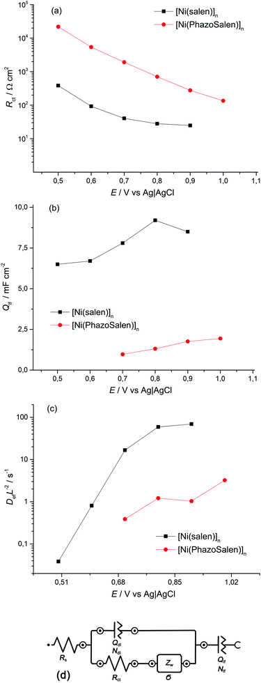
According to this pattern of the impedance spectra, they were simulated by a modified Randles–Ershler equivalent electric circuit.39 The elements of constant phase were introduced to the model instead of capacitance units to take into account non-uniform distribution of film thickness and their porous structure. The numerical values obtained after fitting of the spectra are shown in Fig. 4 and are summarized in Tables SIA1 and SIA2 (ESI†). As can be observed from these data, both polymers demonstrate an increase in the Warburg coefficient σ with increasing voltage, accompanied by a decrease in the charge transfer resistance. This testifies to the transition of the polymers to a more conducting state upon oxidation. It should be mentioned that Rct of the [Ni(Phazosalen)]n film is one order of magnitude higher than Rct of [Ni(salen)]n, testifying to the slower kinetics of electrochemical transformations in the former polymer. At the same time, the Warburg constant of [Ni(Phazosalen)]n is several orders of magnitude higher than that of [Ni(salen)]n. The effective diffusion coefficients, Def, of the charge carriers within the studied films can be determined by using a constraint between the Warburg constant and the low-frequency capacity using the following equation:40
Qualitative elemental analysis of [Ni(Phazosalen)]n was performed using the XPS technique. Thus, a characteristic Ni atom signal was observed as a pair of 2p3/2 and 2p1/2 peaks at 854.6 and 871.9 eV (Fig. SI4, ESI†), while signals of N and O atoms were observed at 399.7 and 530.5 eV, respectively (Fig. SI5 and S6, ESI†). The peaks positions are slightly (0.1–0.4 eV) shifted to higher energies compared to the monomer complex, reflecting the increase in binding energy of core electrons upon oxidative polymerization (Table 1). The satellite signals were not observed in the range of signals for Ni 2p electrons in both [Ni(Phazosalen)] and [Ni(Phazosalen)]n. According to literature reports,41,42 this testifies to the planar structure of Ni complexes in both cases. Interestingly, the chemical shift of Ni, N and O atoms (2p3/2(1/2), 1s and 1s, respectively) upon polymerization of [Ni(salen)] is significantly larger than in the case of [Ni(Phazosalen)] (0.6–0.7 vs. 0.1–0.4 eV). This could testify to the existence of different modes of connection of the monomer units in the respective polymers, with [Ni(Phazosalen)]n retaining more structural features of the starting monomer compared to [Ni(salen)]n.
| Compound | Ni(2p3/2) | Ni(2p1/2) | N(1s) | O(1s) |
|---|---|---|---|---|
| a ΔEb = Eb(polymer) − Eb(monomer). | ||||
| E b; ΔEb, eVa | ||||
| [Ni(salen)] | 854.3; — | 871.5; — | 398.4; — | 530.2; — |
| [Ni(Phazosalen)] | 854.3; — | 871.5; — | 398.6; — | 530.3; — |
| [Ni(salen)]n | 854.9; 0.6 | 872.2; 0.7 | 399.1; 0.7 | 530.2; 0.6 |
| [Ni(Phazosalen)]n | 854.6; 0.3 | 871.9; 0.4 | 398.7; 0.1 | 530.2; 0.2 |
In addition to Ni, N, O and C (284 eV) signals, a Cl signal was also observed in the XPS spectrum of [Ni(Phazosalen)]n around 200 eV (Fig. SI7, ESI†), but not in the spectrum of the starting monomer. Deconvolution of the experimental signal provided three Gaussians with maxima at 201.2, 199.7 and 197.8 eV. The last signal is typical of the chloride anion43 and could originate from the electrochemical decomposition of the solvent under experimental conditions. The first two signals are characteristic for arylchlorides, such as chlorobenzene,44,45 and witness chlorination of the starting [Ni(Phazosalen)] upon electrochemical oxidation in dichloroethane. Semi-quantitative elemental analysis based on the XPS data provides the following elemental composition for the obtained material: Ni (2.0%), C (74.9%), N (12.5%), O (8.7%), and Cl (1.9%). This corresponds to ca. 20–30 mol% of the chlorinated fragment (Table 2).
Functional group analysis of [Ni(Phazosalen)]n based on FTIR spectra confirmed that the material retains the key structural Phazosalen fragment. The band corresponding to C![[double bond, length as m-dash]](https://www.rsc.org/images/entities/char_e001.gif) N bond stretching appears at 1637 cm−1 in the starting imine. Upon complexation with Ni2+, this band shifts to 1620 cm−1, presumably due to increased rigidity of the structure resulting from the formation of a new cycle. Subsequent oxidative transformation upon deposition of the material shows little effect on this band (1624 cm−1). A Ni–N valence band46 is observed in [Ni(Phazosalen)] and [Ni(Phazosalen)]n at 534 cm−1.
N bond stretching appears at 1637 cm−1 in the starting imine. Upon complexation with Ni2+, this band shifts to 1620 cm−1, presumably due to increased rigidity of the structure resulting from the formation of a new cycle. Subsequent oxidative transformation upon deposition of the material shows little effect on this band (1624 cm−1). A Ni–N valence band46 is observed in [Ni(Phazosalen)] and [Ni(Phazosalen)]n at 534 cm−1.
The NMR study of [Ni(Phazosalen)] and [Ni(Phazosalen)]n was performed in TFA (trifluoroacetic acid) solutions due to the solubility of these compounds in this solvent, afforded by reversible protonation of nitrogen and oxygen atoms. This study confirmed that the main component of [Ni(Phazosalen)]n is the structurally intact [Ni(Phazosalen)]. The signals in the spectrum of the starting monomeric [Ni(Phazosalen)] are widened, probably due to the presence of paramagnetic species.‡ Nevertheless, the multiplicity and intensity provided unambiguous attribution. The multiplets at 8.2, 7.8 and 7.7 ppm correspond to monosubstituted phenyl rings at the azo group; the singlet at 8.7 ppm corresponds to H6, while the AB system at 8.5 and 7.4 ppm belongs to H3 and H4 (Fig. 5). These signals are better resolved in the spectrum of [Ni(Phazosalen)]n and account for 74 mol% of all azo-benzene fragments. The second component (22 mol%) shows almost the same pattern of signals, except the signal for H3, which is absent. It is possible to conclude from these data, that the minor component is a 3-substituted derivative. Additional proof is found in the fine structure of the signals for H4 and H6, which constitute an AB system at 8.83 and 8.65 ppm with a small coupling constant J of 2.5 Hz, typical for interaction of protons with meta-alignment. Combining these data with the results of XPS analysis, where chlorine atoms were observed, one can conclude that the minor component is the 3-chlorosubstituted derivative of the starting [Ni(Phazosalen)] complex. There are also trace amounts of an unidentified admixture of ca. 4 mol%.
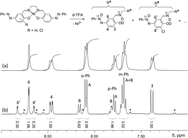 | ||
| Fig. 5 Aromatic proton region in the 1H NMR spectra of [Ni(Phazosalen)] (a) and [Ni(Phazosalen)]n (b) solutions in d-TFA; unidentified signals of minor components are marked with an asterisk. | ||
Taking into account the results of XPS, FTIR and NMR analyses, we concluded that [Ni(Phazosalen)]n, unlike [Ni(salen)]n, represents mostly stacked molecules of monomer complex [Ni(Phazosalen)] with minor inclusions of 3-chlorosubstituted derivatives (Fig. 5, R = Cl).
To determine the mode of stacking (π–d, π–π or d–d), we performed dispersion corrected DFT calculations (CAM-B3LYP-D3/6-31G* level of theory) on possible modes of arrangement of two monomer molecules in neutral and oxidized forms.
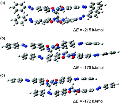
DFT calculations were carried out for dimers comprised of [Ni(salen)] and [Ni(Phazosalen)] neutral molecules and singly charged cations. The results of geometry optimization suggest the existence of a variety of structures, differing in the relative positions of the two molecules in the dimer. Three possible stack-like structures obtained for a system containing two [Ni(Phazosalen)] molecules with a total charge of +1 are shown in Fig. 6.
For the first of these structures (Fig. 6(a)) the line connecting the nickel atoms is almost perpendicular to the NNOO-planes of the Schiff-base ligands, i.e., the two molecules are not shifted relative to each other. Though such structures can be intuitively described as dimers with d–d-stacking, electronic structure analysis does not reveal significant bonding between the nickel atoms. However, this structure is the most stable of the three dimers shown in Fig. 6; its energy of formation (ΔE) (defined as the energy of the dimer minus the energies of neutral or charged monomers) being as low as −215 kJ mol−1. The energies of formation for two other [Ni(Phazosalen)]2+ structures (Fig. 6(b) and (c)) are higher by 36 and 43 kJ mol−1, respectively. In the former of these two structures, the [Ni(Phazosalen)] fragments remain almost parallel, but are shifted by about 3.2 Å relative to each other. This shift places the nickel atoms above or below the center of the aromatic rings of the salen fragment of the neighboring molecule. Furthermore, such a configuration of the dimer can be recognized as π–d-stacking, but a more detailed insight does not show significant electron density between the metal atom and the aromatic ring. Finally, in the last of the three structures (Fig. 6(c)), the molecules are shifted by ca. 3.9 Å; hence, the nickel atoms are located over N![[double bond, length as m-dash]](https://www.rsc.org/images/entities/char_e001.gif) N bonds without definite signs of bonding between them. Taking a closer look at the dependence of dimer stability on the shifting distance, one can observe an almost-linear change of ΔE with increasing separation of molecules. Such an effect is unlikely to be caused by differences in the nature of bonding between the molecules constituting the dimer (such as d–d or π–d-stacking interactions); this conclusion is readily supported by electronic structure analysis.
N bonds without definite signs of bonding between them. Taking a closer look at the dependence of dimer stability on the shifting distance, one can observe an almost-linear change of ΔE with increasing separation of molecules. Such an effect is unlikely to be caused by differences in the nature of bonding between the molecules constituting the dimer (such as d–d or π–d-stacking interactions); this conclusion is readily supported by electronic structure analysis.
The stability of the stack-like structures formed by [Ni(salen)] and [Ni(Phazosalen)] is strongly influenced by the total system charge and the nature of the ligand. As indicated by the computed ΔE values for ‘pseudo d–d-stacked’ structures similar to the one shown in Fig. 6(a), the formation of a dimer is energetically favorable only for systems with a total charge of 0 and +1. The most stable form of both [Ni(salen)]2q and [Ni(Phazosalen)]2q dimers is the one with a total charge of +1. The energy of formation for dimers with q = +2 is positive (Table 3), which is likely a result of strong Coulomb repulsion between two positively charged [Ni(salen)]+ or [Ni(Phazosalen)]+ species. Dimers with a total charge of 0 (two neutral molecules) or +1 (one cation and one neutral molecule) are stabilized by the very large contribution of dispersion forces (Edisp), which are represented by the Grimme's dispersion term in the density functional. This contribution is largely independent of the total charge, though it displays a small increase for oxidized dimers. The nickel–nickel distances, provided in Table 3, suggest that this effect can be explained by the decrease in the distance between the monomers. The comparison of ΔE values for [Ni(salen)] and [Ni(Phazosalen)] shows that all forms of [Ni(Phazosalen)]2q dimers are significantly more stable than the equivalent [Ni(salen)]2q species. Compared to [Ni(salen)], [Ni(Phazosalen)] dimers have significantly more negative Edisp values. Hence, the improved stability of [Ni(Phazosalen)]2q species is a result of the greater contribution of dispersion interactions, which is likely to increase with increase in the area of contact between the molecules in the dimer.
| Dimer | Property | Dimer charge q | ||
|---|---|---|---|---|
| q = 0 | q = +1 | q = +2 | ||
| [Ni(salen)]2q | r(Ni–Ni), Å | 3.27 | 3.10 | 3.04 |
| E disp, kJ mol−1 | −225 | −232 | −232 | |
| ΔE, kJ mol−1 | −127 | −171 | +129 | |
| [Ni(Phazosalen)]2q | r(Ni–Ni), Å | 3.28 | 3.17 | 3.17 |
| E disp, kJ mol−1 | −350 | −356 | −364 | |
| ΔE, kJ mol−1 | −158 | −215 | +34 | |
The theoretical results mentioned above are consistent with X-ray diffraction data for [Ni(salen)]47 and [Ni(Phazosalen)] (Fig. 7).
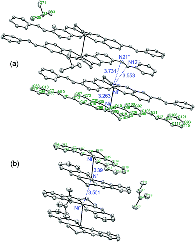 | ||
| Fig. 7 Comparison of the arrangement of [ML]2 intermolecular dimers in the crystal lattice of [Ni(Phazosalen)] (this work) and [Ni(salen)].47 | ||
Both these compounds are packed in a crystal in the dimeric species with a non-displaced arrangement: aryl rings atop aryl rings and metal above metal. Interestingly, the Ni–Ni distance in the [Ni(Phazosalen)] crystal is lower by 0.13 Å compared to the [Ni(salen)] crystal, testifying to the existence of additional attractive intermolecular forces due to increased π–π or dispersive interaction in the former case. Of special interest is the difference in the way the dimeric species are packed into the crystal in [Ni(salen)] and [Ni(Phazosalen)]. According to a literature report,47 the [Ni(salen)]2 species adopt a non-displaced arrangement in a crystal, with Ni–Ni′ distance being ca. 3.55 Å, suggesting no evidence for π–d interaction. Unlike this, the [Ni(Phazosalen)]2 species are displaced parallel with respect to one another, the Ni atom in one dimer opposing the N![[double bond, length as m-dash]](https://www.rsc.org/images/entities/char_e001.gif) N azo group of the adjacent dimer. The distances between Ni and N atoms are 3.55 and 3.73 Å, respectively. These data might be explained by Coulomb attraction of regions with positive electrostatic potential over metal atoms to the regions with negative electrostatic potential over the N
N azo group of the adjacent dimer. The distances between Ni and N atoms are 3.55 and 3.73 Å, respectively. These data might be explained by Coulomb attraction of regions with positive electrostatic potential over metal atoms to the regions with negative electrostatic potential over the N![[double bond, length as m-dash]](https://www.rsc.org/images/entities/char_e001.gif) N π-system (Fig. 8).
N π-system (Fig. 8).
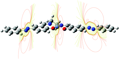 | ||
| Fig. 8 Electrostatic potential slices in [Ni(Phazosalen)] complex. Regions of positive ESP are in orange color, regions of negative ESP are in purple color. | ||
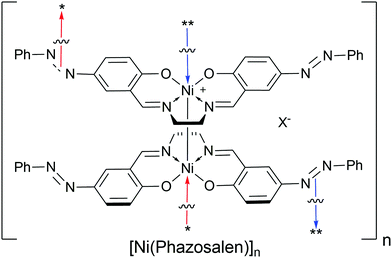
Thus, [Ni(Phazosalen)]n represents a “stacked material” consisting primarily of stacked molecules of the monomer complex [Ni(Phazosalen)] rather than a classical polymer (Scheme 2). The binding forces that keep the molecules in [Ni(Phazosalen)]n together include the dispersive interaction of the extended π-systems, the Coulomb attraction of metal atoms and azo groups and the Coulomb attraction of positively charged [Ni(Phazosalen)]+ monocations with counterions that compensate the positive charge.
The difference in polymer linkage nature compared to [Ni(salen)]n results in different morphology of the material. According to the SEM study of polymeric films of [Ni(salen)]n and [Ni(Phazosalen)]n on glass carbon support, [Ni(salen)]n, having a relatively flexible organic backbone, forms a globular material with globules of ca. 300 nm in diameter (Fig. 9). In contrast, [Ni(Phazosalen)]n, consisting of tight stacks of rigid monomers, forms a more homogenous laminated material (Fig. 9). This dense structure could be responsible for the low charge carrier diffusion coefficient observed by the impedance measurements. At the same time, the absence of C–C bonds between the [Ni(Phazosalen)] units indicates that, unlike [Ni(salen)]n, this material does not have the long π-conjugated system. This leads to the lack of charge transport pathways, which can be responsible for high charge transfer resistance of the [Ni(Phazosalen)]n material.
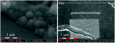 | ||
| Fig. 9 SEM microphotography of [Ni(salen)]n (a) and [Ni(Phazosalen)]n (b) films on glass carbon support. | ||
Interestingly, different structure and morphology resulted in increased electrochemical stability of [Ni(Phazosalen)]n compared to [Ni(salen)]n in the presence of water (Fig. 10). Thus, the addition of 1% water to an acetonitrile solution of 0.1 M Et4N+BF4−, while registering a CVA of [Ni(salen)]n film in the range of 0–1.2 V, resulted in 83% activity loss (measured as the acquired charge) by the 50th cycle. On the contrary, the [Ni(Phazosalen)]n film retained full activity by the 50th cycle. Repeating the measurement under open-to-air conditions resulted in 40.5% activity loss by the 250th cycle for [Ni(Phazosalen)]n; this is an excellent result for [Ni(salen)]-based materials, which are known to be moisture sensitive.16,17
In 0.1 M LiClO4 aqueous solution, there is no loss of activity for [Ni(Phazosalen)]n film in the potential range from 0 to 1.2 V (Fig. 10c and Fig. SI3a, ESI†). After increasing it to 1.3 V, the film loses only 9.5% of the initial activity by the 50th cycle (Fig. SI3b, ESI†). An increase of the upper boundary of the potential range to 1.4 V resulted in the quick loss of electrochemical activity by the film.
The observed moisture resistance of [Ni(Phazosalen)]n can be used for the creation of moisture resistant energy storage devices based on aqueous electrolytes, as well as other water-based devices such as electrochemical sensors. The specific capacitance of [Ni(Phazosalen)]n polymer material was determined by QCM measurements to be 120 F g−1. Although this value is two times less than the specific capacitance of [Ni(salen)]n due to the higher molecular weight of the [Ni(Phazosalen)] fragment, the superior stability of the new material is a substantial advantage.
Conclusions
To conclude, we have synthesized a new electrode material from the [Ni(salen)] family. The material bears phenylazogroup in the p-position with respect to the oxygen atom in the salen-ligand core, preventing the usual polymerization of [Ni(salen)] complexes via oxidative coupling of the phenyl rings. Instead, the complex molecules are held together by dispersive and ionic interactions. The material obtained exhibits excellent moisture resistance and can be applied in the creation of water resistant electrode materials for energy storage or sensor applications.Experimental
Materials and methods
[Ni(Phazosalen)]n was electrochemically deposited from 1 mM solution [Ni(Phazosalen)] in 0.1 M solution Bu4NBF4 in 1,2-dichloroethane. Electrochemical deposition was performed in a three-electrode cell on ITO or glass-carbon support as a working electrode, Pt plate as a counter electrode and BASi MF-2062 Ag|Ag+ (Ag wire immersed in acetonitrile containing 0.1 M AgNO3) as a reference electrode. The potential of the latter was found to comprise +0.40 V vs. Ag|AgCl (aqueous saturated KCl) reference electrode. All potentials throughout the text are recalculated vs. an aqueous Ag|AgCl electrode. The deposition was realized in potentiostatic mode with an applied bias of 1.2 V. The bias was applied until the consumption of 57 mC cm−2 was achieved.
Spectra of the samples were recorded in the constant pass energy mode at 20 eV, using a 650 micron diameter analysis area. During data processing of the XPS spectra, the binding energy values were referenced to the C 1s peak (284.8 eV) from the adventitious contamination layer. Investigations were carried out at room temperature in an ultrahigh vacuum of the order of 1 × 10⁻⁹ mbar. The AVANTAGE software package was used for acquisition and data analysis.
Unconstrained geometry optimizations were carried out for dimers consisting of two [Ni(salen)] or [Ni(Phazosalen)] complexes; the optimized structures were verified by vibrational frequency analysis.
Conflicts of interest
There are no conflicts to declare.Acknowledgements
The work was supported by the Russian Science Foundation (grant #16-13-00038). Scientific research was partially performed at the Research park of St. Petersburg State University: Interdisciplinary Center for Nanotechnology, Center for Chemical Analysis and Materials Research, Chemistry Educational Centre, Magnetic Resonance Research Centre, Centre for X-ray Diffraction Studies, Computing Centre X-ray Diffraction Studies, Computing Centre, Center for Studies in Surface Science.Notes and references
- F. Gao, J. Li, F. Kang, Y. Zhang, X. Wang, F. Ye and J. Yang, J. Phys. Chem. C, 2011, 115, 11822 CAS.
- M. P. Karushev and A. M. Timonov, Russ. J. Appl. Chem., 2012, 85, 914 CrossRef CAS.
- J. L. Li, F. Gao, Y. K. Zhang, F. Y. Kang, X. D. Wang, F. Ye and J. Yang, Sci. China: Chem., 2012, 55, 1338 CrossRef CAS.
- J. Tedim, F. Goncalves, M. F. R. Pereira, J. L. Figueiredo, C. Moura, C. Freire and A. R. Hillman, Electrochim. Acta, 2008, 53, 6722 CrossRef CAS.
- Y. Zhang, J. Li, F. Gao, F. Kang, X. Wang, F. Ye and J. Yang, Electrochim. Acta, 2012, 76, 1 CrossRef CAS.
- G. Yan, J. Li, Y. Zhang, F. Gao and F. Kang, J. Phys. Chem. C, 2014, 118, 9911 CAS.
- J. Tedim, R. Bessada, S. Patricio, A. L. Magalhaes, C. Freire, S. J. Gorman and A. R. Hillman, Langmuir, 2008, 24, 8998 CrossRef CAS PubMed.
- O. F. Filho, E. R. Dockal, L. Humberto, M. Junior and M. F. S. Teixeira, Anal. Lett., 2007, 40, 1825 CrossRef.
- C. S. Martin, T. R. L. Dadamos and M. F. S. Teixeira, Sens. Actuators, B, 2012, 175, 111 CrossRef CAS.
- V. T. Avanesyan and M. Y. Puchkov, Phys. Solid State, 2009, 51, 2178 CrossRef CAS.
- S. A. Krasikova, M. A. Besedina, M. P. Karushev, E. A. Dmitrieva and A. M. Timonov, Russ. J. Electrochem., 2010, 46, 218 CrossRef CAS.
- M. Nunes, M. Araujo, J. Fonseca, C. Moura, R. Hillman and C. Freire, ACS Appl. Mater. Interfaces, 2016, 8, 14231 CAS.
- L. Gomes, C. Sousa, C. Freire and B. de Castro, Acta Crystallogr., Sect. C: Cryst. Struct. Commun., 2000, 56, 1201 Search PubMed.
- M. Vilas-Boas, I. C. Santos, M. J. Henderson, C. Freire, A. R. Hillman and E. Vieil, Langmuir, 2003, 19, 7460 CrossRef CAS.
- J. Tedim, A. Carneiro, R. Bessada, S. Patricio, A. L. Magalhaes, C. Freire, S. J. Gurman and A. R. Hillman, J. Electroanal. Chem., 2007, 610, 46 CrossRef CAS.
- P. Audebert, P. Capdevielle and M. Maumy, New J. Chem., 1992, 16, 697 CAS.
- C. S. Martin, C. Gouveia-Caridade, F. N. Crespilho, C. J. L. Constantino and C. M. A. Brett, Electrochim. Acta, 2015, 178, 80 CrossRef CAS.
- I. A. Chepurnaya, P. V. Gaman'kov, T. Yu. Rodyagina, S. V. Vasil'eva and A. M. Timonov, Russ. J. Electrochem., 2003, 39, 314 CrossRef CAS.
- S. V. Vasil'eva, K. P. Balashev and A. M. Timonov, Elektrokhimiya, 1998, 34, 1090 Search PubMed.
- M. P. Karushev, Mechanisms of polymerization and charge transport in polymer complexes of nickel with Schiff bases, PhD thesis, Herzen State Pedagogical University of Russia, St. Petersburg, 2012 Search PubMed.
- K. A. Goldsby, J. K. Blaho and L. A. Hoferkamp, Polyhedron, 1989, 8, 113 CrossRef CAS.
- J. Tedim, S. Patrício, J. Fonseca, A. L. Magalhães, C. Moura, A. R. Hillman and C. Freire, Synth. Met., 2011, 161, 680 CrossRef CAS.
- M. Vilas-Boas, C. Freire, B. De Castro, P. A. Christensen and A. R. Hillman, Inorg. Chem., 1997, 36, 4919 CrossRef CAS.
- C. E. Dahm, D. G. Peters and J. Simonet, J. Electroanal. Chem., 1996, 410, 163 CrossRef.
- G. Shagisultanova, I. Orlova, L. Ardasheva and E. Popova, Macromol. Symp., 1998, 136, 91 CrossRef CAS.
- M. Martins, M. Vilas-Boas, B. de Castro, A. R. Hillman and C. Freire, Electrochim. Acta, 2005, 51, 304 CrossRef CAS.
- P.-H. Aubert, A. Neudeck, L. Dunsch, P. Audebert, P. Capdevielle and M. Maumy, J. Electroanal. Chem., 1999, 470, 77 CrossRef CAS.
- M. Vilas-Boas, M. J. Henderson, C. Freire, A. R. Hillman and E. Vieil, Chem. – Eur. J., 2000, 6, 1160 CAS.
- M. Vilas-Boas, C. Freire, B. De Castro, P. A. Christensen and A. R. Hillman, Chem. – Eur. J., 2001, 7, 139 CrossRef CAS.
- B. Bag, N. Mondal, G. Rosair and S. Mitra, Chem. Commun., 2000, 1729 RSC.
- O. Rotthaus, O. Jarjayes, F. Thomas, C. Philouze, C. P. D. Valle, E. Saint-Aman and J. L. Pierre, Chem. – Eur. J., 2006, 12, 2293 CrossRef CAS PubMed.
- O. Rotthaus, F. Thomas, O. Jarjayes, C. Philouze, E. Saint-Aman and J. L. Pierre, Chem. – Eur. J., 2006, 12, 6953 CrossRef CAS PubMed.
- L. A. Hoferkamp and K. A. Goldsby, Chem. Mater., 1989, 1, 348 CrossRef CAS.
- T. Storr, E. C. Wasinger, E. C. Pratt and R. C. Stack, Angew. Chem., Int. Ed., 2007, 46, 5198 CrossRef CAS PubMed.
- R. M. Clarke, K. Herasymchuk and T. Storr, Coord. Chem. Rev., 2017, 352, 67 CrossRef CAS.
- Y. Shimazaki, F. Tani, K. Fukui, Y. Naruta and O. Yamauchi, J. Am. Chem. Soc., 2003, 125, 10512 CrossRef CAS PubMed.
- W.-S. Han, H.-J. Lee, J.-S. Lee, Y.-H. Lee and T.-K. Hong, J. Anal. Chem., 2014, 69, 187 CrossRef CAS.
- L. P. Ardasheva, G. V. Vovk, L. G. Pchelova and G. A. Shagisultanova, Russ. J. Appl. Chem., 2004, 77, 1962 CrossRef CAS.
- Z. Q. Gao, C. Kvarnström and A. Ivaska, Electrochim. Acta, 1994, 39, 1419 CrossRef CAS.
- O. V. Levin, M. P. Karushev, A. M. Timonov, E. V. Alekseeva, Sh. Zhangac and V. V. Malev, Electrochim. Acta, 2013, 109, 153 CrossRef CAS.
- L. J. Matienzo, L. I. Yin, S. O. Grim and W. E. Swartz, Inorg. Chem., 1973, 12, 2762 CrossRef.
- L. Chiang, K. Herasymchuk, F. Thomas and T. Storr, Inorg. Chem., 2015, 54, 5970 CrossRef CAS PubMed.
- H. Konno and Y. Yamamoto, Bull. Chem. Soc. Jpn., 1987, 60, 2561 CrossRef.
- D. T. Clark, D. Kilcast and W. K. R. Musgrave, J. Chem. Soc. D Chem. Commun., 1971, 516b RSC.
- D. T. Clark, D. Kilcast, D. B. Adams and W. K. R. Musgrave, J. Electron Spectrosc. Relat. Phenom., 1975, 6, 117 CrossRef CAS.
- J. Liu, B. Wu, B. Zhang and Y. Liu, Turk. J. Chem., 2006, 30, 41 CAS.
- M. Lutz, Acta Crystallogr., Sect. E: Struct. Rep. Online, 2003, 59, 950 Search PubMed.
- M. J. Frisch, G. W. Trucks, H. B. Schlegel, G. E. Scuseria, M. A. Robb, J. R. Cheeseman, G. Scalmani, V. Barone, G. A. Petersson, H. Nakatsuji, X. Li, M. Caricato, A. Marenich, J. Bloino, B. G. Janesko, R. Gomperts, B. Mennucci, H. P. Hratchian, J. V. Ortiz, A. F. Izmaylov, J. L. Sonnenberg, D. Williams-Young, F. Ding, F. Lipparini, F. Egidi, J. Goings, B. Peng, A. Petrone, T. Henderson, D. Ranasinghe, V. G. Zakrzewski, J. Gao, N. Rega, G. Zheng, W. Liang, M. Hada, M. Ehara, K. Toyota, R. Fukuda, J. Hasegawa, M. Ishida, T. Nakajima, Y. Honda, O. Kitao, H. Nakai, T. Vreven, K. Throssell, J. A. Montgomery, Jr., J. E. Peralta, F. Ogliaro, M. Bearpark, J. J. Heyd, E. Brothers, K. N. Kudin, V. N. Staroverov, T. Keith, R. Kobayashi, J. Normand, K. Raghavachari, A. Rendell, J. C. Burant, S. S. Iyengar, J. Tomasi, M. Cossi, J. M. Millam, M. Klene, C. Adamo, R. Cammi, J. W. Ochterski, R. L. Martin, K. Morokuma, O. Farkas, J. B. Foresman and D. J. Fox, Gaussian 09, Revision E.01, Gaussian, Inc., Wallingford CT, 2015 Search PubMed.
- T. Yanai, D. Tew and N. Handy, Chem. Phys. Lett., 2004, 393, 51 CrossRef CAS.
- S. Grimme, J. Antony, S. Ehrlich and H. Krieg, J. Chem. Phys., 2010, 132, 154104 CrossRef PubMed.
- P. J. Hay and W. R. Wadt, J. Chem. Phys., 1985, 82, 299 CrossRef CAS.
- S. F. Boys and F. Bernardi, Mol. Phys., 1970, 19, 553 CrossRef CAS.
- R. D. Dennington II, T. A. Keith and J. M. Millam, GaussView, Version 5.0.9, Semichem Inc., Shawnee Mission, KS, 2009 Search PubMed.
Footnotes |
| † Electronic supplementary information (ESI) available: Additional data on electrochemical and XPS studies, computational data, X-ray CIF-file. CCDC 1543618. For ESI and crystallographic data in CIF or other electronic format see DOI: 10.1039/c7nj03526h |
| ‡ According to the works of F. Thomas,31,32 [Ni(salen)] complexes are prone to oxidation with the formation of ligand radical species. Formation of trace amounts of such radical species might be the reason for the observed paramagnetic widening of the signals of the monomer [Ni(Phazosalen)] complex. |
| This journal is © The Royal Society of Chemistry and the Centre National de la Recherche Scientifique 2017 |

