
Computational model of inductively coupled plasma sources in comparison to experimental data for different torch designs and plasma conditions. Part II: theoretical model†
M.
Voronov
 *a,
V.
Hoffmann
b,
W.
Buscher
a and
C.
Engelhard
c
*a,
V.
Hoffmann
b,
W.
Buscher
a and
C.
Engelhard
c
aUniversity of Münster, Institute of Inorganic and Analytical Chemistry, Corrensstrasse 30, D-48149 Münster, Germany. E-mail: VoronovMV@mail.ru
bIFW Dresden, Institute for Complex Materials, P. O. Box 270116, D-01171 Dresden, Germany
cUniversity of Siegen, Department of Chemistry and Biology, Adolf-Reichwein-Str. 2, D-57076 Siegen, Germany
First published on 5th December 2016
Abstract
This computational study present a LTE-based model (LTE: local thermodynamic equilibrium) and a two-temperature model of an inductively coupled plasma (ICP) operated in a standard Fassel-type torch. In addition, a computational model for a low-argon-flow torch, which consumes only 0.6 L min−1 of Ar, is presented for the first time. The latter is a special modification of the ICP torch, where the Ar cooling gas stream is replaced by an outer stream of compressed air. The two models include a comprehensive simulation of torch wall temperature as well as tangential Ar flow inside the torches. It can also be applied to other new geometries of ICP torches. Plasma properties in both torches are simulated over a wide range of operational parameters. The models are validated by comparing the simulated electrical and internal ICP properties to experimental data.
1 Introduction
This work is a continuation of Part I,1 and presents ICP models, which are well supported by experimental data with different torch geometries and plasma conditions. A computational model of the SHIP torch is presented for the first time. It is assumed that the model will be used in the future for computational optimization of ICP torches. This part (Part II) of the study focuses on the computational model.A short review of the experimental developments of different ICP torches is given in our complementary article.1 The literature review revealed that ICP source developments were mainly based on empirical studies. After many years of experimental optimization, it is assumed that further improvements of existing and new torches will require numerical calculations of the ICP to model. This will help to study processes/effects that are not well understood and to optimize torch construction accordingly. Today, a 2D axially symmetric ICP model is well established, which is based on the publications by Mostaghimi, Proulx, Boulus, Barnes, et al.2–6 and assumes Local Thermodynamic Equilibrium (LTE) conditions. This model was further enhanced for multi-element simulations in the ICP,7 and simulations of solid nanoparticles transport and evaporation in the ICP.8 Also, a so-called two-temperature model was reported,9–11 in which the temperature of electrons is treated differently from the temperature of heavy particles. The boundary conditions for Maxwell equations, which describe the electro-magnetic fields in the ICP, are well formulated using an extended field approach.12,13 Additionally, there are simulations of the liquid sample introduction into the ICP,14–20 ICP in He atmosphere,21,22 simulations of the turbulence23,24 and three-dimensional structure25,26 of the ICP, as well as computational investigations of different ICP parameters.27–30 These works simulate the ICP in a standard torch at optimal parameters, some particular phenomena in the ICP, or investigate the influence of a limited number of parameters on the ICP properties.
In this article, we focus on two models of the ICP, which were developed to investigate plasma properties and to use them for future optimization of the torch geometries. One model is based on the LTE approach; the other one is a two-temperature model, which was implemented to check for possible deviations from LTE. A detailed description of the models and a comparison of their results with experimental data from plasma diagnostics (electrical properties31 and internal properties measured by optical emission spectrometry (OES) methods1) are presented here for a wide range of conditions with both standard and SHIP torch (simulated for the first time). Our models extend the previous simulations of the ICP introducing the following features: (1) models are applied for both SHIP and standard ICP torches and are also applicable to other ICP geometries. (2) Until now, the temperature inside the torch walls was simplified by using room temperature boundary conditions in the outer surface layer of the walls2–5 or simulated by applying a heating coupled boundary condition from FLUENT.7,8,27–30 In fact, the radiation loss of the heated walls was never taken into account. However, simulation of the wall temperature was not necessary in these models because the torch walls are not heated extremely in Fassel-type torches. In the present study, such a model is developed, which can be applied for practical optimization of torches. Particularly, variations of geometrical or electrical parameters should predict torch heating to avoid melting. The model is applied to simulate the SHIP torch, which features walls with higher temperature than usual. Therefore, calculation of temperature inside the torch walls is included in the model. This will provide the possibility to also optimize the cooling of the torches by simulations in the future. (3) Typically, the gas flow is introduced tangentially into ICP torches. The tangential component of the gas velocity is included in many models2–5 but not taken into account in other simulations.7,8,27–30 To clarify the influence of the tangential flow, special attention is paid to the ICP swirl gas flow in this work.
The liquid sample introduction (i.e., wet aerosol) is not yet included in the model discussed here. Nevertheless, results of the model are compared with different plasma temperatures, which were measured by optical methods1 based on radiation of the sample (OH and Fe spectral lines) in the plasma. Therefore, theoretical and experimental data should be interpreted cautiously.
Note that the used ICP instrument has an axially oriented optical interface equipped with a counter argon gas flow (Spectro CIROSCCD, Kleve, Germany), which is situated in the optical axis of the ICP. The optical interface is introduced in the model, too. In principle, all results and conclusions presented here are valid only for this special instrumental setup (see experimental setup of Part I for details). But general tendencies can also be extrapolated also to other commercial ICP excitation sources.
2 Description of the models
Both models are applied to two different ICP torches. The first one is the standard Fassel-type ICP torch, which is typically used for routine analysis with a Spectro CIROS ICP-OES instrument. The second one is the SHIP torch. The geometry of the torches is depicted in Fig. 1. The dimensions and optimal operational conditions of the torches are presented in Table 1.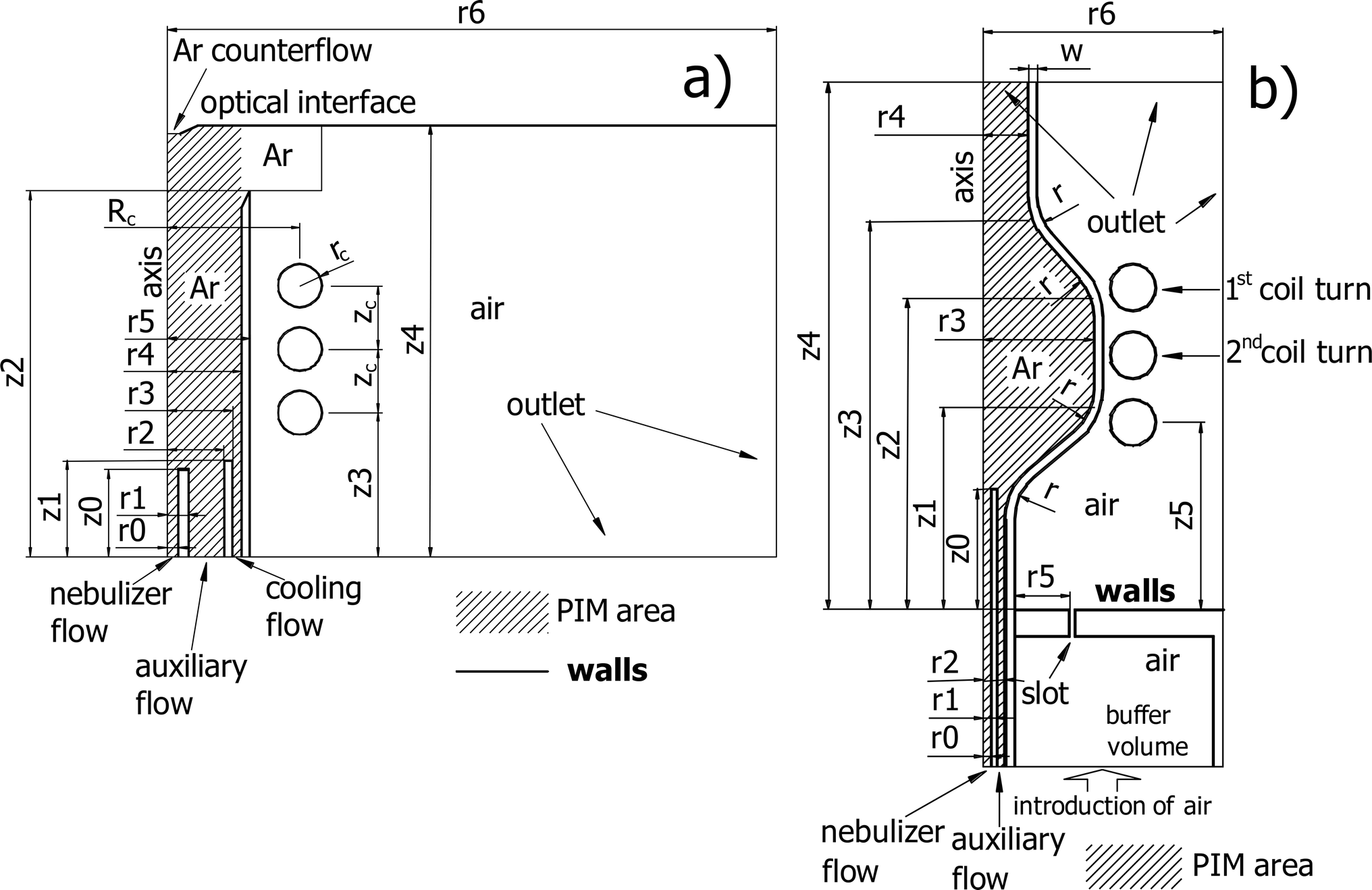 | ||
| Fig. 1 Geometry of standard (a) and SHIP (b) torches. | ||
| Standard torch | |||
| r 0 = 1.25 mm | r 1 = 2.5 mm | z 0 = 10 mm | r 2 = 6.5 mm |
| r 3 = 7.5 mm | z 1 = 11 mm | r 4 = 8.5 mm | r 5 = 9.5 mm |
| z 2 = 42 mm | R c = 15.25 mm | r c = 2.5 mm | z c = 7.3 mm |
| z 3 = 16.5 mm | r 6 = 70 mm | z 4 = 49.5 mm | |
| Ar nebulizer flow = 1 L min−1 | Ar auxiliary flow = 1 L min−1 | ||
| Ar cooling flow = 12 L min−1 | Ar counterflow = 0.6 L min−1 | ||
| rf frequency = 27.12 MHz | Measured plasma power W = 1150 W | ||
![[thin space (1/6-em)]](https://www.rsc.org/images/entities/char_2009.gif) |
|||
| SHIP torch | |||
| r 0 = 0.4 mm | r 1 = 1 mm | z 0 = 13 mm | r 2 = 1.4 mm |
| z 1 = 21 mm | r 3 = 11 mm | z 2 = 34 mm | z 3 = 42 mm |
| r 4 = 3.9 mm | z 4 = 57 mm | w = 1 mm | r = 6 mm |
| r 5 = 3.6 mm | r 6 = 25 mm | z 5 = 2.2 mm | |
| The load coil configuration is similar to the coil with the standard torch | |||
| Ar nebulizer flow = 0.4 L min−1 | Ar auxiliary flow = 0.2 L min−1 | ||
| Air cooling flow = 245 L min−1 | Input air pressure = 5 bar | ||
| rf frequency = 27.12 MHz | Measured plasma power W = 750 W | ||
The following assumptions were made during the development of the models, which are well-established in ICP modeling and used earlier for similar models:2–9 (1) the plasma torches and the load coil are modeled by a fully axisymmetric configuration. Therefore, distribution of temperatures, velocities and electro-magnetic fields are two-dimensional. (2) Steady state, laminar Ar and air flow at atmospheric pressure is assumed, including tangential gas flows. (3) The plasma is electrically neutral. (4) Displacement currents in the plasma are negligible. (5) The relative permeability of the torch walls is equal to one. (6) The plasma is considered as optically thin.
The following input parameters are required to use the models: the geometry of the torches and the gas flow rates, the electrical current in the load coil or the power consumed by the plasma. The results of the model are distributions of Ar and air density and velocity, distribution of temperature in Ar, air and quartz (material of the torch walls), distribution of electron temperature for the two-temperature model, electrical current in the coil (if the plasma power is set up in the input parameters) or plasma power (if the coil current is set up in the input parameters).
The models in this work are based on a modular structure. The electro-magnetic module (EMM) is used for calculation of electro-magnetic fields, the fluid kinetics module (FKM) is used for simulation of gas dynamics, and the plasma ionization module (PIM) is used to simulate the degree of ionization of the plasma and related electrical properties. The implementation of the PIM module for the LTE and two-temperature models is different because there are different models of ionization in a plasma (see below for details). The EMM and FKM are similar in both models used below. All the three modules are combined in different ways to implement the algorithms. The EMM and PIM modules are developed in a Pascal-family programming language (Oberon, compiler XDS, Excelsior, Novosibirsk, Russia). A commercial program “COMSOL Multiphysics” (version 4.3b, COMSOL AB, Burlington, USA) was used to develop the FKM.
The EMM calculates the distribution of electro-magnetic fields using Maxwell equations and uses two input parameters. The first one is the distribution of electrical conductivity of the plasma σ(![[r with combining right harpoon above (vector)]](https://www.rsc.org/images/entities/i_char_0072_20d1.gif) ) as function of the radius vector . The second parameter is either the electrical current in the coil Icoil or the power consumed by the plasma W. More details on the EMM can be found in Appendix A. The output of the EMM are the plasma power W (if Icoil is used as an input parameter) or the current in the coil Icoil (in the opposite case), the distribution of electro-magnetic fields, the density of power P(), which is resistively consumed by charged particles, and the density of Lorentz force
) as function of the radius vector . The second parameter is either the electrical current in the coil Icoil or the power consumed by the plasma W. More details on the EMM can be found in Appendix A. The output of the EMM are the plasma power W (if Icoil is used as an input parameter) or the current in the coil Icoil (in the opposite case), the distribution of electro-magnetic fields, the density of power P(), which is resistively consumed by charged particles, and the density of Lorentz force ![[F with combining right harpoon above (vector)]](https://www.rsc.org/images/entities/i_char_0046_20d1.gif) (), which affects the charged particles.
(), which affects the charged particles.
The FKM solves Navier–Stokes and heat transfer equations to simulate dynamics of the gas. The FKM uses the following input parameters: geometry of the plasma torch, values of the input gas flows applied as boundary conditions; atmospheric pressure at 1013 hPa. Other input parameters are density of power PFKM() and density of Lorentz forces FKM(), which are used as heat and force source applied to the gas, respectively. In both the LTE and the two-temperature models the Lorentz forces resulting from the EMM are directly used as input parameter for the FKM: FKM() = (). However PFKM() is introduced in the FKM in different ways (see description of the models below). The output of FKM are distributions of the temperature T() and gas velocity ![[small nu, Greek, vector]](https://www.rsc.org/images/entities/i_char_e0ea.gif) gas(). In contrast to the previous models, temperature inside the torch walls is comprehensively simulated. Therefore, T is either the gas temperature Tgas or the wall temperature Twall, depending on .
gas(). In contrast to the previous models, temperature inside the torch walls is comprehensively simulated. Therefore, T is either the gas temperature Tgas or the wall temperature Twall, depending on .
Important parameters of the FKM are the dynamic properties of gas: mean molar mass, thermal conductivity, thermal capacity, and viscosity. It is assumed in the model that 100% Ar is situated inside the torches, and 100% air is outside (see Fig. 1). Therefore, the corresponding properties of air, which are built-in to the COMSOL program, are used in the model outside of the torches. A more complex description of the gas dynamic properties is necessary for Ar. Because the ICP has a high degree of ionization, these parameters depend strongly on density and temperature of the electrons and on the composition of the gas. These parameters are calculated using a multi-element model proposed by Lindner et al.,7 where a gas-kinetic approach is employed for their description. More details can be found in Appendix B. These parameters are incorporated into the COMSOL program as function of T.
Power introduced into the plasma is dissipated to the plasma gas, then removed from the plasma volume by the Ar flow and transferred outside through the torch walls. In addition, the hot plasma loses energy by radiation. In case of the LTE model, the density of radiation loss32R(T) is additionally incorporated in the FKM. The two-temperature model takes this term into account in PIM rather than in FKM (see details below).
In the model of the standard ICP torch, four input gas flows are used (see Fig. 1a): cooling, auxiliary, and nebulizer gas flows, and an additional Ar counterflow, which flows in the used ICP instrument (Spectro CIROS) from an optical interface (OPI) in the opposite direction of the main gas flows. Here, typical gas flow rates are used as boundary conditions (see Table 1) for the Navier–Stokes equations together with the initial gas temperature of 293.15 K. Other boundary conditions include gas = 0 at the walls of the ICP torch and OPI. The walls of OPI are assumed to be at room temperature. Temperature of the walls of the torch is comprehensively calculated. At the far end of the chamber there is a gas outlet (see Fig. 1a). Here, the following boundary conditions are specified: the pressure of gas is 1013 hPa, there is no viscous stress, ![[n with combining right harpoon above (vector)]](https://www.rsc.org/images/entities/i_char_006e_20d1.gif) ∇T = 0, where is the unity vector, which is normal to the boundary.
∇T = 0, where is the unity vector, which is normal to the boundary.
In the SHIP torch model, a relatively large flow of cooling air has to be considered, which complicates the solution significantly. Therefore, a simpler geometry is used in the SHIP model (see Fig. 1b). Known values of Ar auxiliary and sample flows at room temperature are used as boundary conditions (see Table 1). In the gas outlet (see Fig. 1b) there are similar boundary conditions as in the outlet of the standard ICP torch. The cooling air in the model is introduced in a buffer volume (see Fig. 1b), which exists also in the experimental assembly (torch fastening device with cooling gas flow feed). Then the air flows from the buffer volume towards the outer surface of the torch through a thin cylindrically symmetrical slot (see Fig. 1b). The input boundary conditions of air are input pressure and room temperature at the boundary of the buffer volume. The buffer pressure was measured experimentally (3–7 bar, 5 bar at optimal conditions) and is used as input parameter of the model.
In the model, air flows from the buffer volume towards the outer surface of the torch through a slot (see Fig. 1b). There is however a difference in the experimental setup: in the experiment air flows through eight round nozzles that are incorporated in the torch-fastening device. The diameter of each nozzle is 1 mm. The nozzles are substituted in the model by a slot because of the cylindrical symmetry requirement. The area of the slot in the model is equal to the total area of all nozzles. The total flow of air is measured and compared in Fig. 2 with the calculated flow of air through the slot. A good agreement is observed in this figure indicating that the introduction of the air is simulated correctly.
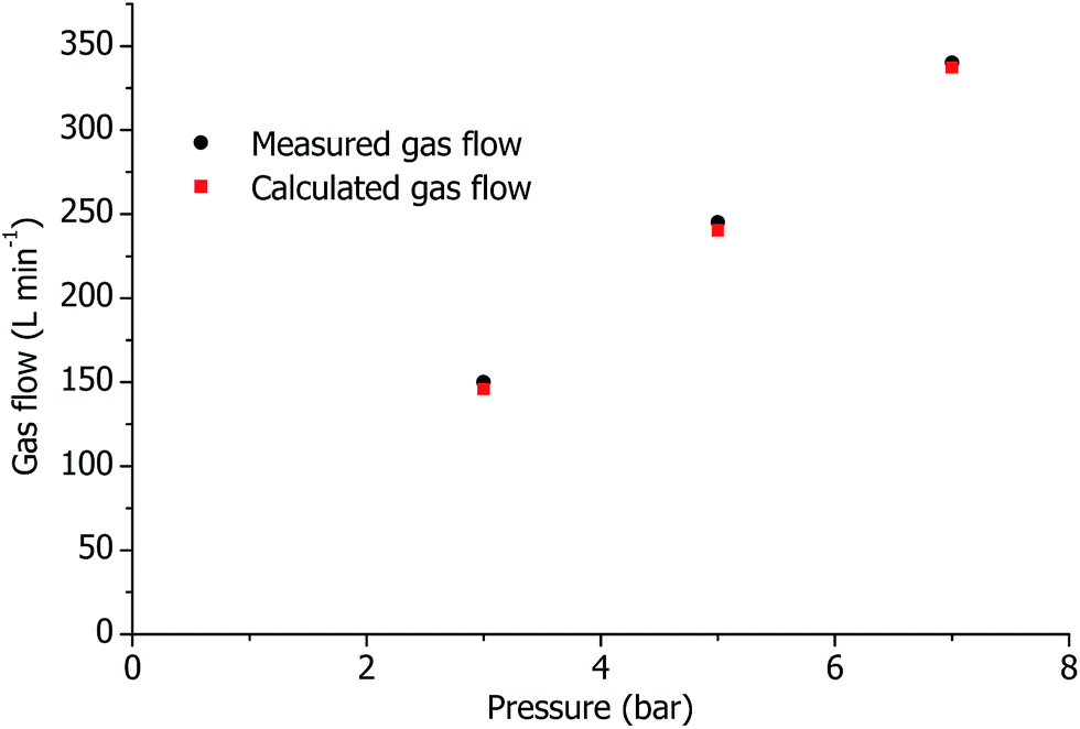 | ||
| Fig. 2 Calculated flow through the slot (see Fig. 1b) and measured total flow of air with SHIP torch. Except the air flow, all other parameters are optimal. | ||
2.1 The LTE model
The model is based on the LTE models of the ICP, which were originally developed by Mostaghimi, Proulx, Boulus, Barnes, et al.,5,6 and then modified and improved in numerous further works.7–30 The flow chart of the simulations used here is presented in Fig. 3a.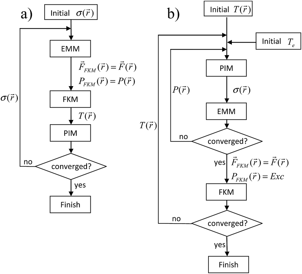 | ||
| Fig. 3 Flow-charts of the LTE (a) and two-temperature (b) models. | ||
In PIM, the degree of ionization and the electron number density are calculated using the Saha equation taking into account neutral, singly and doubly ionized Ar atoms. This model is described in details by Zaghloul et al.33,34 and was used by Lindner et al.7 for simulations of an ICP in an Ar/He mixture. The PIM module uses T() as input parameter. The results of the PIM are electron number density and electrical conductivity of the plasma σ(), which is calculated by a gas-kinetic approach (see Appendix B for details). Here, the PIM is applied only for Ar inside the torch, as indicated in Fig. 1a.
EMM, FKM, and PIM are applied one by one until convergence is reached. P() is applied to the FKM directly for gas heating: PFKM() = P(). For the 1st iteration, any reasonable distribution of the electrical conductivity σ0() can be set up. Therefore σ0() = 2500 ohm−1 m−1 within the PIM area was used, which is thought to be a corresponding value at 10000 K gas temperature.12
2.2 The two-temperature model
The model is based on works of Mostaghimi et al.9,10 Here, an electron temperature Te is introduced separately from Tgas. P() is applied for Joule heating of the electrons in the model. For this, an equation of thermal conductivity of electrons is solved:10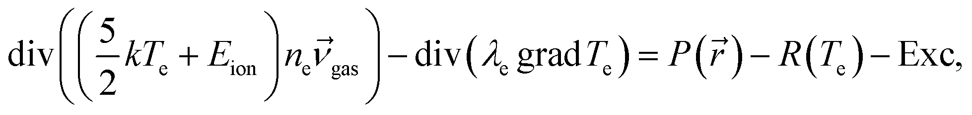 | (1) |
where me and ma are the masses of electron and Ar atom, respectively,
![[small nu, Greek, macron]](https://www.rsc.org/images/entities/i_char_e0ce.gif) collisions is the mean frequency of collisions of electrons and heavy particles. ne is calculated in the model using the Saha equation as function of Te:
collisions is the mean frequency of collisions of electrons and heavy particles. ne is calculated in the model using the Saha equation as function of Te: | (2) |
 is the thermal de Broglie wavelength of an electron, u0 and u1 are partition functions of the Ar atoms and ions, respectively. The energy exchange term Exc is introduced to the heat transfer equation of the plasma gas as a heat source.
The flow-chart for the implementation of this model is presented in Fig. 3b. Here PIM consists of the eqn (1) and (2) because they describe electron number density and electron temperature. These equations are solved inside the torch (see Fig. 1b). The following boundary condition is applied for eqn (1): Te = T. The description of calculation of parameters for the eqn (1) and (2) are given in Appendix B. In eqn (1)λe and P() depend on ne, which in turn depends strongly on Te. R and collisions depend on Te explicitly. This makes the eqn (1) not linear. Therefore, a non-linear system of eqn (1) and (2) and Maxwell eqn (3) should be solved together. For this the PIM and EMM are executed in a separate cycle until convergence (see Fig. 3b). Exc and (), which are results of the combined solution of eqn (1)–(3), are introduced in the FKM: PFKM() = Exc, FKM() = ().
2.3 Temperature of torch walls
The wall temperature is simulated in both models comprehensively in the FKM. It was found experimentally,1,35 that Twall can reach values of up to 800–900 K for the Fassel-type ICP torch and up to 1400 K for the SHIP torch, respectively, which is not far from the softening temperature of quartz. The latter is not surprising because there is no internal cooling flow of Ar in the SHIP torch, and the heat from the plasma is dissipated outside through the walls. To describe Twall more accurately, the loss of energy by radiation of the heated quartz should be taken into account. Therefore, a negative boundary heat source is introduced at the surface of the walls, which is equal to the surface power density of blackbody radiation sTwall4, where s is the Stefan–Boltzmann constant. No emissivity-caused corrections of the blackbody radiation law are made assuming that the emissivity of quartz is near 1. This assumption is in agreement with results of plasma diagnostics,1 where an emissivity of 0.97 was successfully applied for measurements of the wall temperature by an infrared camera (wavelength range 10–11 μm was used there).In Fig. 4, the calculated Twall on the outer surface of the wall (with and without taking wall radiation into account) is compared with experimental values of Twall measured earlier1 for the SHIP torch. Based on this comparison it was observed that the torch wall temperature is described much more accurate if the wall radiation is taken into account. Therefore, the wall radiation was introduced in the FKM for both LTE and two-temperature models and used for the investigation of both Fassel-type and SHIP torches below.
 | ||
| Fig. 4 Calculated and measured1 axial distribution of Twall on the outer surface of the SHIP torch as function of the coordinate z above the load coil (ALC), plasma is at optimal conditions. Breaks in the measured temperature are caused by the load coil turns, which are situated between the plasma torch and an IR camera, which was used for the measurements. | ||
2.4 Effect of tangential gas flow
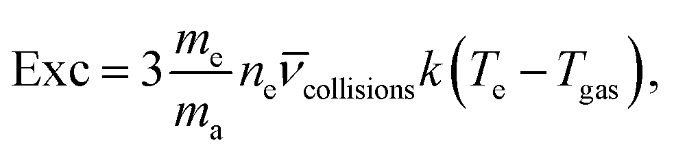
In most commercially available Fassel-type torches, a tangential gas flow is passed between the confining outer quartz tube and the sample introduction capillary. In the past, this tangential component of the gas velocity was included in some of the previously published models.2–5 However, this tangential component was not taken into account in some other simulations.7,8,27–30 To clarify this aspect, a tangential component of velocity νt is introduced in the FKM as boundary condition for input of the cooling and auxiliary gas flows. νt is estimated from the experimental setup: νt = factor × f/s, where f is the value of the cooling or auxiliary gas flow (in standard volume per second units), s is the area of the input channel of the cooling or auxiliary gas flow, respectively. The effect of the tangential gas flow was investigated by varying the factor empirically. In Fig. 5, the dependence of the calculated Icoil as function of this factor is presented. The introduction of the tangential flow in the LTE model results in a decrease of the resulting Icoil by more than 1.5 times. In the two-temperature model, the current is also influenced by the tangential flow, but to a smaller extent. Note also that the two-temperature model describes the electrical current better than the LTE model under these conditions. Therefore, the tangential flow is introduced in our models for the Fassel-type torch (the SHIP torch has no tangential flow in the experiments). | ||
| Fig. 5 Calculated and measured Icoil as function of a flow factor, which is proportional to tangential component of the introduced gas flows. Standard torch, optimal plasma conditions. | ||
3 Results and discussion
To validate the created models, we compare the results of our simulation with results of ICP models, which were published earlier. For this, geometry and parameters of the earlier published models were reproduced in our models. The LTE model is compared with the results of a simulation,12 where the values of Icoil and W are published, which deviate not more than 8% from our results. Also, the Ar/He mixture was introduced in the model, and our results are compared with results of a similar simulation.7 The two-temperature model is compared with results of another two-temperature model.10 In all cases, a good agreement of the results of our and previously published models is found (by visual inspection of the published data, no raw data was available from the cited simulation papers).In Fig. 6 distributions of power density, temperature, and gas velocity together with stream lines in the standard ICP torch, which were calculated using the LTE and the two-temperature models, are presented at optimal plasma conditions. In agreement with the earlier model,10 the two-temperature model predicts lower Te and Tgas than Tgas in the LTE model. In the area between the sample introduction capillary and the intermediate tube (in this area the auxiliary Ar flow is introduced into the plasma) a reverse flow of the gas (a vortex) is observed, which was also reported in very early ICP simulations2–6,9,10 and discussed later in connection with reverse flow of gas and nanoparticles in the ICP.8,29 In Fig. 6b and e, PFKM() is compared for the LTE and the two-temperature models. The LTE model predicts a higher maximum value of PFKM(). However, in the two-temperature model the power density is distributed in a larger volume, providing in this way a similar total power. This is explained by the fact that in the two-temperature model the electro-magnetic energy, which is consumed by plasma, is transferred to the gas through electrons. From the thermo-conductivity equation, the energy of electrons diffuses in the area to a certain degree. Therefore, the distribution of PFKM() in the two-temperature model is wider than in the LTE one.
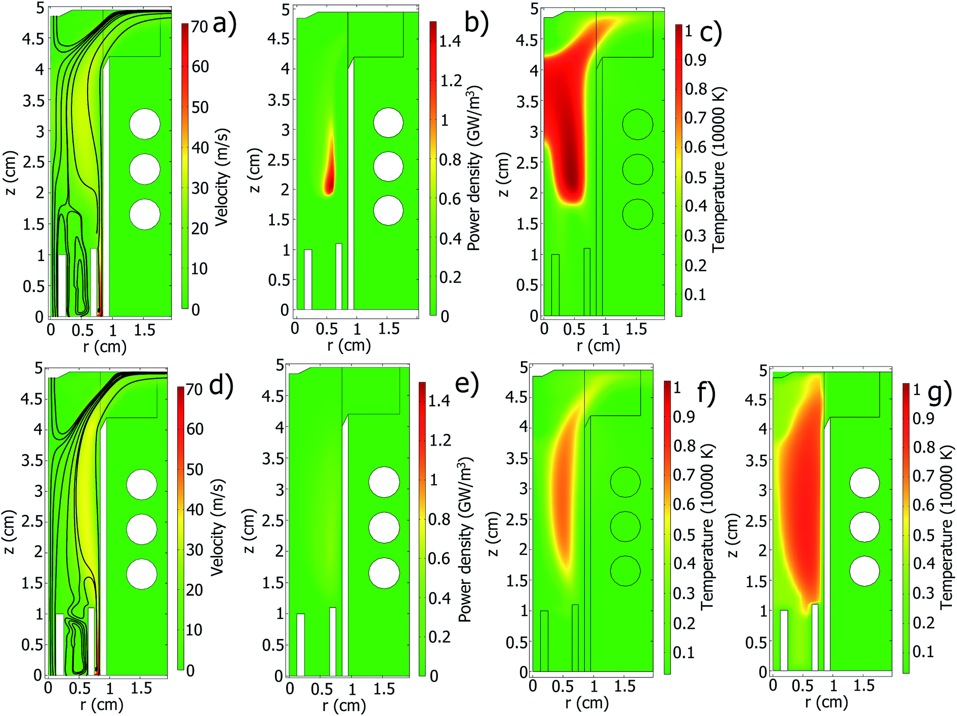 | ||
| Fig. 6 Results of simulation in the standard ICP torch with the LTE model (a–c) and with the two-temperature model (d–g): distribution of absolute gas velocity together with stream lines (a and d), density of power introduced into the Ar PFKM() (b and e), temperature of gas and walls T() (c and f), electron temperature Te() (g). Optimal plasma conditions. | ||
In Fig. 7, distributions of power density, temperature, and gas velocity together with streamlines in the SHIP torch at optimal plasma conditions are presented. Similarly to the standard torch, Te and Tgas in the two-temperature model are lower than Tgas in the LTE model. Again, the LTE model predicts a higher maximal value of PFKM(), but in the two-temperature model the power density is distributed in a larger volume (although the area occupied by PFKM() in the LTE and two-temperature model looks similar in Fig. 7b and e, maximum of PFKM() in the two-temperature model is situated closer to the confinement wall. Therefore, the distribution of the PFKM() spreads over a larger volume in the two-dimensional model owing to cylindrical configuration). The velocity of the cooling air is extremely high and exceeds even the speed of sound.
 | ||
| Fig. 7 Results of simulation in the SHIP torch with the LTE model (a–c) and with the two-temperature model (d–g): distribution of absolute gas velocity together with stream lines (a and d), density of power introduced into the Ar PFKM() (b and e), temperature of gas and walls T() (c and f), electron temperature Te() (g). In figures (a) and (d) internal and external areas of the torch are depicted with different velocity scale because the velocity of the cooling air outside is much higher than velocity of Ar inside the torch. Therefore the left color legend on these pictures corresponds to the internal area, and the right legend corresponds to the external area. Optimal plasma conditions. | ||
In Fig. 8, axial distributions of the wall temperature received from the models are compared with the temperatures measured in our complementary article.1 Both the LTE and the two-temperature models show a good agreement of Twall with corresponding experimental data for the SHIP torch. However, the models predict 1.8–2.6 times higher Twall in the standard torch.
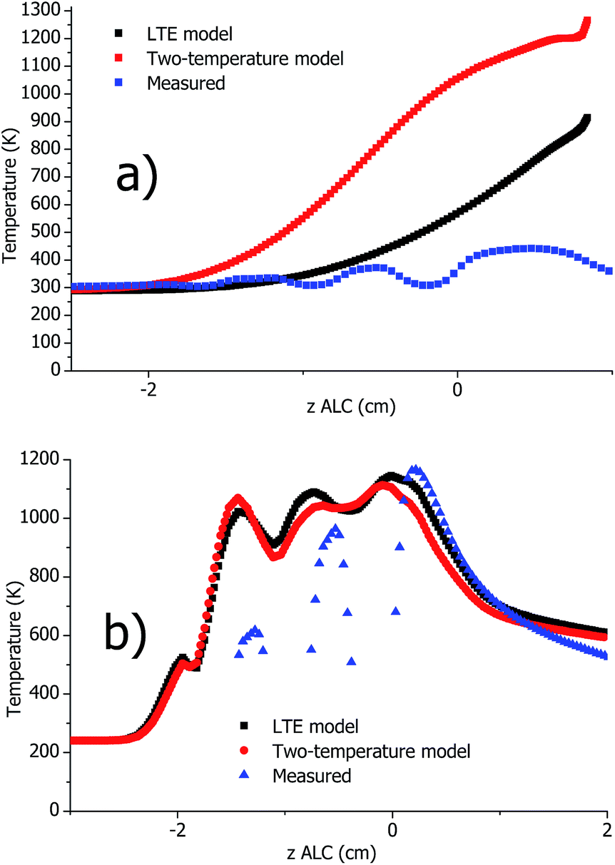 | ||
| Fig. 8 Calculated and measured1 axial distribution of Twall on the outer surface of the standard (a) and SHIP (b) torches (plasma operation at optimal conditions). Breaks in the measured temperatures are caused by the load coil turns, which are situated between the plasma torch and an IR camera, which was used for the measurements. | ||
Further, results of the simulations are compared with results of measurements over a wide range of operational plasma conditions.1,31 A summary of the used conditions is given in Table 2. Note that if any plasma parameter is changed, the power consumed by the plasma can also change.31 Therefore, the measured plasma power is also presented in the table and used as input parameter for the simulations.
| Parameter | Measured power (W) |
|---|---|
| Standard torch | |
| Nebulizer flow 0 L min−1 | 700 |
| Indicated power 1100 W | 950 |
| Without sample | 950 |
| Cooling flow 20 L min−1 | 1100 |
| Optimal conditions | 1150 |
| Counterflow through OPI 0.8 L min−1 | 1150 |
| Counterflow through OPI 0 L min−1 | 1200 |
| Nebulizer flow 1.5 L min−1 | 1200 |
| Cooling flow 11 L min−1 | 1250 |
| Auxiliary flow 2 L min−1 | 1350 |
| Indicated power 1400 W | 1450 |
| Auxiliary flow 0.6 L min−1 | 1500 |
|
|
| SHIP torch | |
| Indicated power 1000 W | 500 |
| Nebulizer flow 0 L min−1 | 550 |
| Auxiliary flow 0.4 L min−1 | 600 |
| Auxiliary flow 0.6 L min−1 | 600 |
| Without sample | 600 |
| Optimal conditions | 750 |
| Air cooling flow 150 L min−1, input air pressure 3 bar | 750 |
| Air cooling flow 340 L min−1, input air pressure 7 bar | 750 |
| Indicated power 1200 W | 800 |
| Nebulizer flow 0.6 L min−1 | 800 |
It is assumed in the literature that the ICP has a toroidal structure determined by the skin effect, which limits penetration of electro-magnetic fields from the load coil into the plasma (see for example ref. 5, 6 and 12). In an early work of Fassel36 it was found that nebulizer gas flow has an influence of toroidal structure of the plasma. We have also measured1 that the plasma in both the standard and the SHIP torches has a toroidal structure at optimal conditions and has no toroidal structure anymore, if there is no nebulizer gas flow. To simulate this effect, the plasma without nebulizer flow is modeled; the results are presented in Fig. 9. Similarly to the optimal plasma conditions, the density of power transferred into the plasma gas without the nebulizer gas flow has a toroidal structure (although the power density without the nebulizer flow is not presented here to avoid overloading of figures, it looks very similar to Fig. 6b and e and 7b and e respectively). However the LTE model for the standard torch and both models for the SHIP torch result in no toroidal structure of the gas temperature. This can be explained by features of the heat transfer in the ICP: the heat energy, which is introduced into the plasma toroidally according to the density of the electro-magnetic power, is then transferred to the nearby areas conductively or convectively. In the outer areas, the heat energy is removed by the cooling gas flow or through the torch walls. If there is no nebulizer flow, in the inner areas the heat is not removed from the plasma effectively, and the gas temperature comes to balance with the temperature of the surrounding hot gas. Thus, there is an important role of the nebulizer gas flow for the formation of the toroidal structure of the plasma temperature. The two-temperature model of the standard torch does not eliminate the toroidal structure, but the structure becomes less visible in this case.
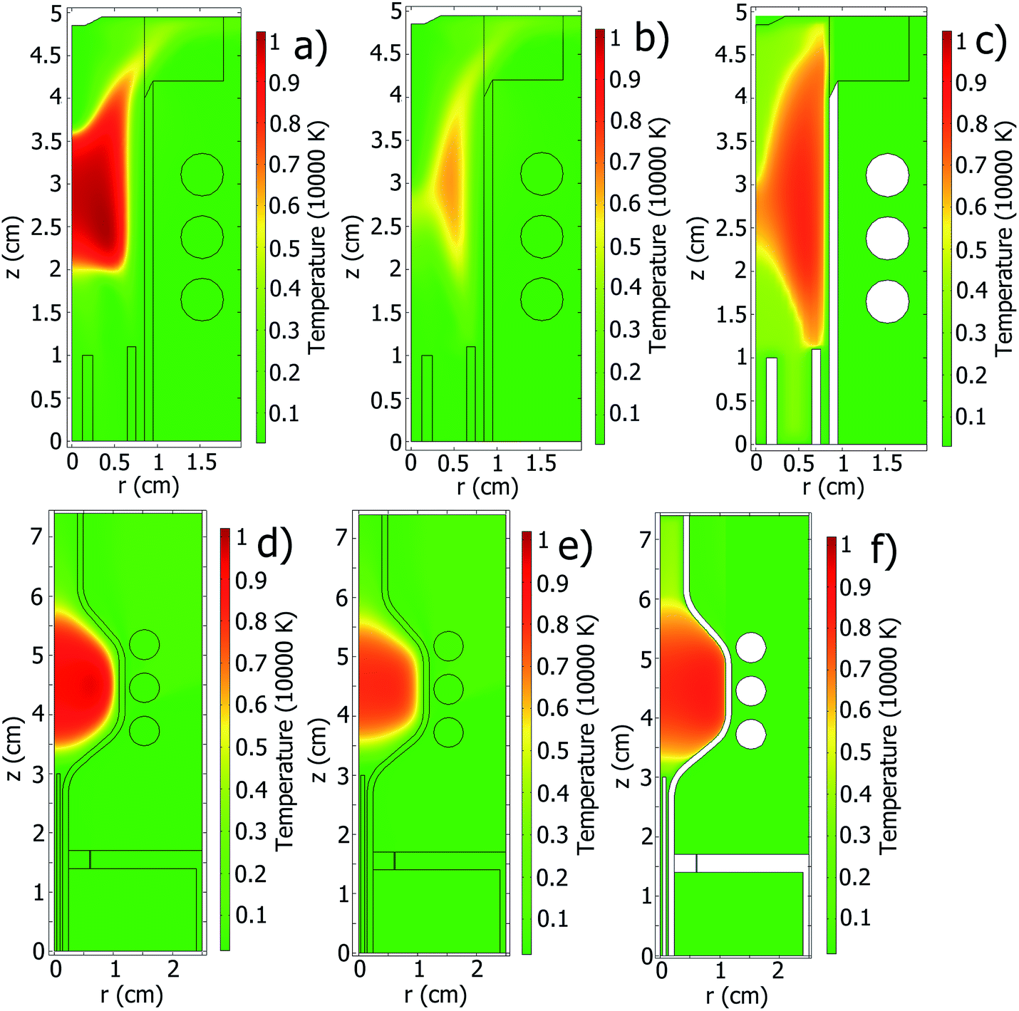 | ||
| Fig. 9 Results of simulation in the standard ICP (a–c) and SHIP (d–f) torches without nebulizer flow: temperature of gas and walls T() from the LTE model (a and d), T() (b and e) and electron temperature Te() (c and f) from the two-temperature model. | ||
In Fig. 10–12, results of the ICP simulations in both sources over a wide range of different parameters are compared with experimentally determined ICP properties.1,31 This comparison should be carried out cautiously because the developed models do not support sample introduction yet, while most of the plasma diagnostic results were obtained with sample introduction. For illustrative purposes, the calculated and measured results are plotted as a function of ICP power, which was measured and introduced into the models as an input parameter. A list of all used parameters is presented in Table 2.
In Fig. 10, Icoil measured and calculated for different conditions is presented. Both models predict the electrical currents satisfactory, but there are minor differences. For the standard torch, the two-temperature model has twice less deviations from the experimentally measured Icoil than the LTE model. However, for the SHIP torch the situation is opposite: for most plasma conditions the LTE model has twice less deviations than the two-temperature model. In both cases Icoil follows W. Different factors can explain difference of the calculated and the measured electrical current: accuracy of the models, degree of LTE in the plasma, absence of the sample in the models. Most deviations in Fig. 10 don't exceed 25%, which is a good result for simulations.
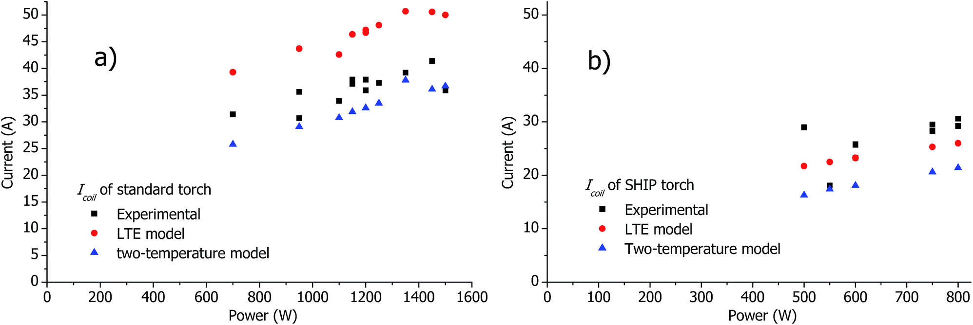 | ||
| Fig. 10 Calculated and measured current in the coil Icoil in the standard torch (a) and in the SHIP torch (b) in a wide range of operational conditions (see Table 2). | ||
In Fig. 11, the measured rotational temperature Trot, excitation temperature Texc and electron temperature Te are compared with the calculated values of Tgas and Te. Maximal values of distributions of the calculated Tgas() and Te() are used in Fig. 11. The maximum is situated at z = 2–3 cm (see Fig. 6 and 7). Thus for the correct comparison the measured Trot, Texc and Te published in our complementary article1 were averaged over space between the 1st and the 2nd turn of the load coil (see Fig. 1b) and presented in Fig. 11. For both torches, the measured Trot and Texc are similar for almost all plasma conditions. The measured Te is significantly higher than Trot and Texc. Tgas calculated by the LTE model is similar to the measured Te.
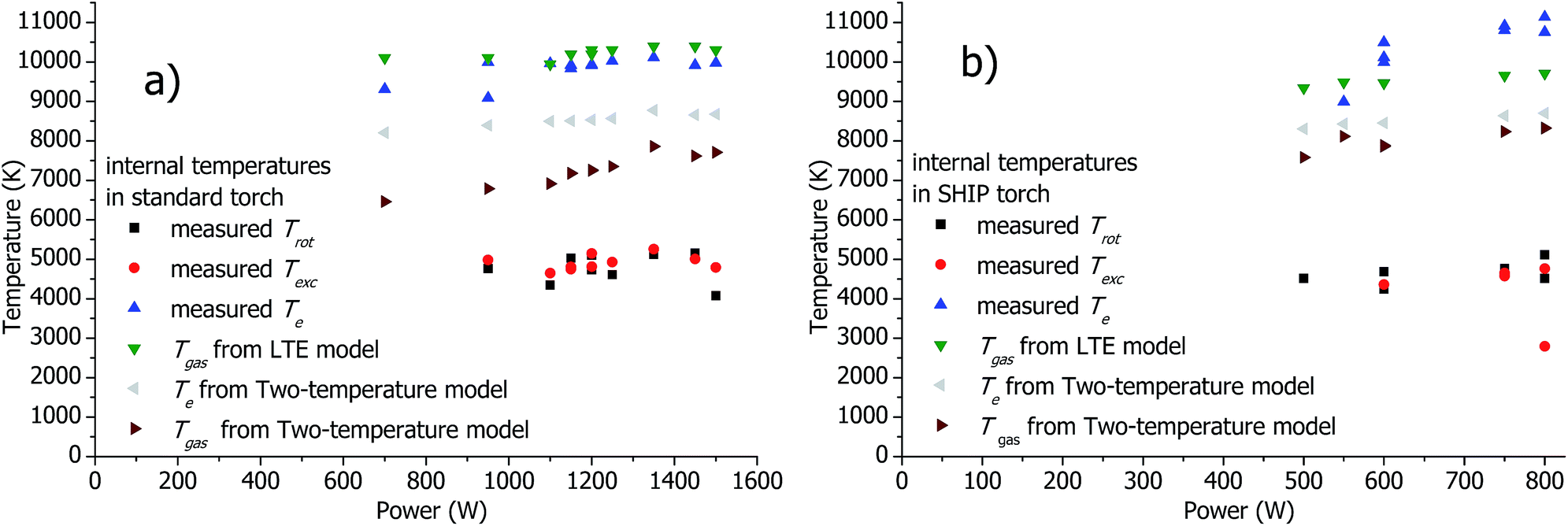 | ||
| Fig. 11 Calculated and measured plasma temperatures in the standard torch (a) and in the SHIP torch (b) in a wide range of operational conditions (see Table 2). | ||
The following relations between the temperatures are seen from Fig. 11: Te ≈ TLTEgas > Te2T > Tgas2T > Trot ≈ Texc, where the upper index LTE denoted results obtained from the LTE model, the upper index 2T denoted results obtained from the two-temperature model.
Fig. 12 depicts Twall (maximal value across the calculated or measured axial distribution of the wall temperature) calculated and measured in a wide range of parameters. For the SHIP torch, both the LTE and the two-temperature model show good agreement with the experimentally measured wall temperature. However, for the standard torch the models predict significantly higher Twall.
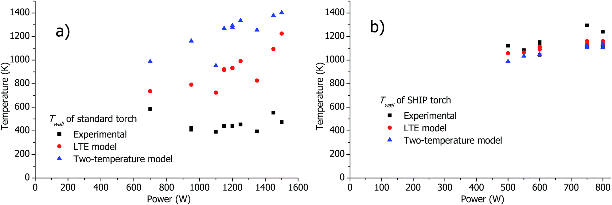 | ||
| Fig. 12 Calculated and measured Twall (maximal calculated or measured wall temperature along the axis) in the standard torch (a) and in the SHIP torch (b) in a wide range of operational conditions (see Table 2). | ||
Despite the fact that sample introduction is not incorporated into our ICP models yet, the potential influence of sample loading and droplets on the plasma properties can be somewhat deduced from a comparison of the calculated and the measured data. In Table 3, measured and calculated Icoil for the standard and the SHIP torch are presented. It is observed that at equal plasma power the introduction of the sample increases the electrical current in the load coil. This is very interesting but not surprising, because the sample cools down the plasma and hence reduces the degree of ionization and electrical conductivity. Thus more electrical current is needed to keep the energy consumed by the plasma at the same level.
| Power (W) | Current (A) | ||
|---|---|---|---|
| Calculated | Measured | ||
| Standard torch with sample | 950 | 37.1 | |
| Standard torch without sample | 950 | 29.1 (two-temperature model) | 30.7 |
| SHIP torch with sample | 750 | 30.2 | |
| SHIP torch without sample | 750 | 23.2 (LTE model) | 23.3 |
4 Conclusions
An LTE-based model and a two-temperature model of the ICP are developed and applied to two completely different torch geometries: a standard Fassel-type torch and a low-argon-flow torch (SHIP), the latter of which consumes only 0.6 L min−1 of Ar. The models themselves are validated with previously published LTE and two-temperature models and found to be in good agreement. Most importantly, the results of the models are directly compared with electrical characteristics and internal plasma properties (rotation, excitation and electron temperatures) in these torches in a wide range of plasma conditions, which were measured experimentally in recently published studies. Therefore, the model can be applied for a straightforward optimization of different ICP torches.The LTE model describes gas-dynamical properties satisfactory. For example, it describes the reverse gas flow and the formation of the toroidal plasma structure after the introduction of the nebulizer gas flow into the model. In a wide range of parameters, the gas temperature predicted by this model is a good approximation of the experimentally measured electron temperature. Drawbacks of the LTE model are, first, that the plasma seems to be not in the local thermodynamic equilibrium, as it is indicated by the difference of experimentally measured plasma temperatures, and, second, that the LTE model gives significant deviations of calculated and measured electrical plasma properties in the standard ICP torch.
The two-temperature model also describes the gas dynamic properties satisfactory. In contrast to the LTE model, the two-temperature model results in a better agreement between the calculated and measured electrical properties for the standard ICP torch when compared to the values for the SHIP torch. The following relation is found for the measured and calculated temperatures in the plasma: Te ≈ TLTEgas > Te2T > Tgas2T > Trot ≈ Texc, where the upper index LTE denoted results obtained from the LTE model, the upper index 2T denoted results obtained from the two-temperature model. This points out to a possible reason for deviations between the results of the two-temperature model and experimentally measured plasma properties: most of the experimental data are measured with sample introduction into the plasma, which can enhance deviations from LTE.
The simulation of the torch wall temperature is included in the presented models. Both models describe the wall temperature well for the SHIP torch, as indicated by a good agreement with the measured wall temperature. However, significant deviations of the calculated and measured wall temperatures for the standard torch were found. It is assumed that convective cooling of the walls a likely reason. Convective cooling is not well simulated yet and will be part of a future study.
Appendix A. Implementation of the EMM
The electro-magnetic fields are calculated using vector potential formulation with assumption of harmonic RF-oscillations of the electro-magnetic fields. Only the tangential component of the vector potential is taken into account due to cylindrical symmetry:5,6,12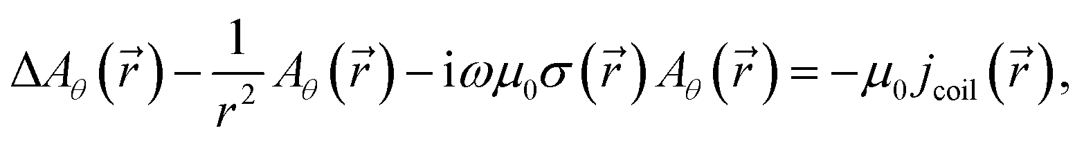 | (3) |
where
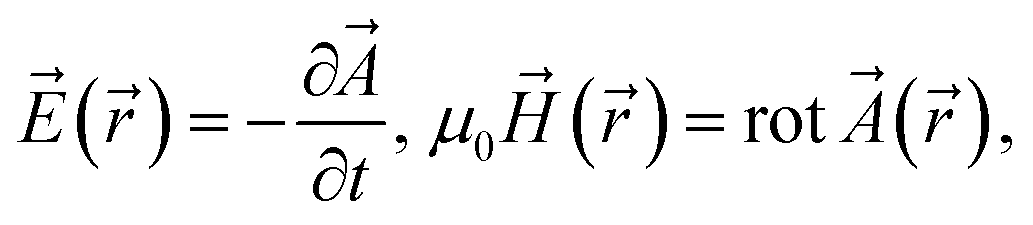
![[A with combining right harpoon above (vector)]](https://www.rsc.org/images/entities/i_char_0041_20d1.gif) is the complex amplitude of the vector potential, Aθ the tangential component of , ω the angular RF-frequency, μ0 the permeability of the free space, jcoil the amplitude of density of the electrical current flowing in the coil,
is the complex amplitude of the vector potential, Aθ the tangential component of , ω the angular RF-frequency, μ0 the permeability of the free space, jcoil the amplitude of density of the electrical current flowing in the coil, ![[E with combining right harpoon above (vector)]](https://www.rsc.org/images/entities/i_char_0045_20d1.gif) and
and ![[H with combining right harpoon above (vector)]](https://www.rsc.org/images/entities/i_char_0048_20d1.gif) are the complex amplitudes of electric and magnetic fields, respectively. It is assumed that the coil current is distributed homogeneously inside the coil. If the coil current Icoil is specified as the input parameter, then jcoil = Icoil/s, where s is the area of cross-section of the load coil. Otherwise Icoil = 1 A is used. In this case, Aθ and Icoil are easily corrected later to match the specified plasma power.
are the complex amplitudes of electric and magnetic fields, respectively. It is assumed that the coil current is distributed homogeneously inside the coil. If the coil current Icoil is specified as the input parameter, then jcoil = Icoil/s, where s is the area of cross-section of the load coil. Otherwise Icoil = 1 A is used. In this case, Aθ and Icoil are easily corrected later to match the specified plasma power.
It is assumed in the model that 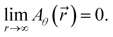 Therefore, Aθ behaves asymptotically similarly to the field of the magnetic dipole far from plasma and load coil. To implement this boundary condition, the boundary for the eqn (3) is formed as a cylinder, which is collinear to the torch axis. The plasma torch is situated in the center of the boundary cylinder. At the border of the boundary cylinder, the asymptotic behavior of the magnetic dipole is used as the boundary condition13 for
 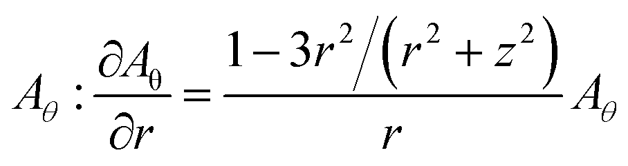 at the cylindrical surface, and
 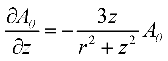 at plane sides of the cylinder. The size of the boundary cylinder is found empirically to eliminate the influence of the cylinder's size on the solution inside the torch.
As Aθ is calculated, the power density P() and Lorentz force () are calculated:5,6,12,13P() = 1/2σ()|()|2, () = 1/2μ0σ()Re(() × ()). If the plasma power is specified as the input parameter, then Aθ is additionally corrected to provide the specified plasma power: Anewθ() = factor × Aθ(), where 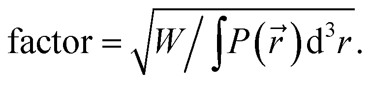 Correspondingly, Icoil, P() and () are also corrected: Inewcoil = factor × Icoil, Pnew() = factor2 × P(), new() = factor2 × ().
Appendix B. Calculation of parameters of the models
The thermal conductivity, thermal capacity, and viscosity of the ionized gas are calculated as described in the work of Lindner et al.,7 where a gas-kinetic model is used with the assumption that the composition of the gas can include some elements; for each element several degrees of ionization can be taken into account. In our models, Ar neutrals, singly and doubly ionized atoms are used.Based on the similar gas-kinetic approach, the following parameters of the models are calculated:
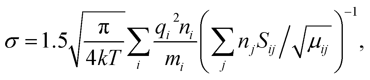
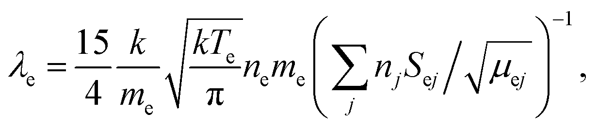
where λe is the thermal conductivity of electrons for two-temperature model.
 collisions as function of Tgas and Te is adopted from ref. 10. u0 and u1 from the eqn (2) are taken from ref. 37. The density of radiation losses of Ar R as function of Te (as function of Tgas in the LTE model) is taken from ref. 32.
Acknowledgements
The authors would like to thank Helmut Lindner for consultations about his ICP model. Financial support from the German Research Foundation, grant No. BU 1140/5-1, HO 2062/9-1, is gratefully acknowledged.References
- M. Voronov, V. Hoffmann, C. Engelhard and W. Buscher, J. Anal. At. Spectrom., 2017 10.1039/c6ja00191b.
- M. I. Boulos, R. Gagne and R. M. Barnes, Can. J. Chem. Eng., 1980, 58, 367–381 CrossRef CAS.
- J. Mostaghimi, P. Proulx and M. I. Boulos, Plasma Chem. Plasma Process., 1984, 4(3), 199–217 CrossRef CAS.
- J. Mostaghimi, P. Proulx and M. I. Boulos, Numer. Heat Transfer, 1985, 8, 187–201 Search PubMed.
- J. Mostaghimi and M. I. Boulos, Plasma Chem. Plasma Process., 1989, 9(1), 25–44 CrossRef.
- P. Yang, R. M. Barnes, J. M. Mostaghimi and M. I. Boulos, Spectrochim. Acta, Part B, 1989, 44, 657–666 CrossRef.
- H. Lindner and A. Bogaerts, Spectrochim. Acta, Part B, 2011, 66, 421–431 CrossRef CAS.
- M. Aghaei and A. Bogaerts, J. Anal. At. Spectrom., 2016, 31, 631–641 RSC.
- J. Mostaghimi, P. Proulx and M. Boulos, J. Appl. Phys., 1987, 61, 1753–1760 CrossRef CAS.
- J. Mostaghimi and M. Boulos, J. Appl. Phys., 1990, 68, 2643–2648 CrossRef.
- S. H. Paik and E. Pfender, Plasma Chem. Plasma Process., 1990, 10, 167–188 CrossRef CAS.
- S. Xue, P. Proulx and M. I. Boulos, J. Phys. D: Appl. Phys., 2001, 34, 1897–1906 CrossRef CAS.
- D. Bernardi, V. Colombo, E. Ghedini and A. Mentrelli, Eur. Phys. J. D, 2003, 27, 55–72 CrossRef CAS.
- J. Horner and G. M. Hieftje, Spectrochim. Acta, Part B, 1998, 53, 1235–1259 CrossRef.
- C. M. Benson, S. F. Gimelshein, D. A. Levin and A. Montaser, Spectrochim. Acta, Part B, 2001, 56, 1097–1112 CrossRef.
- C. M. Benson, S. F. Gimelshein, D. A. Levin and A. Montaser, Rarefied Gas Dynamics: 22nd International Symposium, AIP Conf. Proc., 2001, 585, 246–253 CrossRef CAS.
- J. A. Horner, S. A. Lehn and G. M. Hieftje, Spectrochim. Acta, Part B, 2002, 57, 1025–1042 CrossRef.
- C. M. Benson, J. Zhong, S. F. Gimelshein, D. A. Levin and A. Montaser, Spectrochim. Acta, Part B, 2003, 58, 1453–1471 CrossRef.
- Y. Shan and J. Mostaghimi, Spectrochim. Acta, Part B, 2003, 58, 1959–1977 CrossRef.
- Y. Shan and J. Mostaghimi, Plasma Chem. Plasma Process., 2005, 25(3), 193–214 CrossRef CAS.
- M. Cai, A. Montaser and J. Mostaghimi, Spectrochim. Acta, Part B, 1993, 48, 789–807 CrossRef.
- M. Cai, A. Montaser and J. Mostaghimi, Appl. Spectrosc., 1995, 49, 1390–1402 CrossRef CAS.
- M. El-Hage, J. Mostaghimi and M. I. Boulos, J. Appl. Phys., 1989, 65(11), 4178–4185 CrossRef.
- K. Y. Nagulin, D. S. Akhmetshin, A. K. Gilmutdinov and R. A. Ibragimov, J. Anal. At. Spectrom., 2015, 30, 360 RSC.
- M. V. Morozov, A. E. Staroverov, A. K. Gilmutdinov and M. K. Salakhov, Uchenye Zapiski Kazanskogo Universiteta. Seriya Fiziko-Matematicheskie Nauki, 2008, 153(1), 62–72 Search PubMed.
- V. Colombo, E. Ghedini and J. Mostaghimi, IEEE Trans. Plasma Sci., 2008, 36(4), 1040–1041 CrossRef CAS.
- M. Aghaei, H. Lindner and A. Bogaerts, Spectrochim. Acta, Part B, 2012, 76, 56–64 CrossRef CAS.
- M. Aghaei, H. Lindner and A. Bogaerts, J. Anal. At. Spectrom., 2012, 27, 604–610 RSC.
- M. Aghaei, L. Flamigni, H. Lindner, D. Günther and A. Bogaerts, J. Anal. At. Spectrom., 2014, 29, 249–261 RSC.
- M. Aghaei, H. Lindner and A. Bogaerts, J. Anal. At. Spectrom., 2013, 28, 1485–1492 RSC.
- M. Voronov, V. Hoffmann, D. Birus, C. Engelhard and W. Buscher, J. Anal. At. Spectrom., 2015, 30, 2089–2098 RSC.
- A. T. M. Wilbers, J. J. Beulens and D. C. Schram, J. Quant. Spectrosc. Radiat. Transfer, 1991, 46, 385–392 CrossRef CAS.
- M. R. Zaghloul, M. A. Bourham and J. M. Doster, J. Phys. D: Appl. Phys., 2000, 33, 977–984 CrossRef CAS.
- M. R. Zaghloul, Phys. Rev. E: Stat., Nonlinear, Soft Matter Phys., 2004, 69, 026702 CrossRef PubMed.
- C. Engelhard, A. Scheffer, T. Maue, G. M. Hieftje and W. Buscher, Spectrochim. Acta, Part B, 2007, 62, 1161–1168 CrossRef.
- G. W. Dickinson and V. A. Fassel, Anal. Chem., 1969, 41, 1021–1024 CrossRef CAS.
- A. W. Irwin, Astrophys. J., Suppl. Ser., 1981, 45, 621–633 CrossRef CAS.
- C. Engelhard, A. Scheffer, S. Nowak, T. Vielhaber and W. Buscher, Anal. Chim. Acta, 2007, 583, 319–325 CrossRef CAS PubMed.
Footnote |
| † Electronic supplementary information (ESI) available. See DOI: 10.1039/c6ja00192k |
| This journal is © The Royal Society of Chemistry 2017 |