
 Open Access Article
 This Open Access Article is licensed under a Creative Commons Attribution-Non Commercial 3.0 Unported Licence
Solar thermochemical splitting of CO2 into separate streams of CO and O2 with high selectivity, stability, conversion, and efficiency†
Daniel
Marxer
,
Philipp
Furler
,
Michael
Takacs
and
Aldo
Steinfeld
 *
*
Department of Mechanical and Process Engineering, ETH Zurich, 8092 Zurich, Switzerland. E-mail: aldo.steinfeld@ethz.ch
First published on 21st February 2017
Abstract
Developing solar technologies for converting CO2 into fuels has become a great energy challenge, as it closes the anthropogenic carbon cycle and leads to the production of sustainable transportation fuels on a global scale. However, the low mass conversion, poor selectivity, and/or low energy efficiency of current approaches have hindered their industrial implementation. Here, we experimentally demonstrate the solar-driven thermochemical splitting of CO2 into separate streams of CO and O2 with 100% selectivity, 83% molar conversion, and 5.25% solar-to-fuel energy efficiency. This benchmark performance was accomplished using a 4 kW solar reactor featuring a reticulated porous structure, made of ceria, directly exposed to 3000× flux irradiation and undergoing redox cycling via temperature/pressure-swing operation. The dual-scale interconnected porosity (mm and μm-sized pores) of the ceria structure provided volumetric radiative absorption and enhanced heat/mass transport for rapid redox kinetics, while 500 consecutive redox cycles further validated material stability and structure robustness. A detailed energy balance elucidates viable paths for achieving higher efficiencies and for large-scale industrial implementation using an array of modular solar reactors integrated into the established solar concentrating infrastructure.
Broader contextSustainable utilization of liquid hydrocarbon fuels for transportation, especially for the aviation sector, can be realized with the help of solar technologies that convert CO2 into fuels. Thermochemical approaches for splitting CO2 using concentrated solar radiation inherently operate at high temperatures and utilize the entire solar spectrum, and as such provide a favorable thermodynamic path to solar fuel production with potentially high efficiency. We report on the experimental demonstration of the solar-driven thermochemical splitting of CO2 into separate streams of CO and O2 using a reduction–oxidation (redox) cyclic process with total selectivity, long-term stability, high mass conversion, and a solar-to-fuel energy efficiency comparable to the highest value reported to date. Crucial to this accomplishment was a robust solar reactor containing a ceria structure that absorbed radiation volumetrically and exhibited rapid reaction kinetics. The experimental results obtained under realistic high-flux operational conditions provide compelling evidence of the viability of the solar thermochemical redox technology for converting CO2 to fuels on a large scale. We elucidate the efforts required for the large-scale industrial implementation of this technology, which notably can make use of the solar concentrating infrastructure already established for commercial solar thermal power plants. |
1. Introduction
Sustainable utilization of liquid hydrocarbon fuels for transportation can be realized with the help of technologies that convert CO2 into fuels using solar energy.1,2 The key indicator of their economic feasibility is the solar-to-fuel energy efficiency ηsolar-to-fuel – defined as the ratio of the heating value of the fuel produced to the solar energy input – but current values obtained for the solar splitting of CO2 into CO and O2 are still in the single digits. The highest efficiencies reported for solar-driven electrochemical and photochemical processes are 6.5% using a PV-electrolyzer,3 2% using a PV-photoelectrochemical cell,4 and less than 1% for photochemical cells.5 These approaches use water as the electron source and co-produce H2, but neither the fuel purity nor its quality (e.g. H2![[thin space (1/6-em)]](https://www.rsc.org/images/entities/char_2009.gif) :CO ratio) can be well controlled, usually producing an impractical fuel highly diluted in unreacted CO2 as well as introducing costly downstream processing for adjusting the fuel composition. Of particular interest is the splitting of pure CO2 in the absence of water, as it closes the anthropogenic carbon cycle without constraints on water availability, provided that CO2 is captured from air or is derived from a biomass source. It further enables a better control of the CO2-to-CO conversion and, therefore, the fuel purity. If liquid hydrocarbon fuels are the final target, the separate splitting of CO2 and H2O for producing both CO and H2 is advantageous as it enables tight control of the syngas's purity and quality required for gas-to-liquid processing. This approach is supported by detailed techno-economic analyses6,7 that point to the energy irreversibilities and cost penalties associated with splitting only H2O, shifting a portion of H2 to CO via the endothermic reverse water–gas shift reaction (H2 + CO2 = H2O + CO, ΔH273K = 41 kJ mol−1 CO2) to obtain the desired H2:CO ratio, and separating unreacted CO2. In contrast, if the targeted fuel is CH4, the splitting of H2O followed by the exothermic Sabatier reaction (4H2 + CO2 = CH4 + 2H2O, ΔH273K = −164 kJ mol−1 CO2) may be the preferred path because of the higher ηsolar-to-fuel and fewer steps.
:CO ratio) can be well controlled, usually producing an impractical fuel highly diluted in unreacted CO2 as well as introducing costly downstream processing for adjusting the fuel composition. Of particular interest is the splitting of pure CO2 in the absence of water, as it closes the anthropogenic carbon cycle without constraints on water availability, provided that CO2 is captured from air or is derived from a biomass source. It further enables a better control of the CO2-to-CO conversion and, therefore, the fuel purity. If liquid hydrocarbon fuels are the final target, the separate splitting of CO2 and H2O for producing both CO and H2 is advantageous as it enables tight control of the syngas's purity and quality required for gas-to-liquid processing. This approach is supported by detailed techno-economic analyses6,7 that point to the energy irreversibilities and cost penalties associated with splitting only H2O, shifting a portion of H2 to CO via the endothermic reverse water–gas shift reaction (H2 + CO2 = H2O + CO, ΔH273K = 41 kJ mol−1 CO2) to obtain the desired H2:CO ratio, and separating unreacted CO2. In contrast, if the targeted fuel is CH4, the splitting of H2O followed by the exothermic Sabatier reaction (4H2 + CO2 = CH4 + 2H2O, ΔH273K = −164 kJ mol−1 CO2) may be the preferred path because of the higher ηsolar-to-fuel and fewer steps.
Solar thermochemical approaches for splitting CO2 using concentrated solar radiation inherently operate at high temperatures and utilize the entire solar spectrum, and as such provide a favorable thermodynamic path to solar fuel production with potentially high ηsolar-to-fuel. The thermodynamic limit is given by8
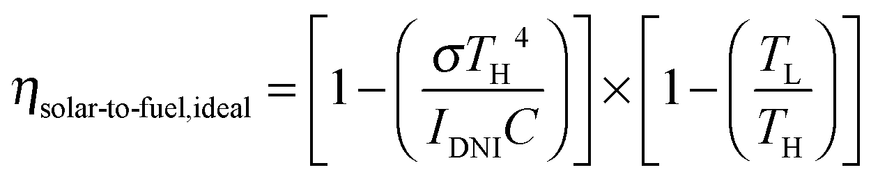 | (1) |
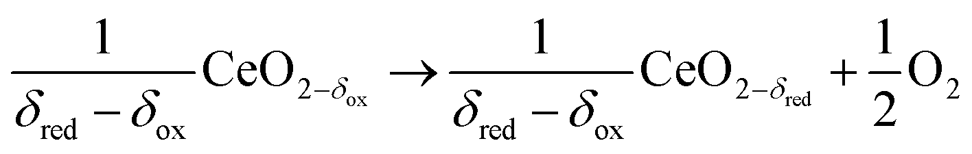
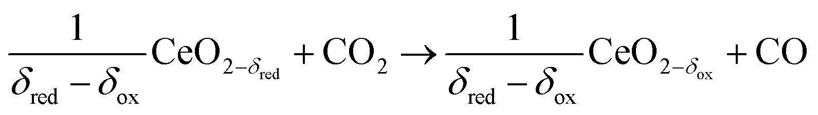
In contrast to the direct thermolysis of CO2, two-step thermochemical cycles using metal oxide redox reactions bypass the need for high-temperature CO/O2 separation.8,10 In the first endothermic step at Treduction, the metal oxide is endothermally reduced using concentrated solar process heat to generate O2. In the second exothermic step at Toxidation, the reduced metal oxide is re-oxidized with CO2 to generate CO. Such a redox cycle can also be applied for splitting H2O into separate streams of H2 and O2 by simply substituting CO2 for H2O in the oxidation step (eqn (3)). Among the candidate metal oxides, ceria has emerged as an attractive redox material because of its high oxygen ion diffusivity, crystallographic stability, and abundance in the earth's crust comparable to that of copper.11,12 The redox cycle is represented by the net reactions listed in Table 1, where δ denotes the nonstoichiometry – the measure of the reduction/oxidation extent. At equilibrium, δ is a function of temperature and oxygen partial pressure pO2.13 Thus, in principle, the redox cycle can be operated under either a temperature-swing mode and/or a pressure-swing mode to control the oxygen exchange capacity of ceria, given by Δδ = δred − δox, and thereby the fuel yield per cycle. Isobaric cycling, i.e. temperature-only-swing mode, suffers from heat losses and thermal stresses imposed by the temperature gradients,8,10 while isothermal cycling, i.e. pressure-only-swing mode, suffers from low fuel yields imposed by the thermodynamics.14–17 It is evident that a proper combination of both temperature-swing and pressure-swing modes can alleviate the aforementioned drawbacks and facilitate flexible operation for maximizing ηsolar-to-fuel. For example, application of a moderate pressure swing to reduce pO2 from 10 to 0.1 mbar and operate the reduction step at Treduction = 1500 °C and pO2 = 0.1 mbar (eqn (2)) and the oxidation step at Toxidation = 900 °C and pCO2 = 1 bar (eqn (3)) enables an increase of Δδ by a factor of 2.5 (from 0.016 to 0.040),13 or alternatively it enables the same Δδ value of 0.016 while lowering Treduction from 1500 to 1390 °C. Both situations lead to an increase of ηsolar-to-fuel because of the higher specific fuel output (the former case) or reduced heat losses (the latter case). The optimal combination of Δp and ΔT depends strongly on the energy required to perform the reduction at a low pO2 value. Previous experimental work employed a flow of inert gas to maintain a low pO2 and sweep up the O2 evolved during the reduction step17–20 but the energy penalty for separating and recycling the inert gas detrimentally affected ηsolar-to-fuel. Alternatively, pO2 can be effectively controlled by operating under vacuum pressures, which, as it will be shown in the analysis that follows, requires comparatively less energy, rapidly equilibrates pO2 within the reacting material, reduces considerably conductive and convective heat losses, and produces pure O2 as a byproduct.
|
Reduction at Treduction and pO2 (ptotal ≤ 1 bar)
ΔH ≈ 475 kJ per 1/2 mole of O2 |
|
|||
|
Oxidation at Toxidation and pCO2 (ptotal = 1 bar)
ΔH ≈ −192 kJ per mole of CO2 |
|
|||
|
Net
ΔH = 283 kJ per mole CO2 |
|
|||
Solar reactor concepts using packed beds,17 porous structures,18–20 rotating components,21–22 and moving particles23–25 have been proposed for effecting the ceria redox cycle. For all, efficient heat/mass transfer are desired characteristics that are, obviously, strongly dependent on the material morphology and reactor configuration. We have investigated various ceria porous structures enclosed by a solar cavity-receiver, including monolithic bricks18 and fibrous felts19 with μm-size pores, as well as reticulated porous ceramics (RPC) with mm-size pores.26 The best performance to date was obtained using a RPC structure featuring dual-scale porosity with interconnected pores in the mm and μm ranges.27 This is because the larger void size of the mm-sized pores enables efficient heat transfer by volumetric absorption of concentrated solar radiation during the endothermic reduction (eqn (2)), while the smaller void size of the μm-sized pores within the struts provides a high surface area for fast reaction rates during the exothermic oxidation with CO2 (eqn (3)). Using this dual-scale RPC structure we have recently demonstrated28 the entire production chain to solar kerosene from H2O and CO2. The syngas's quality was shown to be suitable for direct Fischer–Tropsch synthesis28 and methanol synthesis.29ηsolar-to-fuel reached 1.72%, partly because of the energy penalty associated with inert gas consumption as well as non-uniform temperature and fluid flow distribution.26,28,30 Here, we describe the design and operation of a solar reactor for performing the splitting of CO2 with an energy efficiency that has been boosted by a factor of 3 (or a factor of 13 higher than the value obtained for structures with only μm-size pores18), while simultaneously yielding total selectivity and high molar conversion. The stable experimental results obtained under realistic high-flux operational conditions provide compelling evidence of the viability of the solar thermochemical redox technology for converting CO2 to fuels on a large scale.
2. Solar reactor
Design
The solar reactor is shown schematically in Fig. 1. Its configuration has been optimized by applying 3D heat transfer and fluid dynamic computations.30 It consists of a 100 mm-inner diameter, a 75 mm-depth cylindrical cavity-receiver with a 4 cm-diameter circular aperture sealed by a 4 mm-thick clear fused quartz disk window for the access of concentrated solar radiation. The cavity contains an octagonal 25 mm-thick RPC structure made of pure ceria. With this arrangement, the RPC structure is directly exposed to the high-flux irradiation, enabling volumetric absorption and uniform heating.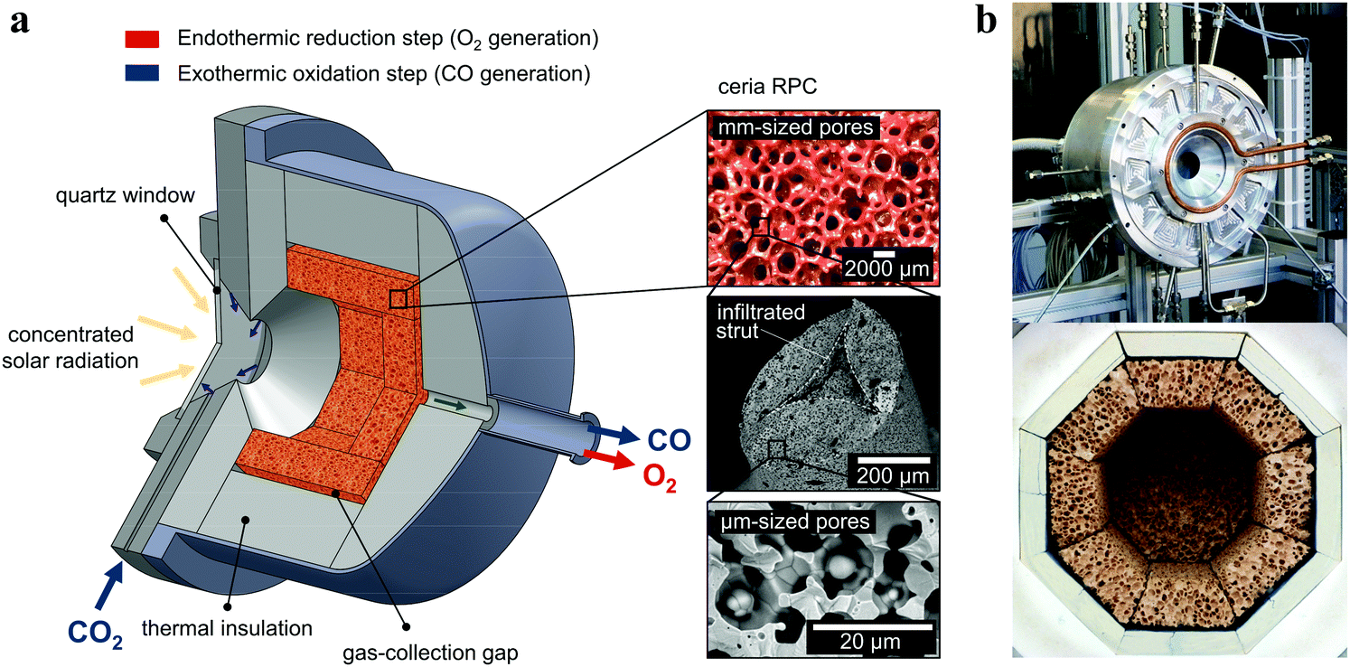 | ||
| Fig. 1 (a) Schematic of the solar reactor configuration for splitting CO2 into separate streams of CO2 and O2via a 2-step thermochemical redox cycle. It comprises a windowed cavity-receiver containing a reticulated porous ceramic (RPC) foam-type structure made of ceria directly exposed to high-flux solar irradiation. The redox cycle is carried out under a combined temperature/pressure-swing operational mode. Red arrow: endothermic reduction generating O2, eqn (2), is performed at high temperatures (Treduction = 1450–1500 °C) and vacuum pressures (ptotal = 10–1000 mbar) using concentrated solar energy (Psolar = 2.4–4.1 kW). Blue arrow: exothermic oxidation with CO2 generating CO, eqn (3), is performed at lower temperatures (Toxidation = 700–1000 °C) and ambient pressure (ptotal = 1 bar) without input of solar energy (Psolar = 0). Inset: Infiltrated ceria RPC with dual-scale porosities in the mm and μm ranges. (b) Photographs of the solar reactor, showing the front face of the solar reactor with the windowed aperture and its interior containing the octagonal RPC structure lined with alumina thermal insulation. | ||
Materials
The RPC parts with porous struts, i.e. with dual-scale porosity in the mm and μm range, were fabricated by the replication method with a subsequent infiltration step.27 A slurry was made of cerium(IV)-oxide powder (particle size <5 μm, 99.9% purity, Sigma-Aldrich), 15 wt% water, 30 wt% carbon pore-forming agent (particle size 0.4–12 μm, HTW Hochtemperature-Werkstoffe GmbH), 0.83 wt% organic deflocculating agent (Dolapix CE 64), 20 wt% polyvinyl alcohol binder (Optapix RA 4G), and an antifoaming agent (Contraspum KWE). Organic polyurethane sponges of 10 ppi (Foam-Partner, Fritz Nauer AG) were then immersed into the slurry, dried in air, and sintered at 1600 °C. Infiltration was achieved by immersing the sintered foams in an ultrasonic bath containing a low-viscosity slurry (35 wt% water, without binder) under 50 mbar vacuum pressure, and finally re-sintering at 1600 °C. Mercury intrusion porosimetry and high-resolution synchrotron microcomputer tomography revealed a network of interconnected voids of 2.5 mm-mean diameter bound by struts and, within the struts, a sub-network of interconnected voids of 10 μm-mean diameter, with a total porosity of 0.76 ± 0.03, a strut porosity of 0.18, and a specific surface area of 0.066 m2 g−1. The RPC parts, comprising 8 panels and 1 disk, were arranged in an octagonal shape as shown in the photograph in Fig. 1. The total mass load was 1728 g.Experimental setup
Experimentation was performed at the High Flux Solar Simulator of ETH Zurich. An array of seven Xe-arcs, close-coupled to truncated ellipsoidal reflectors, provided an external source of intense thermal radiation, mostly in the visible and infrared spectra, which closely approximated the heat transfer characteristics of highly concentrating solar systems such as towers and dishes. The radiative flux distribution at the aperture plane was measured using a calibrated CCD camera (BASLER, A 1021) focused on a refrigerated Al2O3 plasma-coated Lambertian (diffusely reflecting) target. The total solar radiative power input Psolar was calculated by flux integration and verified by water calorimetry. Temperatures were measured using type-B thermocouples. Gas flow rates were regulated using electronic mass flow controllers (Bronkhorst F-201 C). The cavity pressure was monitored using a capacitance diaphragm vacuum gauge (THERMOVAC TTR 101). A dry vacuum pump (Adixen ACP 15) was attached to the outlet port of the solar reactor via two parallel electro-pneumatic (Pfeiffer AVC 025 PA) and variable-cross-section magnet (SMC PVQ 33-6G-40-01F) valves for soft evacuation during the reduction step, which were bypassed via a magnet valve (SMC VX214FGAXB) during the oxidation step. Product gas composition was analyzed downstream by gas chromatography (Varian 490), supplemented by an electrochemical sensor for O2 (Siemens Ultramat 23) and IR detectors for CO and CO2 (Siemens Ultramat 23). Uncertainty in the gas compositions and flow rates was estimated by propagating measurement accuracies using the manufacturer’s specifications.Cyclic run
During the reduction step, the reactor is heated by a solar radiative power input in the range Psolar = 2.4–4.1 kW (C = 1909–3262 suns, averaged over the aperture) to the desired reduction temperature in the range Treduction = 1450–1500 °C while maintaining a vacuum pressure in the range ptotal = 10–1000 mbar. During the oxidation step, the solar reactor is cooled to the desired oxidation temperature in the range Toxidation = 700–1000 °C by turning off the radiative power input (Psolar = 0) while injecting CO2 at flow rates in the range![[V with combining dot above]](https://www.rsc.org/images/entities/i_char_0056_0307.gif) CO2 = 3–7 L min−1 (L denotes standard liters) and maintaining ambient pressure. O2 and CO, generated during reduction and oxidation, respectively, exit through the same annular gap connected to a rear outlet port but never mix because of the temporal separation. Typically, the duration of each redox step is approximately 15 minutes.
CO2 = 3–7 L min−1 (L denotes standard liters) and maintaining ambient pressure. O2 and CO, generated during reduction and oxidation, respectively, exit through the same annular gap connected to a rear outlet port but never mix because of the temporal separation. Typically, the duration of each redox step is approximately 15 minutes.
Either vacuum pressures (ptotal = 10–1000 mbar) or Ar purging (Ar = 0.625–7 L min−1) were applied to maintain a low pO2 value during the reduction step. Thus, to account for the parasitic energies due to vacuum pumping or inert gas consumption, the solar-to-fuel energy efficiency is calculated by  , where ΔHfuel is the molar heating value of CO produced (ΔHfuel = 283 kJ mol−1),
  is the molar rate of CO produced integrated over the duration of the oxidation step,
  is the total solar energy input integrated over the duration of the reduction step, and Qpump and Qinert are the energy penalties due to vacuum pumping and inert gas consumption during the reduction step.50 Note that this definition of ηsolar-to-fuel does not account for the optical efficiency of concentrating the DNI, which typically assumes values around 85–90% for parabolic dishes and heliostat fields because of imprecise reflectors and sun-tracking errors, but higher values are technically feasible with precision optics and non-imaging secondary concentrators for capturing spilled radiation.8
3. Experimental results
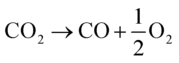
For all experimental runs reported here, time-integration of the measured O2 and CO evolution rates over each cycle confirmed a closed mass balance for 100% selectivity of CO2 to CO + 0.5O2, without any evidence of carbon deposition or any other by products.
Fig. 2 shows the nominal solar reactor temperature, the total pressure, and the specific O2 and CO evolution rates measured during two representative CO2-splitting redox cycles carried out under the combined temperature/pressure-swing mode. For comparison, both runs were performed under the same experimental conditions, except that either vacuum pressure (ptotal = 10 mbar with Ar = 0.625 L min−1; solid lines) or ambient pressure (ptotal = 1000 mbar with Ar = 7 L min−1; dashed lines) was applied during the reduction step. Consistent with Le Chatelier's principle, lowering ptotal by two orders of magnitude doubled the specific O2 evolution during reduction to 0.024 mol O2 per mol ceria (total 5.34 L, calculated by integration of the measured O2 evolution rate) at a peak rate of 0.4 mL min−1 gCeO2−1. Accordingly, the specific CO yield was twice that of O2 and attained a peak rate of 1.2 mL min−1 gCeO2−1. This in turn led to a significantly higher molar conversion of CO2 to CO, which could be effectively controlled by initiating oxidation through the injection of CO2 at a selected temperature Toxidation,start. This control strategy is put in practice in Fig. 3 for three cycles carried out under the same experimental condition, except that Toxidation,start = 700, 800, and 1000 °C. The instantaneous value of the CO2-to-CO molar conversion peaked at 83% for Toxidation,start = 700 °C, and decreased in time asymptotically as δ approached its thermodynamic equilibrium, as shown in Fig. 3a. The cumulative CO2-to-CO molar conversion, calculated by integration of the measured CO evolution rate over time – equivalent to the purity of CO in the product gas collected – attained a peak value of 65% before oxidation was completed, as seen in Fig. 3b along with the specific CO yield. Thus, for controlling the fuel purity, the oxidation can be interrupted by stopping injection of CO2 at a selected temperature Toxidation,end but at the expense of a lower CO yield. The trade-off between fuel purity and fuel yield is intrinsic to the dynamics of the oxidation step; optimization will be contingent upon the downstream processing of the fuel and the economics of the entire solar plant.
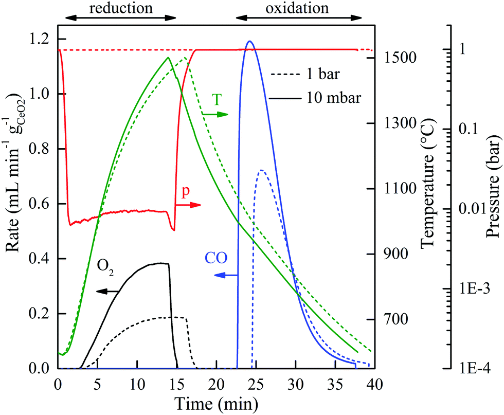 | ||
| Fig. 2 CO2-splitting redox cycles carried out under a combined temperature/pressure-swing operational mode. Nominal solar reactor temperature, total pressure, and specific O2 and CO evolution rates during two representative CO2-splitting redox cycles carried out at ptotal = 10 mbar and Ar = 0.625 L min−1 (solid lines) or ptotal = 1000 mbar and Ar = 7 L min−1 (dashed lines) applied during the reduction step. Experimental conditions during reduction: Psolar = 3.5 kW, Treduction = 1500 °C. Experimental conditions during oxidation: Psolar = 0 kW, Toxidation,start = 1000 °C, Toxidation,end = 600 °C, CO2 = 7 L min−1 at ptotal = 1 bar. | ||
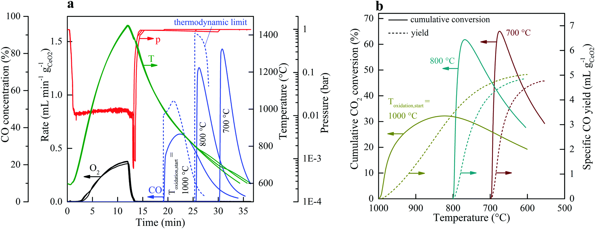 | ||
| Fig. 3 Strategy for controlling the CO2-to-CO conversion. (a) Nominal solar reactor temperature, total pressure, specific O2 and CO evolution rates, CO concentration (solid lines) and the corresponding thermodynamic limit (dashed lines) during three CO2 splitting cycles with varying Toxidation,start. (b) Cumulative CO2-to-CO molar conversion and specific CO yield vs. reactor temperature for the three cycles of (a). Experimental conditions during reduction: Psolar = 3.5 kW, Treduction = 1450 °C, Ar = 0.625 L min−1, and ptotal = 10 mbar. Experimental conditions during oxidation: Psolar = 0 kW, CO2 = 3 L min−1, ptotal = 1 bar, and Toxidation,start = 1000, 800, and 700 °C. | ||
As anticipated by thermodynamic analyses,31,32 increasing the mass flow rate of the inert gas affected negatively ηsolar-to-fuel because both Qinert and Qpump increased monotonically with Ar and additional energy was wasted for heating a larger Ar flow to the desired Treduction (ref. 50, Fig. S1, ESI†). Still, when operating under vacuum pressures, a minimum purge gas flow of about 0.625 L min−1 was required to govern the fluid flow field. We explored the possibility of completely eliminating the inert gas consumption by using instead ambient air as the purging gas at the same minimum flow rate for the run at ptotal = 10 mbar, resulting in analogous results to those employing Ar purging (ref. 50, Fig. S3, ESI†). The concentration of O2 in the outlet gas collected during the reduction step was 69.6%, the remainder being N2 and the other gaseous species in ambient air. In principle, purging with steam is thermodynamically favorable at ptotal = 10 mbar; after condensation, it would yield pure O2 as a valuable by-product.
The overall kinetics of the redox cycle were controlled by heat and mass transfer within the solar reactor and not by solid-state diffusion within the crystal lattice of ceria. Specifically, the reduction step was limited by the rate of radiative heat transfer, as verified by the experimentally determined δ(t), i.e. the time-integrated O2 evolution rate, that matched δ at equilibrium for the measured T and pO2, consistent with previous findings.26 This was indeed expected from the measured values of ambipolar diffusion coefficients of oxygen in ceria,33 in the range 1.5×10⁻⁵–4×10⁻⁴ cm2 s−1 for 1400–1550 °C, which translated to reduction times in the order of milliseconds for the length scales given by the RPC's porous struts. High-flux radiation, entering through the cavity's aperture at C >3000 suns, was volumetrically absorbed by the RPC, as predicted by its effective extinction coefficient of 497.8 m−1, calculated by collision-based Monte Carlo ray tracing at the pore level on the exact 3D digital geometry obtained by computer tomography.34 Radiative absorption was further augmented by the surface reflectivity of ceria decreasing with the nonstoichiometry as reduction progressed.35 In contrast, for the oxidation step, the measured δ(t) fell short of its equilibrium value as confirmed by the thermodynamic limit curves in Fig. 3a, consistent with solar-driven thermogravimetric measurements performed on the same RPC exposed to high-flux irradiation.36 Presumably, oxidation rates were limited by gas-phase mass transport limitations as well as hindered by reversible lattice compression, as evidenced by Raman spectroscopy.37
Stability
The solar reactor displayed a stable temperature/vacuum-swing mode of operation without observable degradation. Fig. 4a shows the nominal solar reactor temperature, total pressure, and specific O2 and CO evolution rates of five consecutive cycles. In Fig. 4b, the cycles #2, 3, 4 and 5 are also plotted on top of each other to corroborate excellent repeatability of both heating and reaction rates. Long-term stability of the RPC was demonstrated in 500 consecutive redox cycles using an IR furnace that enabled tight temperature control and rapid cycling (ref. 50, Fig. S4 and S5, ESI†). The O2 yield was constant throughout the cycling (Δδ = 0.031), attributed to the stable oxygen exchange capacity of ceria, provided that its fluorite-type crystallography is not altered.11 Scanning micrographs before and after the 500 consecutive redox cycles (ref. 50, Fig. S6, ESI†) revealed that the μm-sized pores within the struts of the RPC were preserved. Cracks within the grains were formed but they did not disturb the redox performance, as confirmed by the constant Δδ. Although the RPC remained intact, the effect of these cracks on the structure's strength is unknown. It was found that the fabrication methodology (e.g. particle size, slurry composition, pore-forming concentration, and the sintering protocol) could strongly affect the structural integrity of the RPC.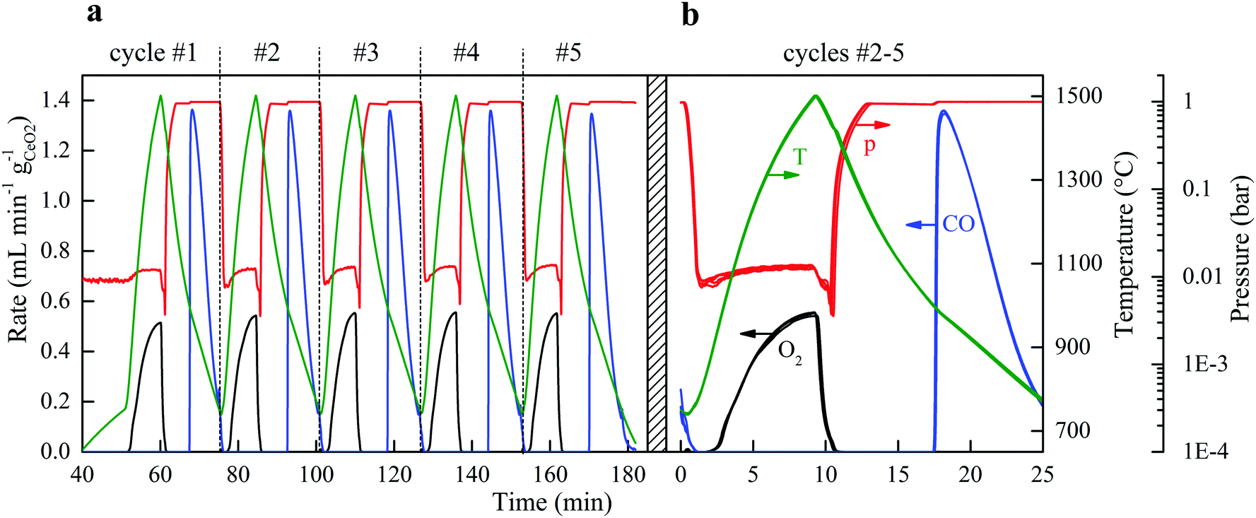 | ||
| Fig. 4 Consecutive cycles yielding a solar-to-fuel energy efficiency of 5.25%. (a) Nominal solar reactor temperature, total pressure, and specific O2 and CO evolution rates during 5 consecutive CO2-splitting redox cycles performed under a temperature/pressure-swing operational mode. Experimental conditions during reduction: Psolar = 4.1 kW, Treduction = 1500 °C, Ar = 0.625 L min−1 at ptotal = 10 mbar. Experimental conditions during oxidation: Psolar = 0 kW, Toxidation,start = 1000 °C, Toxidation,end = 750 °C, CO2 = 7 L min−1 at ptotal = 1 bar. (b) Cycles #2, 3, 4, and 5 of (a), plotted on top of each other. | ||
Energy efficiency
For each of the cycles #2, 3, 4, and 5 of Fig. 4b, ηsolar-to-fuel = 5.25% (standard deviation: 0.04%). A detailed energy balance reveals the partition of the total input energy (Qinput = Qsolar + Qinert + Qpump) and guides the path forward for future developments. The reaction enthalpy for the reduction of ceria (eqn (2); ΔH ≈ 475 kJ per mole of atomic oxygen) amounted to 8.8% of Qinput, which is higher than ηsolar-to-fuel because of the exothermic oxidation (eqn (3); ΔH ≈ −192 kJ per mole). The heat rejected can be recovered, as explained in the next paragraph. The energy penalty due to vacuum pumping was only 2.4% of Qinput because of the moderate vacuum pressure level applied (ptotal ≥ 10 mbar), which was enough to induce the desired δred − δox. The pressure drop across the 25 mm-thick RPC was negligible (<0.1 mbar), as estimated from the values of the effective permeability (4.6310−8 m2) and Dupuit−Forchheimer coefficient (1.62104 m−1) obtained by fitting Darcy's law to the solution of the Navier–Stokes equations on the 3D tomographic scans.34 The energy penalty due to inert gas consumption was only 0.6% of Qinput because of the low mass flow rate (0.625 L min−1) used during the reduction step, but even this penalty can in principle be eliminated by replacing Ar with ambient air as proved experimentally. Re-radiation through the aperture amounted to 9.5% of Qinput and thereby smaller than estimated for isothermal cycling15–17 because the nominal reactor temperature was below Treduction for the most part of the reduction step. It may be further lowered by operating at a higher solar flux concentration C (see eqn (1)), which can be achieved by incorporating a non-imaging secondary concentrator at the cavity's aperture, e.g. a compound parabolic concentrator,8 which enables the same Psolar through a smaller aperture size. Attenuation by the window, i.e. reflection and absorption, accounted for 6.6% of Qinput, which may be reduced to some extent by selective coatings. Conduction heat losses amounted to 9.3% of Qinput, which can be readily reduced by scaling up because of the lower surface-to-volume ratio. Moreover, conductive losses can even be eliminated by using an array of solar reactor modules arranged side-by-side, each attached to hexagon-shaped CPCs in a honeycomb configuration. Such a scale-up concept for a solar tower would also enable the capture of spilled radiation by the concentrating heliostat field. Further assembling the array of solar reactor modules in at least two clusters and focusing the heliostat field alternately onto each cluster would enable the simultaneous and continuous operation of both redox steps of the cycle without interruption of the incident solar radiative power.The dominant source of irreversibility of the cycle was due to the heating phase during the switch from the oxidation at Toxidation to the reduction at Treduction, requiring 62.8% of Qinput. This fraction can be significantly lowered by heat recovery via thermal energy storage. Storing high-temperature heat for subsequent re-use can be integrated in the cyclic process, for example by using a thermocline-based packed bed of rocks, which has been already demonstrated at the 6.5 MWhth pilot scale.38 By using two of these units in series and placing the solar reactor between them, two opposite mirror-like thermoclines with the hot side connected to the solar reactor can be established and shifted back-and-forth by the heat transfer fluid to recuperate a significant portion of the sensible heat during cooling from Treduction to Toxidation and deliver it back during heating from Toxidation to Treduction.39 Recovering only half of it would potentially boost ηsolar-to-fuel to values exceeding 20%.40,41 In this study, no attempt was undertaken to recover the sensible heat rejected during the temperature-swing cycling.
Alternative redox materials, e.g. doped ceria42,43 and perovskites,44–47 are being assessed for superior redox performance. Although some of these materials exhibit higher δred − δox compared to undoped ceria at the same Treduction and pO2, oxidation with CO2 is thermodynamically less favorable, leading to lower specific fuel productivity. Indeed, specific CO yields of undoped CeO2 can only be surpassed by using high amounts of excess CO2 and/or by operating at much lower Toxidation, both approaches implying additional energy penalties to heat excess CO2 and/or to overcome larger temperature differences between the redox steps, ultimately resulting in lower ηsolar-to-fuel compared to ceria under most conditions.42,47 Besides, excess CO2 disturbs the fuel purity. As far as the chemical stability is concerned, irreversible changes such as the formation and eventual segregation of carbonate phases are undesired even to low extents in view of prolonged cyclic operation.48 Thus, the quest for superior redox materials continues, but in the meantime, ceria is already proven to be a suitable and reliable one.
4. Conclusions
In sum, the stable and efficient splitting of CO2 into CO and O2 was accomplished via ceria redox cycling carried out under a temperature/pressure-swing operational mode. Crucial to this demonstration is an optimized solar cavity-receiver configuration containing a scalable porous RPC structure made of ceria with dual-scale porosity, which exhibited stability, robustness, and enhanced heat and mass transport properties for rapid reaction kinetics of both redox steps. The measured solar-to-fuel energy efficiency of 5.25% is comparable to the highest value reported to date (using a PV-electrolyzer3), with the additional benefit of total selectivity and high fuel purity. It also represents a boost by a factor of 3 from the next highest reported value to date by a thermochemical redox cycle,28 mainly due to the optimized reactor configuration and the significantly lower energy penalty of vacuum pumping as compared to that of inert gas recycling for maintaining a low pO2 value during the reduction. Higher efficiencies are readily possible by partial heat recovery, scaling up, and other practical measures elucidated by the energy balance. If methanol or Fischer–Tropsch fuels (e.g. kerosene) are the final target, an overall system efficiency (including downstream processing) of 7% would make the solar thermochemical path economically competitive vis-à-vis other renewable production paths,6 and the impact on climate would be negligible with provision of CO2 by air capture or from biogenic sources,49 making this approach truly sustainable for the production of liquid hydrocarbon fuels for the transportation sector, especially for aviation. Moreover, its large-scale industrial implementation, e.g. by means of an array of solar reactor modules on top of a solar tower, can make use of the solar concentrating infrastructure already developed for commercial CSP plants.Acknowledgements
This work was funded in part by the Swiss National Science Foundation (No. 200021-162435), the Swiss Federal Office of Energy (No. SI/501213-01), the European Commission (SOLAR-JET – No. 285098), and the European Research Council under the European Union's ERC Advanced Grant (SUNFUELS – No. 320541). We thank the technical staff of the Professorship of Renewable Energy Carriers for supporting the experimentation at the High-Flux Solar Simulator.References
- G. A. Ozin, Adv. Mater., 2015, 27, 1957–1963 CrossRef CAS PubMed.
- N. S. Lewis, Science, 2016, 351, aad1920 CrossRef PubMed.
- M. Schreier, et al. , Nat. Commun., 2015, 6, 7326 CrossRef CAS PubMed.
- Y. Sugano, et al. , RSC Adv., 2015, 5, 54246–54252 RSC.
- Z. Chen, et al. , Proc. Natl. Acad. Sci. U. S. A., 2012, 109, 15606–15611 CrossRef CAS PubMed.
- J. Kim, et al. , Energy Environ. Sci., 2012, 5, 8417–8429 CAS.
- M. Wenzel, et al. , AIChE J., 2017, 63, 15–22 CrossRef CAS.
- M. Romero and A. Steinfeld, Energy Environ. Sci., 2012, 5, 9234–9245 CAS.
- M. R. Singh, et al. , Proc. Natl. Acad. Sci. U. S. A., 2015, 112, E6111–E6118 CrossRef CAS PubMed.
- J. R. Scheffe and A. Steinfeld, Mater. Today, 2014, 17, 341–348 CrossRef CAS.
- W. C. Chueh and S. M. Haile, Philos. Trans. R. Soc., A, 2010, 368, 3269–3294 CrossRef CAS PubMed.
- S. Abanades and G. Flamant, Sol. Energy, 2006, 80, 1611–1623 CrossRef CAS.
- R. J. Panlener, et al. , J. Phys. Chem. Solids, 1975, 36, 1213–1222 CrossRef CAS.
- C. L. Muhich, et al. , Science, 2013, 341, 540–542 CrossRef CAS PubMed.
- R. Bader, et al. , Energy Fuels, 2013, 27, 5533–5544 CrossRef CAS.
- I. Ermanoski, et al. , Phys. Chem. Chem. Phys., 2014, 16, 8418–8427 RSC.
- L. J. Venstrom, et al. , Energy Fuels, 2014, 28, 2732–2742 CrossRef CAS.
- W. C. Chueh, et al. , Science, 2010, 330, 1797–1801 CrossRef CAS PubMed.
- P. Furler, et al. , Energy Environ. Sci., 2012, 5, 6098–6103 CAS.
- M. Roeb, et al. , Sol. Energy, 2011, 85, 634–644 CrossRef CAS.
- R. B. Diver, et al. , J. Sol. Energy Eng., 2008, 130, 041001 CrossRef.
- J. Lapp, et al. , J. Sol. Energy Eng., 2013, 135, 031004 CrossRef.
- M. Welte, et al. , Ind. Eng. Chem. Res., 2016, 55, 10618–10625 CrossRef CAS PubMed.
- I. Ermanoski, et al. , J. Sol. Energy Eng., 2013, 135, 031002 CrossRef.
- S. Brendelberger and C. Sattler, Sol. Energy, 2015, 113, 158–170 CrossRef CAS.
- P. Furler, et al. , Energy Fuels, 2012, 26, 7051–7059 CrossRef CAS.
- P. Furler, et al. , Phys. Chem. Chem. Phys., 2014, 16, 10503–10511 RSC.
- D. Marxer, et al. , Energy Fuels, 2015, 29, 3241–3250 CrossRef CAS.
- U. Ash-Kurlander, et al. , Energy Technol., 2016, 4, 565–572 CrossRef CAS.
- P. Furler and A. Steinfeld, Chem. Eng. Sci., 2015, 137, 373–383 CrossRef CAS.
- P. T. Krenzke and J. H. Davidson, Energy Fuels, 2015, 29, 1045–1054 CrossRef CAS.
- M. Lin and S. Haussener, Energy, 2015, 88, 667–679 CrossRef CAS.
- S. Ackermann, et al. , J. Phys. Chem. C, 2014, 118, 5216–5225 CAS.
- S. Ackermann, et al. , Int. J. Heat Mass Transfer, 2017, 107, 439–449 CrossRef CAS.
- S. Ackermann and A. Steinfeld, Sol. Energy Mater. Sol. Cells, 2017, 159, 167–171 CrossRef CAS.
- M. Takacs, et al. , AIChE J. DOI:10.1002/aic.15501.
- S. Ackermann, et al. , J. Phys. Chem. C, 2015, 119, 16452–16461 CAS.
- G. Zanganeh, et al. , Sol. Energy, 2012, 86, 3084–3098 CrossRef.
- A. Steinfeld, P. Furler, A. Haselbacher and L. Geissbühler, Eur. Pat. Appl. Nr. EP16194074, 2016 Search PubMed.
- J. R. Scheffe and A. Steinfeld, Energy Fuels, 2012, 26, 1928–1936 CrossRef CAS.
- J. Lapp, et al. , Energy, 2012, 37, 591–600 CrossRef CAS.
- M. Takacs, et al. , Phys. Chem. Chem. Phys., 2015, 17, 7813–7822 RSC.
- B. Bulfin, et al. , J. Phys. Chem. C, 2016, 120, 2027–2035 CAS.
- J. R. Scheffe, et al. , Energy Fuels, 2013, 27, 4250–4257 CrossRef CAS.
- A. H. McDaniel, et al. , Energy Environ. Sci., 2013, 6, 2424–2428 CAS.
- S. Dey, et al. , Phys. Chem. Chem. Phys., 2015, 17, 122–125 RSC.
- M. Takacs, et al. , Acta Mater., 2016, 103, 700–710 CrossRef CAS.
- M. E. Galvez, et al. , Phys. Chem. Chem. Phys., 2015, 17, 6629–6634 RSC.
- C. Falter, et al. , Environ. Sci. Technol., 2016, 50, 470–477 CrossRef CAS PubMed.
- ESI† is available in the online version of the paper, Fig. S1–S6.
Footnote |
| † Electronic supplementary information (ESI) available. See DOI: 10.1039/c6ee03776c |
| This journal is © The Royal Society of Chemistry 2017 |