
 Open Access Article
 This Open Access Article is licensed under a
 Creative Commons Attribution 3.0 Unported Licence
Electrodeposition of zinc nanoplates from an ionic liquid composed of 1-butylpyrrolidine and ZnCl2: electrochemical, in situ AFM and spectroscopic studies†
Giridhar
Pulletikurthi
*,
Maryam
Shapouri Ghazvini
,
Tong
Cui
,
Natalia
Borisenko
*,
Timo
Carstens
,
Andriy
Borodin
and
Frank
Endres
*
Institute of Electrochemistry, Clausthal University of Technology, Arnold-Sommerfeld-Str. 6, 38678, Clausthal-Zellerfeld, Germany. E-mail: giridhar.pulletikurthi@tu-clausthal.de; natalia.borissenko@tu-clausthal.de; frank.endres@tu-clausthal.de
First published on 1st December 2016
Abstract
The mixtures of 1-butylpyrrolidine and ZnCl2 result in the formation of an ionic liquid, which can be used as an electrolyte for zinc electrodeposition. The feasibility of electrodepositing Zn from these electrolytes was investigated at RT and at 60 °C. The synthesized mixtures are rather viscous. Toluene was added to the mixtures to decrease the viscosity of the ILs. Vibrational spectroscopy was employed for the characterization of the liquids. The electrochemical behaviour of the liquids was evaluated by cyclic voltammetry. The electrode/electrolyte interface of this IL was probed by Atomic Force Microscopy (AFM). The suitable range for the electrodeposition of Zn was found to be ≥28.6 mol% of ZnCl2. Zn deposition occurs mainly from the cationic species of [ZnClxLy]+ (where x = 1, y = 1–2, and L = 1-butylpyrrolidine) in these electrolytes. This is in contrary to the well investigated chlorozincate ionic liquids where the deposition of Zn occurs mainly from anionic chlorozincates. Nanoplates of Zn were obtained from these mixtures of 1-butylpyrrolidine and ZnCl2.
Introduction
Nanomaterials possess interesting structures and properties owing to their small sizes in the nanometer regime. Furthermore, metal nanoplates are of interest due to their promising catalytic, optical, and electronic properties.1 Among the various shapes, nanoplates possess sharp corners and edges that are supposed to be more active for certain applications.2 Furthermore, anisotropic materials (or particles) find special interest owing to their difference in quantum confinement in various dimensions, which occurs on the miniaturization of the particles.3 In particular, zinc nanostructures have a number of applications in the Zn redox battery, Zn–air fuel cell, and in the preparation of zinc oxide. Zinc nanoplates are prepared by some special techniques such as solid–vapour synthesis, electron-beam irradiation, thermal evaporation, chemical vapour deposition etc.4,5 The nanoplates synthesized by the aforementioned routines are always mixed with nanostructures having different morphologies. These routines need special conditions of operation. Furthermore, pure nanoplates without the mixture of other morphologies are rarely obtained. Thus, it is desirable to prepare phase pure zinc nanoplates with a uniform thickness by a template-free electrodeposition.Ionic liquids (ILs) are one of the most extensively investigated topics at present due to their applications in numerous fields.5–9 Initial interest in these liquids was mostly due to the electrodeposition of Al and their potential use in battery applications. The ionic liquids studied were formerly composed of organic salts like N-alkylpyridinium halides (or 1,3-dialkylimidazolium halides) and metal halides like AlCl3.10–13 These liquids contain anions like [AlCl4]− or [Al2Cl7]− and organic cations. In the past two decades, the research was focused on the replacement of the moisture sensitive chloroaluminate anion by discrete anions like e.g. trifluoromethylsulfonate, bis(trifluoromethylsulfonyl)amide, and many more.14,15 These ILs have been used for the electrodeposition of metals/semiconductors, battery applications, and in electrochemical devices.16–20 The electrodeposition of metals in such liquids occurs mainly from anionic species. For example, the electrodeposition of Al occurs from [AlCl2(TFSA)2]− in AlCl3/[Py1,4]TFSA and zinc electrodeposition occurs from [Zn(TfO)x]n− (where x = 4–5 and n = 2–3) in Zn(TfO)2/[Py1,4]TfO.21–24 The cations of ionic liquids together with anionic metal ion species may be present at the electrode/electrolyte interface, and the IL cations may influence or compete with metal-containing anionic species under the electrodeposition conditions.25 Furthermore, higher concentrations of metal complexes can be achievable in this kind of liquids by avoiding the accumulation of organic cations.26 Thus, it may be desirable to synthesize metal-containing cationic species to avoid this issue for metal plating applications.
Recently, a new class of electrolytes was proposed for metal plating applications. For example, the electrodeposition of Al from mixtures composed of amides, simple tertiary amines (1-butylpyrrolidine) or alkyl substituted pyridines (or dialkylsulfides) and AlCl3.27–29 For instance, some amide complexes of either AlCl3 or ZnCl2 were prepared by Abbott et al. for the electrodeposition of either Al or zinc, respectively.27,30 This new class of liquids are also classified as ionic liquids (they contain metal cations and anions), due to their ionic conductivity and similar physical properties, which are formed by the asymmetric cleavage of metal halides in the presence of ligands or due to the autoionization of metal halides under the influence of ligands. The presence of metal cationic complexes at the electrode/electrolyte interface seems to be a significant factor in influencing the deposition.25 Cationic complexes are still less common compared to anionic complexes in ionic liquids.31
In comparison, the mixtures of organic halide/ZnCl2, e.g. 1,3-alkylimidazolium chloride/ZnCl2, contain a number of anionic complexes such as [ZnCl3]−, [Zn2Cl5]−, [Zn3Cl7]− (or [ZnCl4]2−) and organic cations.32 However, the mixtures with neutral ligands (either amides or urea) and ZnCl2 show the presence of both anionic and cationic complexes like [ZnCl]+, [ZnCl(urea)]+, [ZnCl(urea)2]+ and [ZnCl(urea)3]+ and [ZnCl3]−. For acetamide/ZnCl2, [ZnCl(acetamide)2]+ and [ZnCl3]− were reported.30 It was assumed that the cleavage of ZnCl2 results in the formation of [ZnCl]+ and [ZnCl3]− and the equilibrium depends on the extent of stabilization of the cation with the ligand.30 However, the spectral characterization for ZnCl2/ligand systems has not yet been reported. Furthermore, to probe the electrode/electrolyte interface in this kind of liquids (ZnCl2/ligand), we have carried out Atomic Force Microscopy (AFM) experiments. Thus, in an effort to synthesize and characterize the species consisting of metal complexes as counter ions, a new liquid was prepared by mixing ZnCl2 with 1-butylpyrrolidine. Furthermore, the feasibility of Zn electrodeposition from this mixture, a spectroscopic characterization by vibrational spectroscopy and microscopic characterization by atomic force microscopy will be reported.
Results and discussion
Far-IR spectroscopy is used to probe cation–anion interactions in ILs.33 The far-IR spectra of the neat liquid and its mixtures with ZnCl2 (the mol ratio of ZnCl2 was varied from 0.4 to 0.75) are shown in Fig. 1a. There are no clear peaks in the regime between 100 and 450 cm−1 for 1-butylpyrrolidine. Metal–chloride (M–Cl) and metal–ligand (M–L) bonds can be observed in this far-IR region usually between 100 and 500 cm−1.34 Upon adding ZnCl2 to 1-butylpyrrolidine, a few distinct peaks were noticed in this regime. These new peaks can be related to the complexation of ZnCl2 with 1-butylpyrrolidine. The bands between 100 and 150 cm−1 can be assigned to Cl–Zn–Cl bending vibrations. A shoulder was observed at ∼190 cm−1, which could be attributed to the interaction of ZnCl2 with the nitrogen atom of the ligand. The metal–nitrogen–halide vibrational modes appear in the regime from 170 to 260 cm−1. The vibrational bands for ZnCl42− were reported in the literature, which are found to occur at ∼82 (Cl–Zn–Cl symmetric deformation, ν2), ∼130 (Cl–Zn–Cl asymmetric deformation, ν4) and ∼275 cm−1 (asymmetric stretching mode, ν3).35,36 Four signals were observed in our spectra in the regime between 100 and 350 cm−1 at 72, 126, 290 and 305 cm−1 for 1![[thin space (1/6-em)]](https://www.rsc.org/images/entities/char_2009.gif) :0.4 and 1:0.5 mol ratios of (1-butylpyrrolidine:ZnCl2). The peaks at 72, 132 and 290 cm−1 can be attributed to the vibrational modes of Zn–Cl. However, we cannot allocate these peaks solely to [ZnCl4]2− as we have observed the major peak at 290 cm−1 instead of 275 cm−1, and the allocation of these modes of vibrations is difficult with IR spectroscopy alone, as [ZnCl3]− also has to be expected. The peak intensity decreases with a decrease in the concentration of ZnCl2. Two shoulders are found at ∼198 and 250 cm−1 in the spectra for a 1:0.75 molar ratio of N-butylpyrrolidine:ZnCl2, which are correlated to Zn–N stretching vibrations.34,37 Quite a strong peak at 305 cm−1 along with two medium intensity peaks at 450 and 503 cm−1 was observed in all spectra. These peaks can be correlated to the interaction of the ligand with ZnCl2.34,38,39 For further analysis, Raman spectroscopy investigations were performed to obtain information on the nature of species. Previously, the analysis of such species was based on the assignment of mass spectroscopy data, which can lead to misleading results for the identification of halometallate ions and coordination compounds.26 To address this issue, Raman spectroscopy is an excellent tool to analyze the ionic species in these types of mixtures. Raman spectra can also sensitively reveal changes in molecular symmetry and are thus suited to the identification of species. Furthermore, the intensities of the Raman lines can be used to empirically relate the concentrations of species and one can calculate the solvation number of metal ions. The Raman spectra of the neat ligand and its mixtures with ZnCl2 at various mol ratios are shown in Fig. 1b.
:0.4 and 1:0.5 mol ratios of (1-butylpyrrolidine:ZnCl2). The peaks at 72, 132 and 290 cm−1 can be attributed to the vibrational modes of Zn–Cl. However, we cannot allocate these peaks solely to [ZnCl4]2− as we have observed the major peak at 290 cm−1 instead of 275 cm−1, and the allocation of these modes of vibrations is difficult with IR spectroscopy alone, as [ZnCl3]− also has to be expected. The peak intensity decreases with a decrease in the concentration of ZnCl2. Two shoulders are found at ∼198 and 250 cm−1 in the spectra for a 1:0.75 molar ratio of N-butylpyrrolidine:ZnCl2, which are correlated to Zn–N stretching vibrations.34,37 Quite a strong peak at 305 cm−1 along with two medium intensity peaks at 450 and 503 cm−1 was observed in all spectra. These peaks can be correlated to the interaction of the ligand with ZnCl2.34,38,39 For further analysis, Raman spectroscopy investigations were performed to obtain information on the nature of species. Previously, the analysis of such species was based on the assignment of mass spectroscopy data, which can lead to misleading results for the identification of halometallate ions and coordination compounds.26 To address this issue, Raman spectroscopy is an excellent tool to analyze the ionic species in these types of mixtures. Raman spectra can also sensitively reveal changes in molecular symmetry and are thus suited to the identification of species. Furthermore, the intensities of the Raman lines can be used to empirically relate the concentrations of species and one can calculate the solvation number of metal ions. The Raman spectra of the neat ligand and its mixtures with ZnCl2 at various mol ratios are shown in Fig. 1b.
 | ||
| Fig. 1 (a) Far-IR spectra of neat 1-butylpyrrolidine and its mixtures with various mol ratios of ZnCl2 (1:0.4 to 1:0.75), (b) Raman spectra of neat 1-butylpyrrolidine and its mixtures with various mol ratios of ZnCl2 (1:0.4 to 1:1). | ||
To interpret the Raman spectra, the peak positions of [ZnCl4]2−, [ZnCl3]−, ZnCl2 and 1-butylpyrrolidine were compared with literature data. The peaks originating from 1-butylpyrrolidine (black curve) are marked in Fig. 1b. A few strong Raman lines were observed for 1-butylpyrrolidine at ∼73, 313, 905, and 1450 cm−1.40–42 Two Raman vibrational bands were found at ∼80 and 130 cm−1, and these were attributed to Zn–Cl stretching modes.43 The vibrational mode of [ZnCl4]2− can be observed at ∼275 cm−1.44–46 The Raman vibration frequencies for [ZnCl3]− can be found at ∼285 and 348 cm−1.46 Furthermore, the Raman vibrational bands of ZnCl2 can be seen at ∼305 cm−1.46–48 In the Raman spectra of 1-butylpyrrolidine:ZnCl2, peaks/shoulders were observed at ∼80 and 116 for the 1:0.4 mol ratio (red curve) and at ∼82 and 120 cm−1 for the 1:0.5 mol ratio (green curve). Quite a broad peak was also noticed for these spectra at 290 cm−1. Upon increasing the concentration of ZnCl2 above the 0.5 mol ratio, the peak at 290 cm−1 shifted to lower wavenumbers to below 290 cm−1 for 1:0.75 (blue curve) along with a shoulder at around 276 cm−1. Furthermore, no clear peak was observed at 290 cm−1 for a 1:1 molar ratio of 1-butylpyrrolidine:ZnCl2 (wine curve), instead two shoulders were observed at ∼275 and 280 cm−1 for a 1:1 mol ratio of 1-butylpyrrolidine:ZnCl2. This indicates that at low concentrations of ZnCl2, the Zn(II) complex species are different from the species at higher concentrations of ZnCl2. Thus, below 1:0.75 molar concentrations of 1-butylpyrrolidine:ZnCl2, the anionic species might be [ZnCl3]− and above the 0.75 mol ratio of ZnCl2, the anionic species might be a mixture of [ZnCl3]− and [ZnCl4]2−. Furthermore, a new peak was observed at ∼305 cm−1, which might either be due to free ZnCl2 (or due to the solvated ZnCl2 species)47–49 and due to the mixture of ZnCl2 and [ZnCl]+, as the Raman bands for ZnCl2 and [ZnCl]+ could not be distinguished from each other.50
As the most significant changes were observed in the regions between 230 and 330 cm−1 in neat 1-butylpyrrolidine and its mixtures with ZnCl2, we have investigated this regime in more detail (Fig. 2). A clear peak was observed at 313 cm−1 in the neat ligand (black line), which can be attributed to the out-of-plane ring vibration mode of the ligand. This peak was shifted to below 300 cm−1 and the peak intensity was also found to decrease at this position upon complexation with ZnCl2. The lowering of the intensity and a shifting of the peak to <300 cm−1 can be attributed to the formation of a complex between the N-donor of the ligand and Zn2+. The average coordination number for the species can be determined from signals in this regime.
 | ||
| Fig. 2 Raman spectra of 1-butylpyrrolidine and its mixtures with ZnCl2 at various mol ratios in the regions from 245–340 cm−1. | ||
As observed from Fig. 2, the Raman peak of the neat ligand occurs at 313 cm−1. When adding various amounts of ZnCl2 to the ligand, broad waves/peaks appear between 260 and 350 cm−1. To obtain more information from the vibrational spectra, the Raman peaks were deconvoluted with Voigt functions. Fig. 3 shows the peak fits of the mixtures at various mol ratios of 1-butylpyrrolidine to ZnCl2. The raw data were deconvoluted into four/five components. From the peak fit analysis, the average coordination number (N) can be obtained by the following equation.51,52
 | (1) |
 | ||
| Fig. 3 Voigt fit components for the normalized Raman spectra at various mol ratios of 1-butylpyrrolidine and ZnCl2 in the regions from 200 to 400 cm−1. Peak positions of [ZnCl4]2−, [ZnCl3]−, and ZnCl2 are taken from the literature.44–48 | ||
The Raman spectra in Fig. 3a–d show the Voigt fit components of the spectra obtained for various mol ratios of 1-butylpyrrolidine:ZnCl2. In Fig. 3a, the best fit could be obtained by deconvoluting the spectrum into four components. For the other three spectra, the best fit could be obtained by deconvoluting the spectra into five components. The deconvoluted peaks and their respective components (Fig. 3a–d) might be attributed to [ZnCl4]2− (at 275 cm−1),44–46 [ZnCl3]− (at 285 cm−1),46 [ZnClLx]+ (at ∼294 cm−1), ZnCl2 (at 305 cm−1),47–49 1-butylpyrrolidine (at 313 cm−1), and [ZnCl3]− (at 350 cm−1).46 From the integral intensities of the fits, the average coordination number of Zn2+ can be obtained according to eqn (1). In the case of the 0.4:1 mol ratio of ZnCl2:1-butylpyrrolidine, one can fit the Raman spectrum with four peaks (Fig. 3a). The coordination number (N) calculated from eqn (1) for this mixture was found to be 2.2 (∼2). The N value for the 0.5:1 mol ratio of ZnCl2:1-butylpyrrolidine (Fig. 3b) was found to be 1.95 (∼2). The average N values for the 1:0.75 (Fig. 3c) and 1:1 (Fig. 3d) mol ratios of 1-butylpyrrolidine:ZnCl2 calculated from eqn (1) were 1.3 and ∼1, respectively. The number of ligands surrounding Zn2+ are found to be 2 and 1 for the range of compositions from 1:0.4 to 1:0.5 and 1:0.75 to 1:1 mol ratios of 1-butylpyrrolidine:ZnCl2, respectively.
From the spectral analysis, the species formed at various concentrations of ZnCl2 in 1-butylpyrrolidine can be suggested as follows. At lower concentrations of ZnCl2
| 2ZnCl2 + 2L → [ZnClL2]+ + [ZnCl3]− | (2) |
| 3ZnCl2 + 2L → 2[ZnClL]+ + [ZnCl3]− + [ZnCl4]2− | (3) |
From the vibrational spectral analysis the possible cationic Zn2+ complexes formed could be of the form [ZnClL2]+, [ZnClL]+, where L = 1-butylpyrrolidine. The possible anionic complexes of Zn2+ might be [ZnCl3]− and [ZnCl4]2−. Kurihara et al. investigated the complexation of Zn(II) ions with pyridine and with alkyl substituted pyridine in dimethylformamide.53 Based on calorimetric investigations, the authors reported the formation of [ZnL]2+ and [ZnL2]2+, where L = pyridine, 3-methylpyridine, or 4-methylpyridine.53
Cyclic voltammetry was employed to evaluate the electrochemical behaviour of the mixtures of 1-butylpyrrolidine and ZnCl2. A comparison of two cyclic voltammograms at two different mol ratios (1:0.4 and 1:0.5) of the mixtures at 60 °C is shown in Fig. 4. This figure also shows the CV of a 1:0.5 mol ratio of 1-butylpyrrolidine:ZnCl2 with 10 vol% toluene at RT. The CVs were carried out on Cu electrodes at a scan rate of 10 mV s−1. The potential of the electrode was scanned initially in the negative direction from the open circuit potential (OCP) to the chosen switching potential (vs. Zn). The CVs of 1-butylpyrrolidine:ZnCl2 (1:0.4 and 1:0.5) exhibit two reduction processes (C* and C1) in the forward scan and one major oxidation process (A1) in the reverse scan. The reduction process C* might be attributed to the alloy formation of Zn with Cu. The reduction process C1 is due to the deposition of Zn on Cu and its corresponding oxidation process is observed at A1. A similar electrochemical behaviour is also observed for the CV of a 1:0.5 mol ratio of 1-butylpyrrolidine:ZnCl2 with 10 vol% toluene at RT. The cyclic voltammograms of 1-butylpyrrolidine:ZnCl2 (1:0.75 and 1:1) mol ratios on Cu at 60 °C are shown in Fig. S1.† The CVs are characterized by one reduction process in the forward scan and a single oxidation process in the backward scan. The reduction process C1 is related to the deposition of Zn. Here at the high mol ratios of ZnCl2, we could not observe the formation of the Cu–Zn alloy. The process A1 is due to the dissolution of Zn. The reduction process of Zn2+ might be described as follows, where L = 1-butylpyrrolidine and x = 1–2. Abbott et al. reported that the oxidation process of Al in AlCl3/urea favours the formation of [AlCl2·urea]+.54
| [ZnClLx]+ + 2e− → Zn + Cl− + xL | (4) |
 | ||
| Fig. 4 Cyclic voltammograms of 1-butylpyrrolidine: ZnCl2 at two different mol ratios (1:0.4, red curve; 1:0.5, blue curve) at 60 °C, and 1:0.5 mol ratio of 1-butylpyrrolidine:ZnCl2 + 10 vol% toluene at RT (black curve). Working electrode: Cu; counter electrode: Zn; ν = 10 mV s−1. | ||
The viscosities at various mol ratios of 1-butylpyrrolidine and ZnCl2 are tabulated in Table S1 of the ESI.† The viscosities at 27 °C for the mol ratios of 1:0.4, 1:0.5, and 1:0.75 (1-butylpyrrolidine and ZnCl2) were found to be 256, 401.2, and 18443 mPa s, respectively. For instance, the viscosity of the mixture composed of urea and ZnCl2 (with a ratio of 3.5 of urea to ZnCl2, which corresponds to a 1:0.286 mol ratio of urea to ZnCl2) at 25 °C was found to be 11400 mPa s.30 A reduction in the viscosity of 1-butylpyrrolidine and ZnCl2 (1:0.4) in a comparable range to the composition of the urea and ZnCl2 mixture (1:0.286) could be related to the type of species formed and to their ionic sizes. The addition of 10 vol% toluene to the mixture of a 1:0.5 mol ratio of 1-butylpyrrolidine and ZnCl2 significantly decreases the viscosity to 117.5 mPa s. The viscosity values increase with an increase in the concentration of ZnCl2 in the mixtures, which could be related to the difference in the speciation, increase in charge carriers, and also to their sizes. Furthermore, such an increase in the viscosity with an increase in the concentration of the metal halide salt was observed for the mixtures prepared from 4-propylpyridine and AlCl3.25
In an attempt to describe the electrode/electrolyte interface (or the interfacial structure) of this electrolyte where cationic and anionic metal complexes are the constituent ions of the IL (i.e. IL formed by mixing a neutral ligand, 1-butylpyrrolidine and ZnCl2), we have performed Atomic Force Microscopy (AFM) investigations for the 1:0.5 mol ratio of 1-butylpyrrolidine:ZnCl2. To the best of the authors’ knowledge, such measurements have not been carried out for such systems so far to describe the interfacial structure of the ionic liquids containing metal complexes as constituent ions. Rather bad force–distance curves were obtained for the ZnCl2/1-butylpyrrolidine mixture presumably as a consequence of the viscosity. Thus, for subsequent AFM measurements, 10 vol% of toluene was added to decrease the viscosity. In order to know the electrochemical behavior and the spectral features of a 1:0.5 mol ratio of 1-butylpyrrolidine:ZnCl2 + 10 vol% toluene, we have also recorded the CV on gold and the Raman spectrum of this mixture. The corresponding CV and Raman spectra are shown in ESI, Fig. S2 and S3,† respectively. The Raman spectrum of a 1:0.5 mol ratio of 1-butylpyrrolidine:ZnCl2 + 10 vol% toluene has similar spectral features to that of a 1:0.5 mol ratio of 1-butylpyrrolidine:ZnCl2. Furthermore, in the spectrum two new peaks are observed at ∼225 and 525 cm−1, which are related to toluene.55 In the forward scan of the CV (Fig. 4), two reduction processes are observed. The reduction process (C*) might be attributed to the alloy formation of Zn with gold and the reduction process (C1) is attributed to the deposition of Zn, which occurs at ∼−0.5 V. A single oxidation process is observed in the backward scan, which can be related to the dissolution of Zn (A1).
Recently in situ atomic force microscopy (AFM) has become an important tool to probe the interfacial nanostructure on solid surfaces in various ILs.56 The solid–liquid interface in ILs is considerably different from conventional aqueous systems due to the difference in the solvent–solvent and solvent–solid interactions. Recent in situ AFM and in situ STM studies have shown that ILs arrange in an orderly layered structure at the solid–IL interface including on charged electrodes.57–60
The electrochemical behavior of the electrolyte does not change significantly with the addition of toluene (Fig. S2†). However, the interaction of toluene on the 1-butylpyrrolidine:ZnCl2/Au(111) interface cannot be completely excluded, as toluene can adsorb on the gold surface.61Fig. 5 shows the force versus separation curves for an AFM tip approaching an Au(111) surface in a 1:0.5 mol ratio of 1-butylpyrrolidine:ZnCl2 + 10 vol% toluene at various electrode potentials. The appearance of the AFM force curves differs significantly from the force curves reported for the IL/Au(111) interface.60,62 The measurements usually exhibit discrete force–distance curves, which can be explained by means of the size of the ions or of ion pairs, respectively. The steps in these AFM force curves are due to the expulsion of the interfacial liquid layers from the gold substrate. The push-through force increases closer to the surface as the ordering is more pronounced close to the interface. Thus, the step width usually corresponds to the dimension of the individual ionic species or ion pairs. In the case of 1-butylpyrrolidine:ZnCl2/Au(111), the interfacial structure is highly complex. Instead of the typical discrete force signals a broad signal is observed at the applied potentials at the interface (Fig. 5). This behavior reveals a strong ion–ion interaction between the solvation layers because due to the displacement of one of the solvation layers the AFM tip pulls the other layers as well. Such a strong ion–ion interaction should in turn reduce the ion–surface interaction. At the OCP (−0.5 V vs. Zn) three small steps, 0.48 nm, 0.53 nm and 0.71 nm, can be detected within a broad signal of ∼1.72 nm width (Fig. 5a). Several cationic ([ZnClL]+ and [ZnClL2]+), anionic ([ZnCl4]2−, [ZnCl3]−) and neutral (L = 1-butylpyrrolidine) species as well as toluene are in the electrolyte, which might affect/be present at the IL/Au(111) interface. Therefore, it is quite difficult to allocate each peak to the formation of a particular layer consisting of defined ionic species. Raman spectra reveal the formation of [ZnClLx=1–2]+ in the 1-butylpyrrolidine:ZnCl2 mixture. Therefore the innermost layer of 0.48 nm width can be related to the presence of the [ZnClLx=1–2]+ species at the interface. About 18 nN force is needed to rupture the innermost layer revealing that a relatively strong near surface structure is present. There is no significant change in the width of the broad peak at the IL/Au(111) interface by reducing the electrode potential. However, the number and the width of the small steps inside this broad peak change notably by decreasing the electrode potential indicating the rearrangement of the species at the interface. Thus, at +0.4 V, at least five small steps can be detected within the broad peak (Fig. 5b). The innermost layer is 0.48 nm wide, which might indicate the presence of [ZnClLx=1–2]+. The width of the innermost layer decreases significantly by further reducing the electrode potential: 0.28 nm step at −0.1 V (Fig. 5c) and 0.19 nm step at −0.2 V (Fig. 5d). From the CV the bulk deposition of Zn begins in the potential range between −0.1 V and −0.2 V. It is therefore possible that this narrow step is due to a breaking of the [ZnClLx=1–2]+ complex and formation of the [ZnCl]+ species. Furthermore, at more negative electrode potentials [ZnClLx=1–2]+ may adopt a flatter orientation to the surface that decreases the size of the ion.
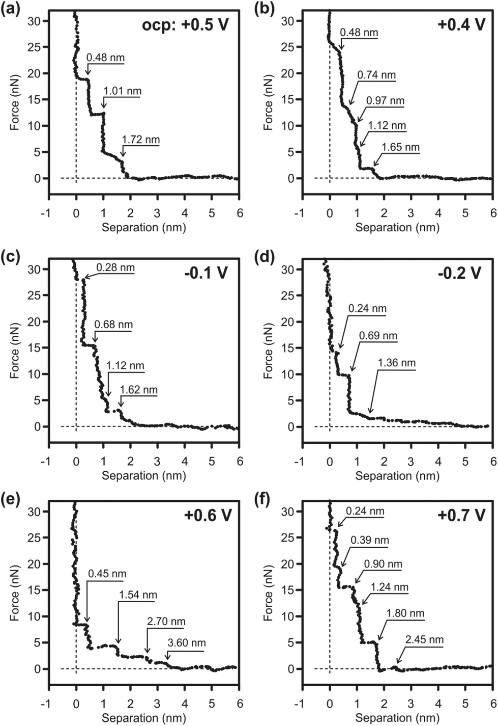 | ||
| Fig. 5 Force versus separation profile for an AFM tip approaching a Au(111) surface in buPy:ZnCl2 (1:0.5 molar ratio) with 10 vol% toluene (a) at the OCP, (b–d) at negative electrode potentials and (e, f) at positive electrode potentials. | ||
The appearance of the force curves changes significantly by applying a positive potential. At +0.6 V four wide solvation layers can be detected with the first step noticed at 3.6 nm (Fig. 5e). The innermost layer is 0.45 nm wide that, as in the case of the OCP, corresponds to a diameter of [ZnClLx=1–2]+. However, the force required to rupture the innermost layer decreases (∼8 nN) indicating that a weaker near surface structure is present likely due to a rearrangement of the ions at the interface. The widths of the following steps are ∼1.1 nm wide, possibly due to the formation of the [ZnClL+ − L − ZnCl3−] species. Bradbury et al. reported the IR spectra of complex ions of the type ZnCl3L− ([LMX3]−), where L = pyridine or triphenylphosphine, M = Co, Ni or Zn, and X = Cl− or Br−.63 At +0.7 V the innermost layer is 0.24 nm wide and the force to rupture the layer is markedly increased (∼27 nN). At this electrode potential both [ZnCl4]2− and [ZnCl3]− can be present at the surface (Fig. 5f). Furthermore, at more positive electrode potentials the decomposition of the anion cannot be completely excluded and the decomposition products might also alter the IL/Au(111) interface. In conclusion, in situ AFM results reveal that the 1-butylpyrrolidine:ZnCl2/Au(111) interfacial structure is rather complex and further investigations are needed to comprehensively describe the ionic arrangement at the interface.
In order to obtain zinc deposits, constant-potential electrolysis of the mixtures was carried out on Cu electrodes at −0.5 V and 60 °C for 2 h. For the mixture at a 1:0.5 mol ratio of 1-butylpyrrolidine:ZnCl2 + 10 vol% toluene, constant-potential electrolysis on Cu and gold electrodes was carried out at −0.5 V for 2 h at RT. The obtained deposits were washed in isopropanol and dried in the glove-box. The morphology and crystallinity of the Zn deposits have been investigated by scanning electron microscopy and X-ray diffraction, respectively. The morphologies of the Zn deposits on Cu at various mol ratios are shown in Fig. 6a–d. We could not find any remarkable differences in the morphologies of the deposits. The deposits consist of hexagonal Zn nanoplates with lateral dimensions of around 5–10 μm. The plate thickness was found to be rather thin. The dimensions of the plates decrease with an increase in the mol ratios of ZnCl2 in the mixtures. Dai et al. reported the growth of gold nanosheets in ILs based on pyrrolidinium cations with a bis(trifluoromethylsulfonyl)amide anion by a ionothermal reduction route.64 The growth mechanism of the zinc nanoplates is not yet understood and further investigations might be needed to know why this kind of preferred morphology is obtained from these mixtures. Interested readers are referred to ref. 65. Previously we obtained intertwined zinc nanowires by a template-free electrodeposition from an ionic liquid.66 Poly(vinylpyrrolidone), PVP, has been extensively used in the solution-phase synthesis of metal nanoplates, which can be considered as a steric stabilizer or capping agent to protect the metal nanoplates from agglomeration.2 Yuan et al. reported the growth and morphological characterization of Zn nanoplates and concluded that the intrinsic growth anisotropy of Zn is the driving force leading to the formation of the plate-like structures.4 For further understanding on the formation of nanostructures with various shapes, the reader is referred to ref. 67.
 | ||
| Fig. 6 SEM images of the Zn deposits obtained from various mol ratios of 1-butylpyrrolidine:ZnCl2 mixtures on Cu at 60° for 2 h. (a) 1:0.4, (b) 1:0.5, (c) 1:0.75, (d) 1:1. | ||
The deposition of Zn was carried out either on gold or on Cu to test whether we obtain Zn nanoplates or not from a 1:0.5 mol ratio of 1-butylpyrrolidine:ZnCl2 + 10 vol% toluene. The deposition of Zn on gold (or on Cu) from this solution was carried out at −0.5 V and at RT. The SEM images of Zn deposits on gold and on Cu are shown in Fig. S4 and S5,† respectively. Zinc nanoplates have been obtained on both substrates with almost similar lateral dimensions and thicknesses. This indicates that the substrate plays no major role in obtaining Zn nanoplates.
Fig. 7 shows typical XRD profiles of the zinc deposits obtained from the electrolysis of the mixtures at various mol ratios, carried out on Cu electrodes at −0.5 V and 60 °C for 2 h. The diffraction peaks of Zn deposits match with the peaks of the hexagonal structure of Zn (JCPDS 04-0831). The narrow and sharp diffraction peaks indicate that the obtained deposits are crystalline with particle sizes in the nanometer regime. A strong (002) plane is noticed in all diffractograms. Furthermore, at low mol ratios of ZnCl2, we noticed an alloy formation of Zn with Cu, which is suppressed by increasing the mol ratio of ZnCl2. The average crystal size was found to be 60–65 nm using the Scherrer equation.68 The XRD pattern of the Zn deposit obtained from a 1:0.5 mol ratio of 1-butylpyrrolidine:ZnCl2 with 10 vol% toluene at −0.5 V and RT is shown in the ESI (Fig. S5†). This pattern also matches with the hexagonal structure of Zn (JCPDS 04-0831). The crystal size in this is found to be 55–60 nm.
 | ||
| Fig. 7 XRD profiles of the Zn deposits obtained from various mol ratios of 1-butylpyrrolidine:ZnCl2 mixtures on Cu at 60° for 2 h. (a) 1:0.4, (b) 1:0.5, (c) 1:0.75, (d) 1:1. | ||
Conclusions
The mixture of 1-butylpyrrolidine and ZnCl2 results in the formation of a new IL, which is composed of zinc complexes as cations and anions. It was found that a minimum of 0.4 mol ratio of ZnCl2 is necessary to form a homogeneous mixture and below this concentration a biphasic mixture was obtained. Raman spectroscopy revealed the formation of an IL with zinc chloro complexes as constituent ions of the IL. The species formed in the mixtures could be [ZnClLx]+, [ZnCl3]− and [ZnCl4]2− depending on the concentration of ZnCl2 in 1-butylpyrrolidine. The average coordination number of the mixtures was calculated from the integral intensities of the Voigt fit components from the deconvoluted Raman spectra. It was found that the number of ligands coordinated to Zn2+ decreases with an increase in the concentration of ZnCl2 in 1-butylpyrrolidine. The electrode/electrolyte interface of this kind of new IL (1:0.5 mol ratio of 1-butylpyrrolidine:ZnCl2 + 10 vol% toluene) was investigated by in situ AFM. The innermost layer thickness suggests the presence of cationic complexes at the interface, and that the interfacial structure of this new type of IL is rather complicated. Zinc can be electrodeposited from these mixtures; nanoplates of Zn were obtained with a plate thickness in the nanometer regime from these electrolytes.
Experimental
1-Butylpyrrolidine was purchased from Sigma Aldrich, Germany. The purity of the as-received substance is 98% and was used without any further purification. ZnCl2 powder (98%) was procured from Fluka, Germany. The mixtures were prepared by careful mixing of 1-butylpyrrolidine and ZnCl2 in a glove-box. The weighed amounts of ZnCl2 were added to 1-butylpyrrolidine and stirred for 4 h. Various compositions were prepared from 1:1 to 0.25:1 molar ratios of ZnCl2 and 1-butylpyrrolidine. A biphasic mixture was obtained at 1:0.25 and 1:0.3 mol ratios of 1-butylpyrrolidine:ZnCl2. Rather viscous and clear liquids are obtained at 1:0.4 and 1:0.5 mol ratios of 1-butylpyrrolidine:ZnCl2. A viscous rather gel-like solid was obtained at mol ratios of 1:1 and 1:0.75 of 1-butylpyrrolidine:ZnCl2 with a dark yellowish colour. Clear yellow liquids were obtained at lower concentrations of ZnCl2.
The FT-IR measurements were performed with a Bruker Vertex 70 FT-IR spectrometer. The instrument was equipped with an extension for measurements in the far-IR region, which consists of a multilayer Mylar beam splitter, a room temperature DLATGS detector with a preamplifier and polyethylene (PE) windows for the internal optical path. The available spectral region for this configuration was between 30 and 680 cm−1. Raman measurements were carried out with a Raman module FRA 106 (Nd:YAG laser, 1064 nm) attached to a Bruker IFS 66v interferometer.
The viscosity measurements were performed at 27 °C with a microVISCTM viscometer from RheoSense (model number: microVISC TC: HVROC-T; serial number: microVISC TC: H1211-00156).
The electrochemical measurements were carried out using a PARSTAT 2263 potentiostat/galvanostat controlled by PowerCV and PowerStep software. Unless otherwise mentioned, Cu substrates were used as working electrodes (WE), and zinc sheets/wires were used as counter and reference electrodes. Prior to use the WEs were cleaned in acetone and dried. High resolution SEM (Carl Zeiss DSM 982 Gemini) was employed to investigate the morphology of the deposits. X-ray diffraction patterns were recorded at RT using a PANalytical Empyrean Diffractometer (Cabinet no. 9430 060 03002) with CuKα radiation. Force–distance curves were collected using a Molecular Imaging Pico Plus AFM in the contact mode. A silicon SPM-sensor from NanoWorld was employed for all experiments presented in this study. The spring constant was 6 N m−1 as given by the supplier. All force curves were acquired at room temperature in an argon-filled glove-box. For these measurements Au(111) (300 nm gold on mica) substrates purchased from Agilent Technologies were used as working electrodes. Pt wires were used as counter and reference electrodes, respectively. A Pt-wire has sufficient stability in the employed electrolytes throughout the in situ AFM measurements and gives a potential of about −0.3 V vs. a Zn wire. Toluene (99.99%) was purchased from Sigma Aldrich, Germany.
References
- H. Zhang, F. Li, Q. Xiao and H. Lin, J. Phys. Chem. Lett., 2015, 6, 2170–2176 CrossRef CAS PubMed.
- Y. Xiong, I. Washio, J. Chen, H. Cai, Z.-Y. Li and Y. Xia, Langmuir, 2006, 22, 8563–8570 CrossRef CAS PubMed.
- M. B. E. Griffiths, S. E. Koponen, D. J. Mandia, J. F. McLeod, J. P. Coyle, J. J. Sims, J. B. Giorgi, E. R. Sirianni, G. P. A. Yap and S. T. Barry, Chem. Mater., 2015, 27, 6116–6124 CrossRef CAS.
- X. Y. Luo, G. T. Tan, M. Y. Yuan, H. H. Wang, J. C. Zhang, Q. J. Jia and X. M. Jiang, Sci. China: Technol. Sci., 2012, 55, 2646–2650 CrossRef CAS.
- M. Armand, F. Endres, D. R. MacFarlane, H. Ohno and B. Scrosati, Nat. Mater., 2009, 8, 621–629 CrossRef CAS PubMed.
- W. Lu, A. G. Fadeev, B. Qi, E. Smela, B. R. Mattes, J. Ding, G. M. Spinks, J. Mazukiewicz, D. Zhou, G. G. Wallace, D. R. MacFarlane, S. A. Forsyth and M. Forsyth, Science, 2002, 297, 983–987 CrossRef CAS PubMed.
- G. G. Eshetu, M. Armand, B. Scrosati and S. Passerini, Angew. Chem., Int. Ed., 2014, 53, 13342–13359 CrossRef PubMed.
- M. Opallo and A. Lesniewski, J. Electroanal. Chem., 2011, 656, 2–16 CrossRef CAS.
- H. Olivier-Bourbigou, L. Magna and D. Morvan, Appl. Catal., A, 2010, 373, 1–56 CrossRef CAS.
- F. H. Hurley Jr. and T. P. Weir, J. Electrochem. Soc., 1951, 98, 203–206 CrossRef.
- F. H. Hurley Jr. and T. P. Weir, J. Electrochem. Soc., 1951, 98, 207–212 CrossRef.
- Y. Zhao and T. J. VanderNoot, Electrochim. Acta, 1997, 42, 1639–1643 CrossRef CAS.
- M. Lipsztajn and R. A. Osteryoung, J. Electrochem. Soc., 1983, 130, 1968–1969 CrossRef CAS.
- C. P. Fredlake, J. M. Crosthwaite, D. G. Hert, N. V. K. A. Sudhir and J. F. Brennecke, J. Chem. Eng. Data, 2004, 49, 954–964 CrossRef CAS.
- P. Bonhote, A.-P. Dias, N. Papageorgiou, K. Kalyanasundaram and M. Grätzel, Inorg. Chem., 1996, 35, 1168–1178 CrossRef CAS PubMed.
- S. Z. E. Abedin and F. Endres, ChemPhysChem, 2006, 7, 58–61 CrossRef PubMed.
- H. Sakaebo, H. Matsumoto and K. Tatsumi, Electrochim. Acta, 2007, 53, 1048–1054 CrossRef.
- V. Borgel, E. Markevich, D. Aurbach, G. Semrau and M. Schmidt, J. Power Sources, 2009, 189, 331–336 CrossRef CAS.
- D. R. MacFarlane, M. Forsyth, P. C. Howlett, J. M. Pringle, W. Neil and E. I. Izgorodina, Acc. Chem. Res., 2007, 40, 1165–1173 CrossRef CAS PubMed.
- S. Imaizumi, Y. Ohtsuki, T. Yasuda, H. Kokubo and M. Watanabe, ACS Appl. Mater. Interfaces, 2013, 5, 6307–6315 CAS.
- P. Eiden, Q. Liu, S. Z. E. Abedin, F. Endres and I. Krossing, Chem. – Eur. J., 2009, 15, 3426–3434 CrossRef CAS PubMed.
- N. M. Rocher, I. Izgorodina, T. Rüther, M. Forsyth, D. R. MacFarlane, T. Rodopoulos, M. D. Horne and A. M. Bond, Chem. – Eur. J., 2009, 15, 3435–3447 CrossRef CAS PubMed.
- T. Rodopoulos, L. Smith, M. D. Horne and T. Rüther, Chem. – Eur. J., 2010, 16, 3815–3826 CrossRef CAS PubMed.
- Z. Liu, S. Z. E. Abedin and F. Endres, ChemPhysChem, 2015, 16, 970–977 CrossRef CAS PubMed.
- Y. Fang, K. Yoshi, X. Jiang, X.-G. Sun, T. Tsuda, N. Mehio and S. Dai, Electrochim. Acta, 2015, 160, 82–88 CrossRef CAS.
- F. Coleman, G. Srinivasa and M. Swazba-Kwasny, Angew. Chem., Int. Ed., 2013, 52, 12582–12586 CrossRef CAS PubMed.
- H. M. A. Abood, A. P. Abbott, A. D. Ballantyne and K. S. Ryder, Chem. Commun., 2011, 47, 3523–3525 RSC.
- G. Pulletikurthi, B. Bödecker, A. Borodin, B. Weidenfeller and F. Endres, Prog. Nat. Sci.: Mater. Int., 2015, 25, 603–611 CrossRef CAS.
- Y. Fang, X. Jiang, X.-G. Sun and S. Dai, Chem. Commun., 2015, 51, 13286–13289 RSC.
- A. P. Abbott, J. C. Barron, K. S. Ryder and D. Wilson, Chem. – Eur. J., 2007, 13, 6495–6501 CrossRef CAS PubMed.
- D. Atwood, Coord. Chem. Rev., 1998, 176, 407–430 CrossRef CAS.
- S.-I. Hsiu, J.-F. Huang, I.-W. Sun, C.-H. Yuan and J. Shiea, Electrochim. Acta, 2002, 47, 4367–4372 CrossRef CAS.
- K. Fumino, A. Wulf and R. Ludwig, Angew. Chem., Int. Ed., 2008, 47, 3830–3834 CrossRef CAS PubMed.
- R. J. H. Clark and C. S. Williams, Inorg. Chem., 1965, 4, 350–357 CrossRef CAS.
- P. H. M. van Loosdrecht and A. Janner, J. Phys.: Condens. Matter, 1991, 3, 8113–8126 CrossRef CAS.
- W. Bues, Z. Anorg. Allg. Chem., 1955, 279, 104–114 CrossRef CAS.
- C. W. Frank and L. B. Rogers, Inorg. Chem., 1966, 5, 615–622 CrossRef CAS.
- S. N. Ghosh, J. Inorg. Nucl. Chem., 1973, 35, 2329–2334 CrossRef CAS.
- C. Postmus, J. R. Ferraro and W. Wozniak, Inorg. Chem., 1967, 6, 2030–2032 CrossRef CAS.
- N. D. Chizhikova, O. S. Anisimova, Y. A. Pentin and L. G. Yudin, J. Struct. Chem., 1969, 10, 520–523 CrossRef.
- F. Billes and E. Geidel, Spectrochim. Acta, Part A, 1997, 53, 2537–2551 CrossRef.
- J. C. Evans and J. C. Wahr, J. Chem. Phys., 1959, 31, 655–662 CrossRef CAS.
- G. Peyronel and A. Giusti, Spectrochim. Acta, Part A, 1981, 37, 71–75 CrossRef.
- N. Trendafilova, G. St. Nikolov, R. Kellner and G. Bauer, Vib. Spectrosc., 1994, 6, 351–362 CrossRef CAS.
- M. Scrocco, Spectrochim. Acta, Part A, 1977, 33, 357–360 CrossRef.
- D. F. C. Morris, E. L. Short and D. N. Waters, J. Inorg. Nucl. Chem., 1963, 25, 975–983 CrossRef CAS.
- Z. Kecki, Spectrochim. Acta, 1962, 18, 1165–1164 Search PubMed.
- D. E. Irish and T. F. Young, J. Chem. Phys., 1965, 43, 1765–1768 CrossRef CAS.
- H. Kanno and S. Yamauchi, J. Solution Chem., 1991, 20, 589–594 CrossRef CAS.
- M. Maeda, T. Ito, M. Hori and G. Johansson, Z. Naturforsch., A: Phys. Sci., 1996, 51, 63–70 CrossRef CAS.
- J. Pitawala, J.-K. Kim, P. Jacobsson, V. Koch, F. Croce and A. Matic, Faraday Discuss., 2012, 154, 71–80 RSC.
- G. A. Giffin, A. Moretti, S. Jeong and S. Passerini, J. Phys. Chem. C, 2014, 118, 9966–9973 CAS.
- M. Kurihara, K. Ozutsumi and T. Kawashima, J. Chem. Soc., Dalton Trans., 1993, 3379–3382 RSC.
- A. P. Abbott, R. C. Harris, Y.-T. Hsieh, K. S. Ryder and I.-W. Sun, Phys. Chem. Chem. Phys., 2014, 16, 14675–14681 RSC.
- J. K. Wilmshurst and H. J. Bernstein, Can. J. Chem., 1957, 35, 911–925 CrossRef CAS.
- R. Hayes, G. G. Warr and R. Atkin, Chem. Rev., 2015, 115, 6357–6426 CrossRef CAS PubMed.
- R. Hayes, G. G. Warr and R. Atkin, Phys. Chem. Chem. Phys., 2010, 12, 1709–1723 RSC.
- F. Endres, N. Borisenko, S. Z. E. Abedin, R. Hayes and R. Atkin, Faraday Discuss., 2012, 154, 221–233 RSC.
- R. Atkin, N. Borisenko, M. Drüschler, S. Z. E. Abedin, F. Endres, R. Hayes, B. Huber and B. Roling, Phys. Chem. Chem. Phys., 2011, 13, 6849–6857 RSC.
- R. Hayes, N. Borisenko, M. K. Tam, P. C. Howlett, F. Endres and R. Atkin, J. Phys. Chem. C, 2011, 115, 6855–6863 CAS.
- X. Gao, J. P. Davies and M. J. Weaver, J. Phys. Chem., 1990, 94, 6858–6864 CrossRef CAS.
- A. Lahiri, T. Carstens, R. Atkin, N. Borisenko and F. Endres, J. Phys. Chem. C, 2015, 119, 16734–16742 CAS.
- J. Bradbury, K. P. Forest, R. H. Nuttall and D. W. A. Sharp, Spectrochim. Acta, Part A, 1967, 23, 2701–2704 CrossRef CAS.
- C. Bouvy, G. A. Baker, H. Yin and S. Dai, Cryst. Growth Des., 2010, 10, 1319–1322 CAS.
- C. Lofton and W. Sigmund, Adv. Funct. Mater., 2005, 15, 1197–1208 CrossRef CAS.
- G. Pulletikurthi, M. S. Ghazvini, A. Prowald, S. Z. E. Abedin and F. Endres, ChemElectroChem, 2015, 2, 1366–1371 CrossRef CAS.
- Y. Xia, Y. Xiong, B. Lim and S. E. Skarbalak, Angew. Chem., Int. Ed., 2009, 48, 60–103 CrossRef CAS PubMed.
- P. Scherrer, Göttingen Nachr. Math. Phys., 1918, 2, 98–100 Search PubMed.
Footnote |
| † Electronic supplementary information (ESI) available. See DOI: 10.1039/c6dt04149c |
| This journal is © The Royal Society of Chemistry 2017 |