
 Open Access Article
 This Open Access Article is licensed under a Creative Commons Attribution-Non Commercial 3.0 Unported Licence
Graphene oxide layers modified by light energetic ions
Petr
Malinský
*a,
Anna
Macková
ab,
Romana
Mikšová
ab,
Helena
Kováčiková
ab,
Mariapompea
Cutroneo
a,
Jan
Luxa
c,
Daniel
Bouša
c,
Beata
Štrochová
c and
Zdeněk
Sofer
 *c
*c
aInstitute of Nuclear Physics AS CR, v.v.i., Husinec – Řež, 130, 250 68 Řež, Czech Republic. E-mail: malinsky@ujf.cas.cz
bDepartment of Physics, Faculty of Science, J.E. Purkinje University, Ceske Mladeze 8, 400 96 Usti nad Labem, Czech Republic
cDepartment of Inorganic Chemistry, University of Chemistry and Technology Prague, Technická 5, 166 28 Prague 6, Czech Republic. E-mail: zdenek.sofer@vscht.cz
First published on 15th March 2017
Abstract
In this paper, the effect of light ion irradiation on graphene oxide foil structure and composition was studied. Due to the excellent properties of graphene based materials suitable for application in electronics, optoelectronics, micro-mechanics and space technologies, the interaction of energetic ions with graphene based structures is worth studying. From the fundamental point of view, it is also interesting to get information about graphene oxide structure modification and the possible functional properties after irradiation by energetic ions. The light ion irradiation of graphene oxide (GO) foil was performed using 2.5 MeV H+ and 5.1 MeV He2+ ions. The change in the elemental composition of the GO foils after ion irradiation was investigated using Rutherford Backscattering Spectrometry and Elastic Recoil Detection Analysis. The influence of ion irradiation was further studied by microscopy methods. The chemical composition and structural changes of the GO foil surface were characterized by spectroscopy techniques including XPS, FTIR and Raman spectroscopy. Although the results of ion beam analysis indicated no significant compositional changes in the bulk of GO foils connected to ion irradiation, XPS, ATR-FTIR and Raman spectroscopy revealed reduction and removal of oxygen functionalities on the surface of graphene oxide. This reduction leads to a surface resistivity decrease after ion irradiation dependent on the ion species, fluence and energy.
Introduction
Graphene oxide is well known for several unusual properties with enormous application potential.1–3 The main focus of current research concerning graphene oxide material is on purification and separation methods due to its outstanding capability for highly selective water purification.4–6 Its perfect mechanical properties and possibilities of further chemical modification open new huge opportunities for flexible electronics, sensors and other devices.3,7 Graphene oxide (GO) prepared by oxidation of graphite contains oxygen functionalities, which allow crosslinking of individual sheets by various types of interactions.8 Such modification can further improve or control GO properties for application as a membrane material.6,9 In addition, the synthesis, electrical and optical properties and application possibilities of graphene oxide and reduced graphene oxide have been extensively studied in recent years.10–12Numerous experiments have demonstrated that various types of defects can be efficiently introduced into the graphene structure using irradiation with energetic particles such as ions.13–15 High density ion fluence irradiation with a focused ion beam can be used for cutting and patterning of graphene with a high spatial resolution.16 The results indicate that understanding the defect production in graphene and graphene based materials under ion bombardment is mandatory for successful treatment of graphene by ion beams.17 The light energetic ion interaction with graphene based structures is in the focus of space technologies, where the deterioration of device performance via light energetic particles is expected. The great significance of graphene-based devices is in space application,18 particularly in graphene solar cells,19 and the stability of these devices in the harsh environment is best studied by the interaction of graphene with ions of MeV energies.20–22 Graphene allotropes, including graphene oxide, are interesting materials with excellent electronic,23 mechanical24 and thermal properties.25 The ion irradiation and/or ion implantation of graphene and graphene oxide is rarely mentioned in the literature and the possible functional optical and/or electrical properties of graphene based structures modified by the energetic ion are still unknown. Our work is focused on light energetic ion interaction with graphene oxide foils as a base for further functionalizing graphene oxide using ion beams.
In the present work the modification of graphene oxide foils by H+ and He2+ ion irradiation was investigated with the reference ion energies of 2.5 and 5.1 MeV, respectively. The ions and the energies were selected according to previously realized experiments determining the energy stopping power and straggling in graphene oxide (GO) foils.26 In this work, the structural and compositional changes of the irradiated GO foils are discussed in detail.
Experimental
Preparation of the graphene oxide foil
The present experiment used graphene oxide (GO) foil prepared by graphite oxidation utilising the permanganate oxidation method.27 3 g of graphite (2–15 μm, 99.9995%, Alfa Aesar) was mixed with 360 mL of H2SO4 (96 wt%) and 40 mL of H3PO4 (85 wt%). Subsequently, 18 g of KMnO4 was added and the reaction mixture was heated to 50 °C for 12 hours. Afterwards, the reaction mixture was quenched in ice (400 g) with 20 mL of hydrogen peroxide (30 wt%), and the formed graphene oxide was separated by centrifugation. GO foils were prepared by suction filtration using a polycarbonate membrane (Nucleopore 0.45 μm) and graphene oxide suspension. The GO foils were prepared using an aqueous suspension with a concentration of 6.7 mg mL−1. The GO foils were stored in a paper wrapper to prevent reduction due to degradation by visible light.28The mass density of graphene oxide foil (1.36 ± 0.06 g cm−3) was determined by the standard technique of microbalance weighing by means of a Mettler Toledo Micro-Balance with ±1 μg absolute accuracy. A piece of GO foil was cut and the area of this piece was precisely determined using image analysis from a digital microscope image. The thickness of the GO foil was measured using an optical microscope on the cut through the graphene oxide foil that was clamped between two polymer cubes by drenched resin. The cut surface was polished perpendicular to the surface of the GO foil (see Fig. 1). The final thickness was determined to be 50 ± 2 μm.
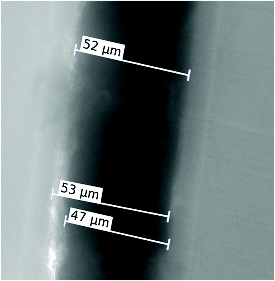 | ||
| Fig. 1 Optical microscope image of the graphene oxide foil cut. | ||
The GO foils were irradiated with 2.5 MeV H+ and 5.1 MeV He2+ ions in the implantation chamber installed at the 3 MV Tandetron MC 4130 accelerator. The ion irradiation fluencies used were 1.0 × 1013 cm−2, 1.0 × 1014 cm−2 and 1.0 × 1015 cm−2 for both types of ions. The ion irradiation was provided using an ion current density of 7.5–15.4 nA cm−2 in a vacuum of about 6.9 × 10⁻⁶ mbar.
Compositional study using RBS and ERDA
Rutherford Backscattering Spectrometry (RBS) and Elastic Recoil Detection Analysis (ERDA) were employed for the compositional study of GO foil before and after ion irradiation. The RBS spectra were measured using a beam of 2.0 MeV He+ ions. An Ultra-Ortec PIPS detector recorded He+ ions backscattered at a laboratory scattering angle of 170°. The ERDA spectra were measured using 2.5 MeV He+ ions. The primary beam was incident at an angle of 75° with respect to the foil surface normal, and hydrogen atoms that recoiled at a scattering angle of 30° were registered using a detector covered by a 12 μm Mylar foil. The typical ion current used during RBS and ERDA analysis was 5 nA. To reduce the effects of sample degradation during RBS/ERDA analysis, several particular spectra were measured on different beam spots and the final spectrum was obtained by summing the individual spectra. RBS and ERDA spectra were evaluated using the SIMNRA code.29 RBS and ERDA give us information about the compositional changes in the surface layer, where mostly electronic stopping takes place, and electronic stopping is a prevailing phenomenon in energy loss (see also Fig. 2, where SRIM simulation of the investigated ion penetration through GO foil is presented). Simultaneously, the precise prediction of the ion energy transfer into the graphene oxide foils can be realized only in the case of known chemical composition and density before ion irradiation.26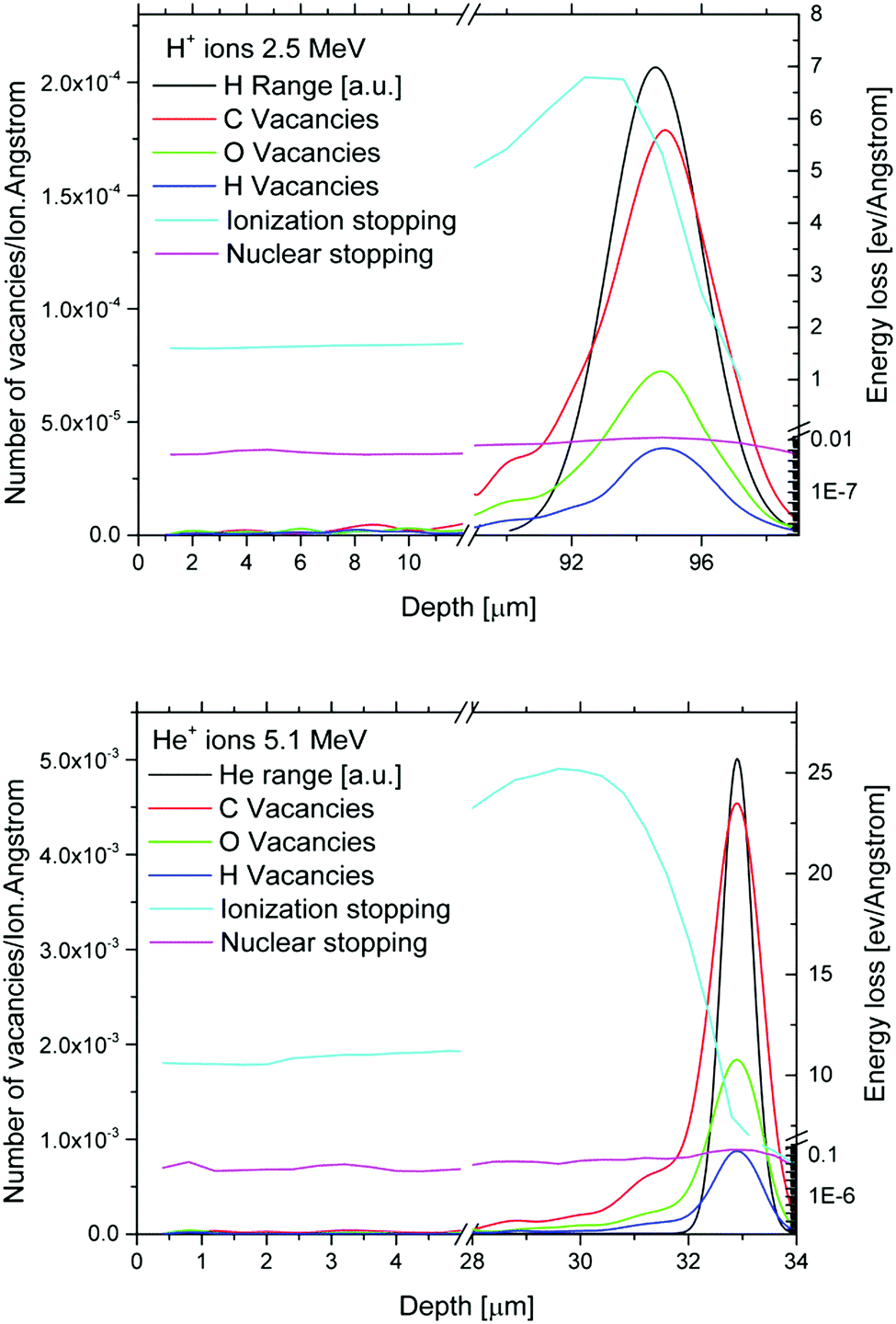 | ||
| Fig. 2 SRIM simulation of the electronic and nuclear energy stopping and vacancies in GO created by ion irradiation are presented for 2.5 MeV H+ (up) and 5.1 MeV He+ ions (down) simultaneously with H+ and He+ ion depth distribution. | ||
GO surface morphology determined by AFM measurements
The surface morphology changes were followed as they can provide information about the structural changes of the surface of the irradiated material and can be discussed in the frame of elemental and structural changes after ion irradiation.AFM morphological study and conductive AFM (C-AFM) of graphene foils were done before and after irradiation. The surface morphology, roughness and I–V characteristics were examined by Atomic Force Microscopy (AFM). The AFM NTEGRA Spectra from NT-MDT were measured in a tapping mode. The average roughness (Ra) and the root mean square (RMS) of the profile height deviations from the centre plane were calculated. The I–V characteristics were measured in the voltage range of −4 V to +4 V.
Optical and electrical properties of the irradiated GO foils
The changes of the electrical properties are related to structural changes in the irradiated GO foils. The electronic structure modification and bond rearrangement are prevailingly connected to the electronic stopping of energetic light ions in matter which prevails in the ion energy range used. These electronic structure modifications can significantly change the electrical properties of irradiated foils. Focused energetic ion beams can be used for micro-patterning of polymers, which is highly desirable in the case of graphene based structures to create microstructures with modified electrical resistivity. Thus, the study of electric resistivity of the irradiated GO foil is an important issue. In the same way, optical properties are closely connected to structural changes and electrical properties, and thus we also carried out an analysis of the optical properties of the ion irradiated GO foils in this work.The current–voltage (I–V) characteristics of pristine and irradiated GO foils were studied by the standard 2-point method utilizing a Keithley 6221 current source and a Keithley 2128A nano-voltmeter. The Ag contacts (50 nm thick) were sputtered on the surface of GO foils for electrical resistance measurements.
The optical properties of virgin and implanted GO foils were measured in a reflection mode, to cover the UV, visible and near-IR regions of the spectrum, using an AvaSpec-2048 spectrophotometer with UB-600 lines/mm grating and a bandwidth from 195 nm to 757 nm. A dual light source from the Avantes line of instruments, consisting of halogen/deuterium lamps, was employed in the range of 175–2500 nm and angle of incidence at 15°. The light impinged on the sample at an incidence angle of −15° with respect to the normal to the target plane and the optical spectrometer detected at +15°.
Structural and composition modification of GO foils determined using XPS, FTIR and Raman spectroscopy
Raman spectroscopy, ATR-FTIR and XPS measurements were used to get information about the structural and elemental modification of the surface of GO foils caused by energetic ion irradiation. Raman spectroscopy is considered as a powerful method to study carbon based materials due to the specific response to changes in the carbon hybridization state and introduction of defects.30 FTIR spectroscopy is nowadays considered as one of the most important tools to characterise chemical bonding within the carbon film since the involved groups and formed covalent bonds have characteristic absorption bands in the infrared spectra.31 XPS offers information about the chemical bonds and elemental composition in the very shallow subsurface region of the investigated graphene oxide foil under the ion beam.An inVia Raman microscope (Renishaw, England) was used for Raman spectroscopy measurements. The spectrometer operates in backscattering geometry with a CCD detector. An Nd-YAG laser (532 nm, 50 mW) with a 50× magnification objective was used for measurements. Instrument calibration was achieved with a silicon reference which yields a peak position at 520 cm−1. To avoid sample damage, no more than 5% of the total 50 mW laser power was used. Samples were drop-cast on a silicon wafer from an isopropanol suspension (1 mg mL−1) in order to perform the measurements.
Attenuated total reflectance Fourier transform infrared spectroscopy (ATR-FTIR) measurements were performed on a NICOLET iS50R FTIR spectrometer (Thermo Scientific, USA). A Diamond ATR crystal and a DTGS detector were used for all measurements, which were carried out in the range of 4000–400 cm−1 at a resolution of 4 cm−1.
High resolution X-ray photoelectron spectroscopy (XPS) was performed with an ESCAProbeP (Omicron Nanotechnology Ltd, Germany) spectrometer using a monochromatic aluminium X-ray radiation source (1486.7 eV). A wide-scan survey of all elements was performed, with subsequent high-resolution scans of the C 1s and O 1s core level spectra. For the evaluation of the carbon-to-oxygen (C/O) ratios from the survey spectra, relative sensitivity factors were used. Prior to measurement, samples were applied onto conductive carbon tape. To eliminate sample charging during measurement (1–5 V) an electron gun was used and the acquisition time of all XPS measurements was reduced to minimize the possibility of surface damage by X-rays.32
Results
Simulations of the structural changes after ion irradiation
For the initial estimation of the defect evolution caused by H+ and He2+ ion irradiation in the graphene oxide foils, the SRIM code33 was employed. When a beam of charged particles penetrates matter, ion deceleration is accompanied by electronic and nuclear stopping. The interplay of these two phenomena is crucial for structural changes of irradiated substrates. Electronic stopping (the prevailing phenomenon in our case) generally leads to atom ionisation, electron excitation and subsequent creation of free radicals and free chemical bonds. Nuclear stopping leads to atom knocking and production of vacancies.33 The SRIM package simulates the depth profiles of irradiation induced vacancy–interstitial Frenkel pairs (FP) using the binary collision approximation method and is unable to include the charge state fluctuation of projectile ions. In Fig. 2 we can see the depth profiles of the oxygen, hydrogen and carbon created vacancies in GO foil (using the full cascade MC simulation by SRIM) for He+ and H+ ions based on the chemical composition obtained from RBS. Simultaneously, the ion projected ranges realized at the above mentioned ion irradiation parameters are presented.In our case, the ratio of electronic stopping to nuclear stopping (Se/Sn) was 1720 for H+ ions with energy 2.5 MeV and 1500 for He+ ions with energy 5.1 MeV. The simulated projected range for H+ ions was 94.5 μm and for He+ ions 32.9 μm. It is evident that almost all H+ ions passed through the irradiated GO foil and that the He2+ ions are stopped deep inside the graphene oxide. The analytical techniques used were performed in such a way that they characterized the surface layer influenced exceptionally by ion electronic losses which is the focus of our research. The sum of SRIM predicted C, H and O vacancies created in the investigated GO foil by 5.1 MeV He+ ions is 5.9 times higher compared to the sum of all vacancies created by 2.5 MeV H+ ions.
Compositional study using RBS and ERDA
The elemental compositions of GO foil before and after ion irradiation for all used ion fluencies evaluated using RBS and ERDA are presented in Table 1. The accessible information depth in the case of graphene oxide and 2 MeV He+ ions, used as a probe in RBS analysis, is about 1 μm. Except for the presumed majority elements – carbon, hydrogen and oxygen, additional elements such as sulphur and manganese are also present in the analysed GO foils which originate from the synthesis procedure used for the preparation of GO foils. Hydrogen is generally present in graphene oxide in the form of hydroxyl functional groups, in which the hydrogen/oxygen (H/O) ratio typically reaches a value of 1, and the ratio H/O of about 0.5 is ascribed to carboxylic acids and 0 for ketones and epoxides.27 In our case the hydrogen/oxygen ratio is in the range of 0.38–0.48, and thus we can conclude the presence of carboxylic groups. The highest H/O ratio (0.48) was observed for pristine GO foil and this ratio decreases after ion irradiation, and thus the reduction of hydroxyl and carboxyl functional groups is suggested, which is further confirmed by XPS and ATR-FTIR analysis. It is obvious from Table 1 that after ion irradiation the elemental composition of GO foils, analysed using RBS and ERDA methods, exhibits only small changes as the electronic stopping prevailingly modified the structure and no significant escape of elements is observable because nuclear stopping is significantly less for both ions used as was predicted by SRIM simulation (see Fig. 2). Negligible elemental changes were expected, as the high energy light ions prevailingly modify the electronic structure of the irradiated material, which in consequence is exhibited in optical and electrical property modification.| Sample/ions | Composition of the deposited foils [at%] | ||||
|---|---|---|---|---|---|
| C | O | H | C/O | H/O | |
| Pristine GO foil | 63.5 ± 1.6 | 23.7 ± 0.5 | 11.4 ± 0.6 | 2.68 | 0.48 |
| 5.1 MeV He2+ 1.0 × 1013 cm−2 | 64.5 ± 1.6 | 23.7 ± 0.5 | 10.0 ± 0.5 | 2.72 | 0.42 |
| 5.1 MeV He2+ 1.0 × 1014 cm−2 | 64.2 ± 1.6 | 24.5 ± 0.6 | 10.3 ± 0.5 | 2.62 | 0.42 |
| 5.1 MeV He2+ 1.0 × 1015 cm−2 | 64.0 ± 1.6 | 24.7 ± 0.6 | 10.1 ± 0.5 | 2.59 | 0.41 |
| 2.5 MeV H+ 1.0 × 1013 cm−2 | 65.3 ± 1.6 | 23.0 ± 0.5 | 10.3 ± 0.5 | 2.84 | 0.45 |
| 2.5 MeV H+ 1.0 × 1014 cm−2 | 63.7 ± 1.5 | 24.8 ± 0.6 | 10.2 ± 0.5 | 2.57 | 0.41 |
| 2.5 MeV H+ 1.0 × 1015 cm−2 | 65.7 ± 1.6 | 23.2 ± 0.5 | 9.0 ± 0.5 | 2.83 | 0.38 |
GO surface morphology determined by AFM measurements
The GO foil morphology was investigated using Atomic Force Microscopy (AFM) in the tapping mode. AFM images and the corresponding surface height profiles before and after ion irradiation are shown in Fig. 3. All samples showed a very rough and irregular surface with a maximal height of the profile on the order of μm. It can be seen that after ion irradiation, the height of grains decreases from 1.6 μm for pristine GO foil to 0.8 μm for irradiated GO foil with an ion irradiation fluence of 1.0 × 1015 cm−1. The narrowing of the valleys on the GO surface can also be observed with increasing ion fluence for both ion species used. The main roughness characteristics are summarized in Table 2. The average roughness (Ra) and root mean square (RMS) decrease with increasing ion fluence for 2.5 MeV H+ ions (see Table 2). In the case of He+ ion irradiated GO foils, no such dependence is observed. The similar phenomenon was observed in the literature, where GO surface roughness decline under laser beam irradiation was presented.34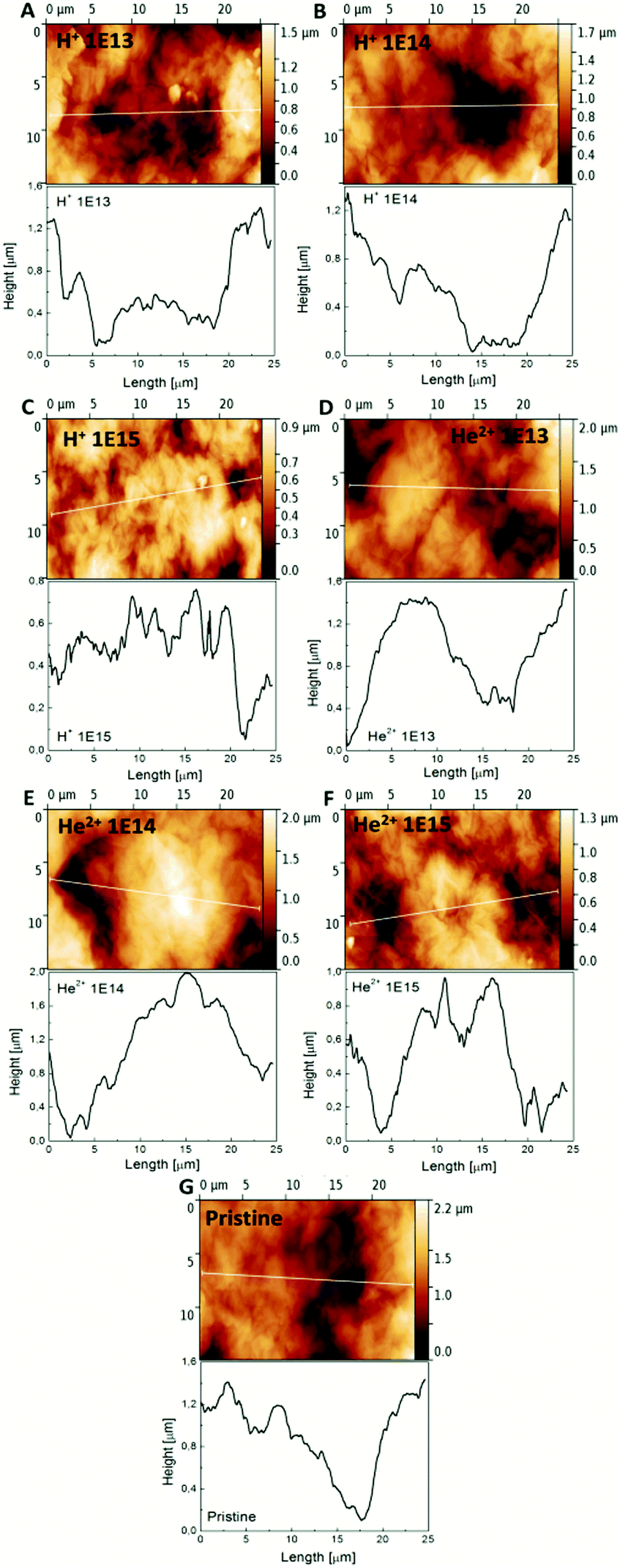 | ||
| Fig. 3 The AFM images of graphene oxide foils before and after ion irradiation: (A) GO foil irradiated using 2.5 MeV H+, 1.0 × 1013 cm−2, (B) GO foil irradiated using 2.5 MeV H+, 1.0 × 1014 cm−2, (C) GO foil irradiated using 2.5 MeV H+, 1.0 × 1015 cm−2, (D) GO foil irradiated using 5.1 MeV He2+, 1.0 × 1013 cm−2, (E) GO foil irradiated using 5.1 MeV He2+, 1.0 × 1014 cm−2, (F) GO foil irradiated using 5.1 MeV He2+, 1.0 × 1015 cm−2 and (G) pristine GO foil. | ||
| Sample | R a [nm] | RMS [nm] |
|---|---|---|
| Pristine GO foil | 290 | 357 |
| 2.5 MeV H+ 1.0 × 1013 cm−2 | 242 | 292 |
| 2.5 MeV H+ 1.0 × 1014 cm−2 | 236 | 297 |
| 2.5 MeV H+ 1.0 × 1015 cm−2 | 122 | 150 |
| 5.1 MeV He2+ 1.0 × 1013 cm−2 | 284 | 345 |
| 5.1 MeV He2+ 1.0 × 1014 cm−2 | 358 | 432 |
| 5.1 MeV He2+ 1.0 × 1015 cm−2 | 194 | 233 |
Structural and composition modification of GO foils determined using XPS, FTIR and Raman spectroscopy
The elemental species and chemical states in the surface of the GO foils before and after ion beam irradiation were investigated by means of X-ray Photoelectron Spectroscopy (XPS). This technique usually provides information about the sample surface, revealing details within several nanometres. The quantification of the C 1s and O 1s peaks and the ratio of C/O obtained from XPS spectra are summarized in Table 3. The carbon concentration and the C/O ratio are significantly enhanced for the ion fluence 1.0 × 1015 cm−2 for both ion species. Even though the increase in the C/O ratio is low, it is shown further in this work that this enhancement is sufficient in order to significantly increase the conductivity of the GO foil as discussed later on. RBS analysis shows the slight decline of the C/O ratio, but it must be emphasized that XPS provides information only about the close subsurface layer about several nm while RBS is able to evaluate the elemental composition averaged over the thick layers according to the penetration depth of the ion probe beam, e.g. about several micrometres. It can be assumed that the XPS observed C/O ratio is higher for the fluence 1.0 × 1015 cm−2 compared to RBS analysis due to the slightly higher surface decomposition of oxygen functionalities, as was observed after other type of ionizing irradiation – laser irradiation.34,35| Sample | C 1s (at%) | O 1s (at%) | C/O ratio |
|---|---|---|---|
| Pristine GO foil | 71.8 | 28.2 | 2.55 |
| 2.5 MeV H+ 1.0 × 1013 cm−2 | 68.9 | 31.1 | 2.15 |
| 2.5 MeV H+ 1.0 × 1014 cm−2 | 70.3 | 29.7 | 2.37 |
| 2.5 MeV H+ 1.0 × 1015 cm−2 | 75.2 | 24.8 | 3.03 |
| 5.1 MeV He2+ 1.0 × 1013 cm−2 | 70.7 | 29.3 | 2.41 |
| 5.1 MeV He2+ 1.0 × 1014 cm−2 | 71.0 | 29.0 | 2.45 |
| 5.1 MeV He2+ 1.0 × 1015 cm−2 | 78.5 | 21.5 | 3.65 |
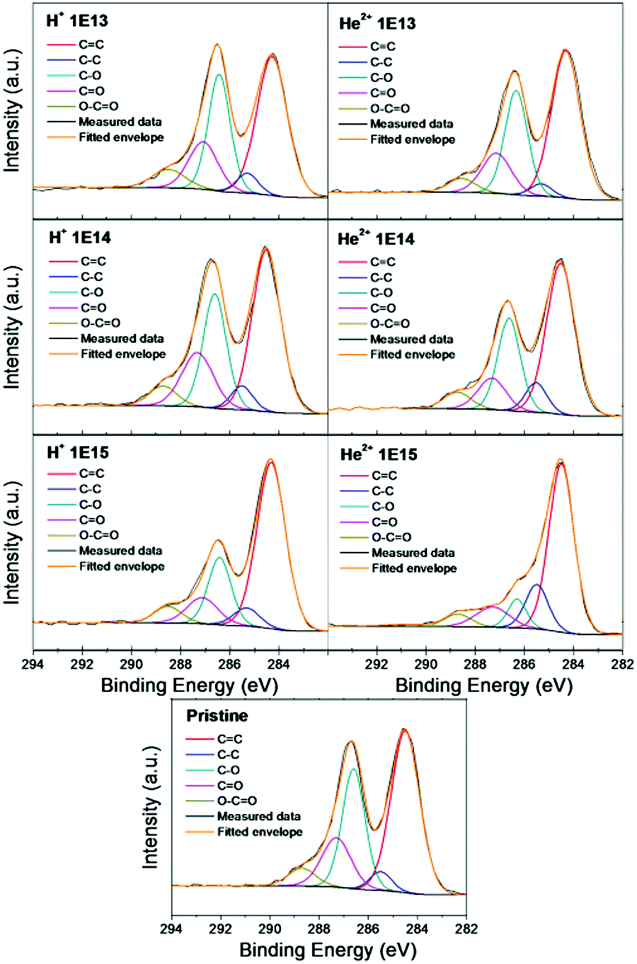
The deconvolution of the high resolution XPS spectra of the C 1s peak of pristine and irradiated GO foils is shown in Fig. 4 and Table 4. In this figure, one can indicate the presence of five different carbon bonding states; C![[double bond, length as m-dash]](https://www.rsc.org/images/entities/char_e001.gif) C (284.4), C–C (285.4), C–O (286.3), CO (288.0) and O–CO (289.0). Among these bonding states, CC and C–O dominated in pristine GO foil and indicate the considerable degree of oxidation.36 After ion irradiation, a decrease of peak intensity is observed, attributed to the oxygen functionalized carbon and increasing intensity of the CC and C–C peaks. Although all five indicated carbon chemical states are present for all the GO foils, the concentration of individual chemical states varies. The CC peak gradually becomes more dominant for GO foils irradiated using higher ion fluence, reaching a maximum for GO foil irradiated using 5.1 MeV He+ ions, 1.0 × 1015 cm−2. This phenomenon demonstrates the removal of the oxygen containing groups and creation of the carbon groups with increasing ion fluence. Similar results were observed when GO was irradiated using 100 MeV Au ions in ref. 36 and using Ti ions with different energies.37
C (284.4), C–C (285.4), C–O (286.3), CO (288.0) and O–CO (289.0). Among these bonding states, CC and C–O dominated in pristine GO foil and indicate the considerable degree of oxidation.36 After ion irradiation, a decrease of peak intensity is observed, attributed to the oxygen functionalized carbon and increasing intensity of the CC and C–C peaks. Although all five indicated carbon chemical states are present for all the GO foils, the concentration of individual chemical states varies. The CC peak gradually becomes more dominant for GO foils irradiated using higher ion fluence, reaching a maximum for GO foil irradiated using 5.1 MeV He+ ions, 1.0 × 1015 cm−2. This phenomenon demonstrates the removal of the oxygen containing groups and creation of the carbon groups with increasing ion fluence. Similar results were observed when GO was irradiated using 100 MeV Au ions in ref. 36 and using Ti ions with different energies.37
 | ||
| Fig. 4 The deconvolution of the XPS C 1s peak of pristine GO foil and GO foils irradiated using 2.5 MeV H+ and 5.1 MeV He2+ ions using various ion fluencies. | ||
| Sample | CC |
C–C | C–O | CO |
O–CO |
|---|---|---|---|---|---|
| Pristine GO foil | 47.5 ± 1.1 | 4.2 ± 0.1 | 28.2 ± 0.6 | 15.0 ± 0.3 | 5.1 ± 0.1 |
| 2.5 MeV H+ 1.0 × 1013 cm−2 | 45.8 ± 1.1 | 4.7 ± 0.1 | 27.8 ± 0.6 | 15.0 ± 0.3 | 6.7 ± 0.2 |
| 2.5 MeV H+ 1.0 × 1014 cm−2 | 46.1 ± 1.1 | 5.2 ± 0.1 | 26.4 ± 0.6 | 17.0 ± 0.4 | 5.3 ± 0.1 |
| 2.5 MeV H+ 1.0 × 1015 cm−2 | 59.1 ± 1.4 | 5.9 ± 0.1 | 19.1 ± 0.4 | 10.2 ± 0.2 | 5.7 ± 0.1 |
| 5.1 MeV He2+ 1.0 × 1013 cm−2 | 50.3 ± 1.2 | 3.1 ± 0.1 | 28.0 ± 0.6 | 14.0 ± 0.3 | 4.6 ± 0.1 |
| 5.1 MeV He2+ 1.0 × 1014 cm−2 | 51.5 ± 1.2 | 7.6 ± 0.2 | 24.9 ± 0.6 | 10.5 ± 1.3 | 5.5 ± 0.1 |
| 5.1 MeV He2+ 1.0 × 1015 cm−2 | 62.2 ± 1.4 | 15.0 ± 0.3 | 7.8 ± 0.2 | 10.1 ± 0.2 | 4.9 ± 0.1 |
The ATR-FTIR spectra of the pristine and irradiated GO foils recorded in the wavenumber range of 4000–400 cm−1 are presented in Fig. 5. The pristine GO shows characteristic bands that confirm the presence of functional groups, such as O–H, CO, C–OH, and C–O. The broad characteristic peak between 3000 and 3600 cm−1 represents the O–H stretching of hydroxyl and carboxyl groups which is significantly reduced with increasing ion irradiation fluence for He2+ and H+ ions.38,39 The oxygen in the pristine sample can be confirmed mainly by the absorption bands at ∼1730 cm−1 (CO stretching vibration) and by the presence of a broad band at 1000–1200 cm−1 attributed to C–O alkoxy and epoxy stretching vibration.36,40,41 The presence of the absorption peak at ∼1630 cm−1 can be attributed to the stretching vibration of CC of the graphene skeleton.38 The presence of hydroxyl groups results in the formation of hydrogen bonds which contribute to the hydrophilic nature of graphene oxide. Fig. 5 shows that with increasing ion irradiation fluence, the intensity of all the peaks ascribed to the oxygen chemical states decrease and this decrease is more pronounced for GO samples irradiated using He2+ ions. The ATR-FTIR spectra indicated the chemical reduction of GO foil after ion irradiation due to the electronic energy transferred from H+ and He2+ ions to the GO system and the GO reduction is more pronounced for He2+ ions as predicted by SRIM simulation as the ionization of GO is to a larger extent realized by He+ ions compared to H+ ions. The chemical reduction of GO was accompanied by a decrease or even suppression of the intensity of different oxygen peaks as observed in FTIR spectra.36
 | ||
| Fig. 5 The ATR-FTIR spectra of pristine and irradiated GO foils. The ion beam irradiation was performed using 2.5 MeV H+ and 5.1 MeV He2+ ions with different fluencies. | ||
To get more comprehensive insight into graphene oxide reduction under the light energetic ion irradiation, Raman spectroscopy was used. In all Raman spectra, two major peaks, corresponding to the D (1350 cm−1) and G (1590 cm−1) bands, were observed (see Fig. 6). The D band is assigned to defect induced Raman features, and this band cannot be seen for highly crystalline graphite/graphene samples.42 The G band peak is associated with the vibration of sp2 bonded carbon atoms in graphene.22,41,43 The double peak present around 2700 cm−1 is generally labelled as 2D band and indicates the reduction of GO.41 The intensity ratio ID/IG for the D band and G band is widely used for characterizing the defect quantity in pristine and irradiated GO foils. Defects as well as oxygen functionalities in graphene significantly influence its transport and electrocatalytic properties.42 The ID/IG ratio decreases with increasing ion fluence for the GO foils irradiated using 5.1 MeV He2+ ions (see Table 5). This suggests that irradiation with He2+ ions leads to the formation of more sp2 graphene domains and this can be ascribed to the reduction of graphene oxide.27,36 This is also in agreement with XPS and ATR-FTIR results, which revealed carbon–carbon bond creation and destruction of oxygen functionalities along with oxygen release from the GO foil surface.
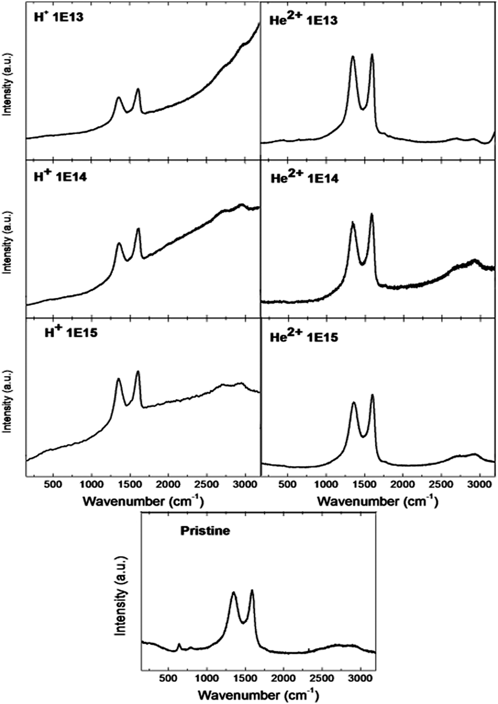 | ||
| Fig. 6 The Raman spectra of pristine and irradiated GO foils. The ion beam irradiation was performed using 2.5 MeV H+ and 5.1 MeV He+ ions with different ion irradiation fluencies. | ||
| Sample | I D/IG |
|---|---|
| Pristine graphene | 0.95 |
| 2.5 MeV H+ 1.0 × 1013 cm−2 | 0.91 |
| 2.5 MeV H+ 1.0 × 1014 cm−2 | 0.91 |
| 2.5 MeV H+ 1.0 × 1015 cm−2 | 1.08 |
| 5.1 MeV He2+ 1.0 × 1013 cm−2 | 0.98 |
| 5.1 MeV He2+ 1.0 × 1014 cm−2 | 0.90 |
| 5.1 MeV He2+ 1.0 × 1015 cm−2 | 0.89 |
Optical and electrical properties of the irradiated GO foils
UV-Vis spectroscopy (UV-Vis) was used for the characterization of the structural changes of GO foil after ion irradiation. GO foils irradiated with H+ and He2+ and also pristine foils were analysed by UV-Visible-IR spectroscopy over the range of fluencies from 1.0 × 1013 cm−2 to 1.0 × 1015 cm−2. Fig. 7A presents the normalized reflectivity curves for the virgin and the irradiated GO foils using a proton beam with 2.5 MeV of energy. One can see the overlapping curves of all the investigated GO foils due to the very slight surface layer modification by H+ ions. The reflectivity of GO foil irradiated by protons calculated in the visible wavelength region is about 2.1% for the pristine foil and ranges between 2.1 and 2.5% for the 2.5 MeV H+ irradiated GO foils. We didn't observe any significant influence of ion irradiation on UV-Vis reflectivity. | ||
| Fig. 7 (A) Optical spectra for both pristine and implanted GO foils using protons with an energy of 2.5 MeV and fluencies of 1013 cm−2, 1014 cm−2, and 1015 cm−2. (B) Optical spectra for both pristine and implanted graphite oxide foils using alpha particles with an energy of 5.1 MeV and fluencies of 1013 cm−2, 1014 cm−2, and 1015 cm−2. | ||
Fig. 7B shows the comparison between the reflectivity exhibited by the virgin and the ion irradiated GO foils using He2+ ions of 5.1 MeV. The graphene oxide foil irradiated using He2+ ions at a fluence of 1.0 × 1015 cm−2 shows an increase in reflectivity compared to the other pristine and irradiated samples. This irradiated GO sample exhibits a reflectivity of about 4.2% in the visible wavelength region (390–760 nm) that corresponds to the photon energy in the range from 1.6 to 3.4 eV. This reflectivity enhancement can be connected to the band gap decline in the irradiated GO foil.
To investigate the change of electrical properties after ion irradiation, the current–voltage (I–V) characteristics were measured using the standard two point method in the current range from −1000 nA to 1000 nA (see Fig. 8). All pristine and irradiated GO foils exhibited a clear non-linear slope of the I–V characteristic curve. After ion irradiation using an ion fluence of 1.0 × 1015 cm−2, the GO foils showed a remarkable enhancement in current response compared to the pristine GO foil, for both ion species used. The electrical resistivity decrease is more pronounced for GO foil irradiated using 5.1 MeV He+ ions. These changes of the electrical resistivity after ion irradiation are in accordance with the creation of sp2 domains confirmed by Raman spectroscopy and the decrease of the oxygen concentration observed by XPS and RBS, simultaneously with the destruction of oxygen functional groups in the surface of irradiated GO foils as observed by FTIR analysis. A conductive network in GO with many cross-linked carbon connections facilitates ion energy transfer to the graphene oxide structure via electronic stopping.36
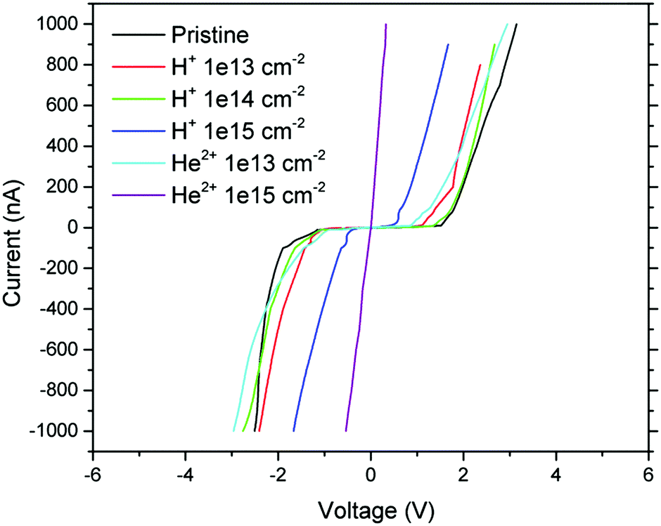 | ||
| Fig. 8 The I–V characteristics of pristine and irradiated GO foils obtained using the standard two point method. The ion beam irradiation was performed using 2.5 MeV H+ and 5.1 MeV He2+ ions with different fluencies. | ||
Fig. 9 shows the cyclic V–A graphs of pristine and irradiated GO foils measured by means of conductive AFM analysis (C-AFM). The voltage range during C-AFM analysis was in the range of −4 V to +4 V. One can see clear non-linear characteristics and hysteresis around zero. The capacitive behaviour is decreasing with increasing ion fluence for both ion species used. This phenomenon can be connected to the created electrochemical active sites caused by deoxygenation and leads to the improvement in electrical conductivity.36
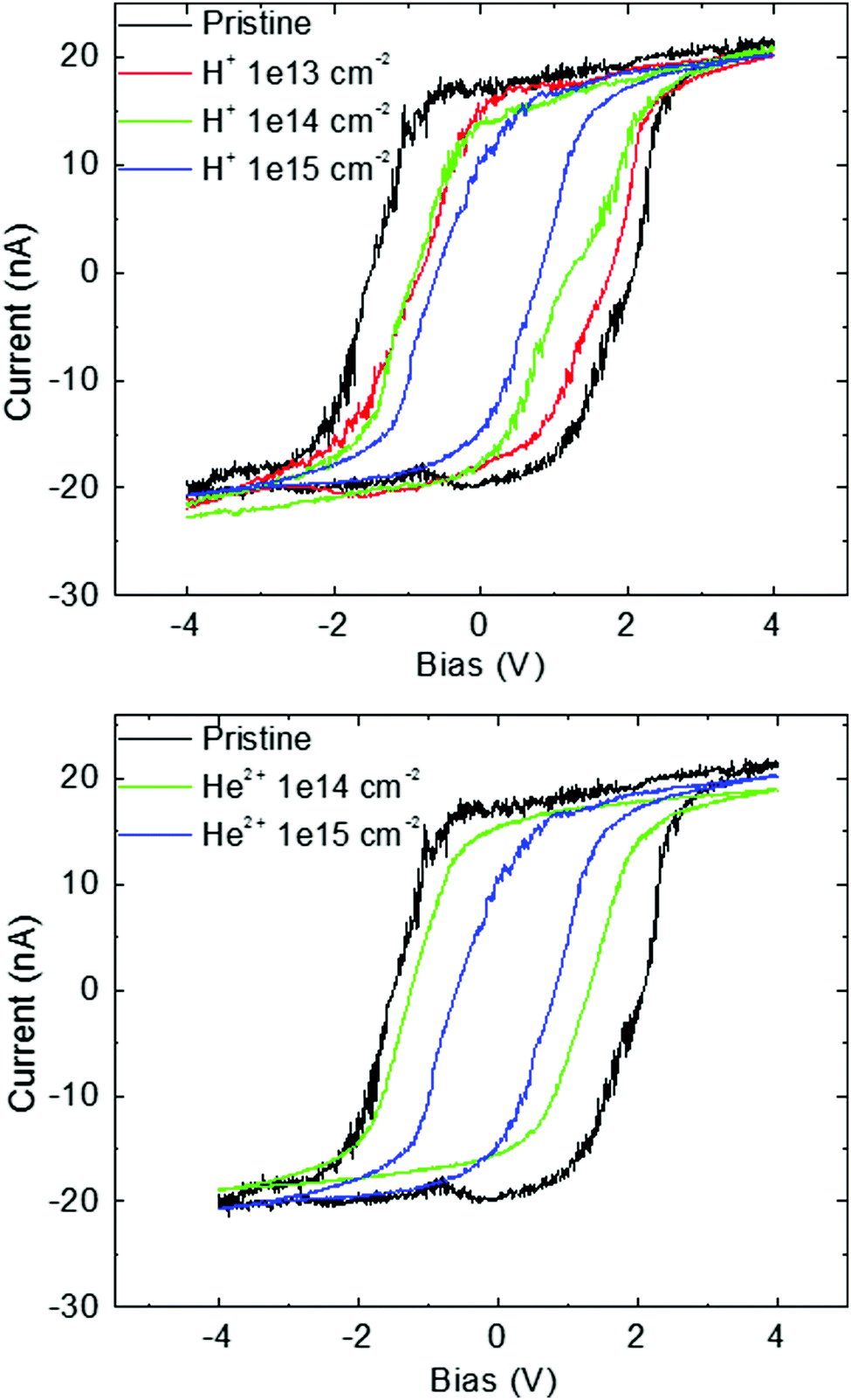 | ||
| Fig. 9 The I–V characteristics of pristine and irradiated GO foils obtained using C-AFM. The ion beam irradiation was performed using 2.5 MeV H+ and 5.1 MeV He2+ ions with different fluencies. | ||
Discussion
Graphene is reported as a material with high electric conductivity, whereas graphene oxide is an electrical insulator and its reduction and deoxygenation can modify the electrical properties in such a way that GO can become a semiconductor or a conductor.37,44 In our experiments, the GO foils irradiated by hydrogen and helium ions using the fluence 1.0 × 1015 cm−2 exhibit much better conductivity compared to the pristine GO foil, and this tendency is more pronounced for the He2+ ions. This is in accordance with the results obtained by FTIR, XPS and Raman spectroscopy, which give us information that light ion irradiation of GO foils leads to a reduction of oxygen functionalities. Raman spectroscopy results suggest the formation of graphene sp2 domains after irradiation using He2+ ions. FTIR and XPS demonstrated that ion irradiation destroyed the surface oxygen chemical bonds (CO and C–O), and led to the formation of CC and C–C bonds, whereas the significant oxygen release was not observed by RBS in deeper layers of GO samples. These changes of the chemical bonds, deoxygenation and carbonization of the GO surface, connected with an increase in conductivity, are caused by transfer of electronic energy during ion irradiation.31 The SRIM simulation shows that electronic stopping prevailing in the surface layer is higher for the He+ ions compared to H+ ones, which resulted in the more pronounced influence during irradiation using the He2+ ions. This is owing to the four times bigger mass of He compared to the H. Moreover, the penetration of charged ions can enhance the electronic stopping in the target material.31
Conclusions
The graphene oxide foils were irradiated using 2.5 MeV H+ and 5.1 MeV He2+ ions with ion fluencies in the range of 1.0 × 10¹³–1.0 × 1015 cm−2. C, O, and H contents in the bulk of pristine and irradiated GO foil obtained from RBS and ERDA analysis are similar for all samples, and thus, there seems to be no correlation between the ion irradiation fluence and the content of those elements. However, this is not surprising if we consider the highly prevalent electron stopping compared to the nuclear ones for the ion species used and their energy. On the other hand, the results of XPS, Raman and ATR-FTIR surface analysis revealed significant changes after ion irradiation. The Raman spectra and FTIR analysis showed the formation of sp2 bonded carbon atoms and growth of the graphene domains and reduction of the GO foil surface. From XPS and FTIR results it can be concluded that the electronic structure and chemical bonds in the irradiated GO foil surface are directly connected to the ion species and their fluence. In addition, the higher ion fluence caused the roughness decline and self-evident electrical resistivity decrease of the ion irradiated GO foils. The presented study shows that irradiation using light energetic ions is one of the methods for modification of graphene oxide that can change its optical and electrical properties.Acknowledgements
The research has been carried out at the CANAM (Center of Accelerators and Nuclear Analytical Methods) infrastructure (LM2015056) and has been supported by Czech Science Foundation (GACR No. 16-05167S). Z. S., J. L. and D. B. were supported by specific university research (MSMT No. 20-SVV/2017).Notes and references
- D. R. Dreyer, S. Park, Ch. W. Bielawski and R. S. Ruoff, Chem. Soc. Rev., 2010, 39, 228–240 RSC.
- Y. P. Tang, D. R. Paul and T. S. Chung, J. Membr. Sci., 2014, 458, 199–208 CrossRef CAS.
- V. Mazánek, O. Jankovský, J. Luxa, D. Sedmidubský, Z. Janoušek, F. Šembera and Z. Sofer, Nanoscale, 2015, 7, 13646–13655 RSC.
- G. Liu, W. Jin and N. Xu, Chem. Soc. Rev., 2015, 44, 5016–5030 RSC.
- Q. Xu, H. Xu, J. Chen, Y. Lv, Ch. Dong and T. S. Sreeprasad, Inorg. Chem. Front., 2015, 2, 417–424 RSC.
- Ch. Chi, X. Wang, Y. Peng, Y. Qian, Z. Hu, J. Dong and D. Zhao, Chem. Mater., 2016, 28, 2921–2927 CrossRef CAS.
- D. Jariwala, V. K. Sangwan, L. J. Lauhon, T. J. Marks and M. C. Hersam, Chem. Soc. Rev., 2013, 42, 2824–2860 RSC.
- D. R. Dreyer, S. Park, Ch. W. Bielawski and R. S. Ruoff, Chem. Soc. Rev., 2010, 39, 228–240 RSC.
- R. K. Joshi, S. Alwarappan, M. Yoshimura, V. Shajwala and Y. Nishima, Appl. Mater. Today, 2015, 1, 1–12 CrossRef.
- Ch. K. Chua and M. Pumera, Chem. Soc. Rev., 2014, 43, 291–312 RSC.
- Y. Zhu, S. Murali, W. Cai, X. Li, J. W. Suk, J. R. Potts and R. S. Ruoff, Adv. Mater., 2010, 22, 3906–3924 CrossRef CAS PubMed.
- M. Pumera, Electrochem. Commun., 2013, 36, 14–18 CrossRef CAS.
- G. Buchowicz, P. R. Stone, J. T. Robinson, C. D. Cress, J. W. Beeman and O. D. Dubon, Appl. Phys. Lett., 2011, 98, 032102 CrossRef.
- J. H. Chen, W. G. Cullen, C. Jang, M. S. Fuhrer and E. D. Williams, Phys. Rev. Lett., 2015, 102, 236805 CrossRef PubMed.
- B. D. Guo, Q. A. Liu, E. D. Chen, H. W. Zhu, L. A. Fang and J. R. Gong, Nano Lett., 2010, 10, 4975 CrossRef CAS PubMed.
- M. C. Lemme, D. C. Bell, J. R. Williams, L. A. Stern, B. W. H. Baugher, P. Jarillo-Herrero and C. M. Marcus, ACS Nano, 2009, 3, 2674 CrossRef CAS PubMed.
- M. Kalbac, O. Lehtinen, A. V. Krasheninnikov and J. Keinonen, Adv. Mater., 2015, 25, 1004–1009 CrossRef PubMed.
- D. J. McComas, F. Allegrini, C. J. Pollock, H. O. Funsten, S. Ritzau and G. Gloeckler, Rev. Sci. Instrum., 2004, 75, 4863–4870 CrossRef CAS.
- M. Y. Han, B. Ozyilmaz, Y. Zhang and P. Kim, Phys. Rev. Lett., 2007, 98, 206805 CrossRef PubMed.
- H. O. Funsten, F. Allegrini, P. Bochsler, G. Dunn, S. Ellis, D. Everett, M. J. Fagan, S. A. Fuselier, M. Granoff and M. Gruntman, et al. , Space Sci. Rev., 2009, 146, 75–103 CrossRef.
- M. Gruntman, Rev. Sci. Instrum., 1997, 68, 3617–3656 CrossRef CAS.
- D. Hovestadt, M. Hilchenbach, A. Bürgi, B. Klecker, P. Laeverenz, M. Scholer, H. Grünwaldt, W. I. Axford and S. Livi, et al. , Sol. Phys., 1995, 162, 441–481 CrossRef CAS.
- Y. Zhang, L. Guo, S. Wei, Y. He, H. Xia, Q. Chen, H. B. Sun and F. S. Xiao, Nano Today, 2010, 5, 15–20 CrossRef CAS.
- A. H. Castro Neto, F. Guinea, N. M. R. Peres, K. S. Novoselov and A. K. Geim, Rev. Mod. Phys., 2009, 81, 109 CrossRef CAS.
- V. M. Pereira, F. Guinea, J. M. B. Lopes dos Santos, N. M. R. Peresand and A. H. Castro Neto, Phys. Rev. Lett., 2006, 96, 036801 CrossRef PubMed.
- R. Mikšová, A. Macková, P. Malinský and Z. Sofer, The stopping power and energy straggling of light ions in graphene oxide films, will be published.
- O. Jankovský, P. Šimek, J. Luxa, D. Sedmidubský, I. Tomandl, A. Macková, R. Mikšová, P. Malinský, M. Pumera and Z. Sofer, ChemPlusChem, 2015, 80, 1399–1407 CrossRef.
- Ch. K. Chua and M. Pumera, Small, 2015, 11, 1266–1272 CrossRef CAS PubMed.
- M. Mayer, SIMNRA version 6.06, Max-Planck-Institut fur Plasmaphysik Garching, Germany, 2006, available at: http://www.rzg.mpg.de/˜mam/ Search PubMed.
- G. Compagnini, F. Giannazzo, S. Sonde, V. Raineri and E. Rimini, Carbon, 2009, 47, 3201–3207 CrossRef CAS.
- V. Georgakilas, Functionalization of Graphene, John Wiley & Sons, Germany, 2014, ISBN 352733551X Search PubMed.
- Ch. K. Chua, A. Ambrosi and M. Pumera, Analyst, 2013, 138, 7012–7015 RSC.
- J. F. Ziegler, et al., SRIM: The Stopping and Range of Ions in Matter, Version SRIM-2013, available at: http://www.srim.org/ Search PubMed.
- I. I. Bobrinetskiy, A. V. Emelianov, S. A. Smagulova, I. A. Komarov, N. Otero and P. M. Romero, Mater. Lett., 2017, 187, 20–23 CrossRef CAS.
- P. Kumar, K. S. Subrahmanyan and C. N. R. Rao, Int. J. Nanosci., 2011, 10, 559 CrossRef CAS.
- K. Hareesh, R. P. Joshi, B. Shateesh, K. Asokan, D. Kanjilal, D. J. Late, S. S. Dahiwale, V. N. Bhoraskar, S. K. Haram and S. D. Dhole, J. Phys. D: Appl. Phys., 2015, 48, 365105 CrossRef.
- J. Chen, G. Zhang, B. Luo, D. Sun, X. Yan and Q. Xue, Carbon, 2011, 49, 3141–3147 CrossRef CAS.
- N. Cao and Y. Zhang, J. Nanomater., 2015, 2015, 16812 Search PubMed.
- L. Shahriary and A. A. Athawale, Int. J. Renew. Energy Environ. Eng., 2014, 2, 58–63 Search PubMed.
- O. Jankovský, P. Šimek, K. Klimová, D. Sedmidubský, S. Matějková, M. Pumera and Z. Sofer, Nanoscale, 2014, 6, 6065 RSC.
- M. M. Viana, M. C. F. S. Lima, J. C. Forsythe, V. S. Gangoli, M. Cho, Y. Cheng, G. G. Silva, M. S. Wong and V. Caliman, J. Braz. Chem. Soc., 2015, 26, 978–984 CAS.
- M. A. Pimenta, G. Dresselhaus, M. S. Dresselhaus, L. G. Cançado, A. Jorio and R. Saito, Phys. Chem. Chem. Phys., 2007, 9, 1276–1291 RSC.
- E. D. Dikio, F. T. Thema, A. M. Farah and N. D. Shoto, Mater. Sci.-Pol., 2013, 31, 59–64 CrossRef CAS.
- S. Pei and H. M. Cheng, Carbon, 2012, 50, 3210–3228 CrossRef CAS.
| This journal is © the Owner Societies 2017 |