Assembly of 1D nanofibers into a 2D bi-layered composite nanofibrous film with different functionalities at the two layers via layer-by-layer electrospinning
Received
27th August 2016
, Accepted 12th November 2016
First published on 22nd November 2016
Abstract
A two-dimensional (2D) bi-layered composite nanofibrous film assembled by one-dimensional (1D) nanofibers with trifunctionality of electrical conduction, magnetism and photoluminescence has been successfully fabricated by layer-by-layer electrospinning. The composite film consists of a polyaniline (PANI)/Fe3O4 nanoparticle (NP)/polyacrylonitrile (PAN) tuned electrical–magnetic bifunctional layer on one side and a Tb(TTA)3(TPPO)2/polyvinylpyrrolidone (PVP) photoluminescent layer on the other side, and the two layers are tightly combined face-to-face together into the novel bi-layered composite film of trifunctionality. The brand-new film has totally different characteristics at the double layers. The electrical conductivity and magnetism of the electrical–magnetic bifunctional layer can be, respectively, tunable via modulating the PANI and Fe3O4 NP contents, and the highest electrical conductivity can reach up to the order of 10−2 S cm−1, and predominant intense green emission at 545 nm is obviously observed in the photoluminescent layer under the excitation of 357 nm single-wavelength ultraviolet light. More importantly, the luminescence intensity of the photoluminescent layer remains almost unaffected by the electrical–magnetic bifunctional layer because the photoluminescent materials have been successfully isolated from dark-colored PANI and Fe3O4 NPs. By comparing with the counterpart single-layered composite nanofibrous film, it is found that the bi-layered composite nanofibrous film has better performance. The novel bi-layered composite nanofibrous film with trifunctionality has potential in the fields of nanodevices, molecular electronics and biomedicine. Furthermore, the design conception and fabrication technique for the bi-layered multifunctional film provide a new and facile strategy towards other films of multifunctionality.
Introduction
Recently, one-dimensional (1D) nanomaterials, including nanotubes, nanobelts and nanofibers, have attracted increasing interest because of their unique structure,1 large surface area2 and novel properties.3 Meanwhile, it is frequently necessary to assemble 1D nanomaterials into macroscopic architectures such as two-dimensional (2D) films,4 for practical applications.5 In the last few years, multifunctional composite materials have attracted increased attention from scientists all over the world, for the reason that multifunctional materials are specifically developed to effectively reduce the system size. Multifunctional materials can be used in various fields including energy storage, biological films and absorption materials.6–8 Recently, investigation on the luminescent–electrical–magnetic bi- or tri-functional materials has become one of the hot subjects of study in the field of materials science.
Rare earth (RE) organic complexes have unique electronic, optical and chemical properties due to the f–f electron transition of the RE ions,9,10 and they have been extensively applied to luminescent devices, displays, biolabeling, optical imaging, and phototherapy,11–16etc. Fe3O4 nanoparticles (NPs) have been greatly focused on, owing to their excellent magnetism, biomedical applications,17 and low toxicity.18 Some types of magnetic-photoluminescent bifunctional nanomaterials have been reported, which have potential application in biological cell separation, magnetic resonance imaging (MRI), and drug/gene delivery.19–22 As a popular conducting polymer, polyaniline (PANI) has been widely explored and used in many areas such as electrochromic devices, secondary batteries, catalysts and electromagnetic interference (EMI) shielding materials owing to its light weight, low cost, tunable conductivity, and environmental stability.23,24 Recently, trifunctional Tb(BA)3phen/PANI/Fe3O4/PVP hollow nanofibers fabricated by the electrospinning process have been reported in the literature.25 In view of previous work by us and other researchers, as for luminescent–electrical–magnetic trifunctional materials, the luminescence intensity of the RE compounds will greatly decrease if the RE compounds directly contact with deep-colored materials like Fe2O3, Fe3O4 and PANI.26,27 Therefore, it is urgently required to find a new way of effectively isolating luminescent materials from Fe2O3, Fe3O4 and PANI.
Electrospinning is a relatively simple, straightforward and versatile fiber-forming technology,28,29 which provides a unique way to produce nanofibers from polymer solutions or melts.30 Moreover, electrospinning technology is a novel way to assemble 1D nanofibers or nanobelts into 2D films. During the electrospinning process, the nanofibers or nanobelts are forced to jet out from a small hole and are collected on a grounded metal flat.31,32 The 2D macroscopic nanofibrous film is formed as long as a sufficient amount of nanofibers or nanobelts accumulates. To date, some studies on electrospun bi-layered films have been reported. PVA/PCL bilayer nanofibrous scaffolds were developed for tissue engineering applications.33 Wu et al.34 fabricated a ‘water diode’ film containing a layer of hydrophobic polyurethane and another layer of hydrophilic cross-linked poly(vinyl alcohol), which realized the separation of oil and water. Inspired by these bi-layered films35 that have the advantages of easy multifunctionalization, low cost and easy manipulation, etc., in this work, we propose a layer-by-layer electrospinning technique to fabricate a novel bi-layered composite nanofibrous film. Of the novel film, one layer is formed by PVP nanofibers containing an RE complex that exhibits photoluminescence properties, and the other layer consists of nanofibers containing PANI, Fe3O4 NPs and PAN which have tunable electrical–magnetic bifunctionality. In order to illustrate the advantages of the bi-layered film, we also prepared the counterpart single-layered composite nanofibrous film with the same components as a contrast sample. The morphology, structure and properties of the samples were systematically studied and some new interesting results were obtained. Owing to its multifunctionality, the new type of bi-layered film will have promising applications in many fields such as electromagnetic interference shielding, nanodevices and drug delivery, etc.
Experimental sections
Chemicals
PVP K90 (Mw ≈ 90![[thin space (1/6-em)]](https://www.rsc.org/images/entities/char_2009.gif) 000), polyethylene glycol (PEG, Mw ≈ 20000), Tb4O7 (99.99%), FeCl3·6H2O, FeSO4·7H2O, NH4NO3, anhydrous ethanol, and N,N-dimethylformamide (DMF) were bought from Tianjin Tiantai Fine Chemical Co., Ltd. PAN, oleic acid (OA), aniline (ANI), and (IS)-(+)-camphor-10 sulfonic acid (CSA) were purchased from Sinopharm Chemical Reagent Co., Ltd. Triphenylphosphine oxide (TPPO) was bought from Saen Chemical Co., Ltd. 2-Thenoyltrifluoroacetone (HTTA) was purchased from Aladdin Chemistry Co., Ltd. Ammonium persulfate (APS) was bought from Guangdong Xilong Chemical Co., Ltd. Nitric acid (HNO3, AR) was purchased from Beijing Chemical Works. All the reagents were of analytical grade and were directly used as received without further purification. The deionized water was homemade.
000), polyethylene glycol (PEG, Mw ≈ 20000), Tb4O7 (99.99%), FeCl3·6H2O, FeSO4·7H2O, NH4NO3, anhydrous ethanol, and N,N-dimethylformamide (DMF) were bought from Tianjin Tiantai Fine Chemical Co., Ltd. PAN, oleic acid (OA), aniline (ANI), and (IS)-(+)-camphor-10 sulfonic acid (CSA) were purchased from Sinopharm Chemical Reagent Co., Ltd. Triphenylphosphine oxide (TPPO) was bought from Saen Chemical Co., Ltd. 2-Thenoyltrifluoroacetone (HTTA) was purchased from Aladdin Chemistry Co., Ltd. Ammonium persulfate (APS) was bought from Guangdong Xilong Chemical Co., Ltd. Nitric acid (HNO3, AR) was purchased from Beijing Chemical Works. All the reagents were of analytical grade and were directly used as received without further purification. The deionized water was homemade.
Preparation of oleic acid modified Fe3O4 NPs
In order to fabricate Fe3O4 NPs with particle sizes of 8–10 nm, a facile co-precipitation synthetic method was adopted, and PEG was used as the protective agent to prevent the particles from aggregation and simultaneously improve monodispersity, stability, and solubility. The synthetic procedure was as follows: 5.4060 g of FeCl3·6H2O, 2.7800 g of FeSO4·7H2O, 4.0400 g of NH4NO3 and 1.9 g of PEG were added to 100 mL of deionized water to form a uniform solution under vigorous stirring at 50 °C. At the same time, the reactive mixture was kept under an argon atmosphere to prevent the oxidation of Fe2+. After the mixture had been bubbled with argon for 30 min, 0.1 mol L−1 of NH3·H2O was added dropwise to the mixture to adjust the pH value above 11. Then the system was continuously bubbled with argon for 20 min at 50 °C, and black precipitates were formed. Per 1.0000 g of the as-prepared Fe3O4 NPs were ultrasonically dispersed in 50 mL of deionized water for 20 min. The suspension was subsequently heated to 80 °C with vigorous mechanical stirring for 30 min and then 1 mL of OA was slowly added. The reaction was stopped after heating and stirring the mixture for 40 min. The precipitates were then collected from the solution by magnetic separation, respectively washed with ethyl alcohol and water three times, and then dried in an electric vacuum oven at 60 °C for 6 h.
Synthesis of terbium complexes
Tb(TTA)3(TPPO)2 complexes were synthesized according to the traditional method described in the literature.36 1.8690 g of Tb4O7 was dissolved in 20 mL of concentrated nitric acid at 60 °C. Then Tb(NO3)3·6H2O powder was prepared by evaporation of excess nitric acid and water by heating. Tb(NO3)3 ethanol solution was prepared by adding 20 mL of anhydrous ethanol to the above Tb(NO3)3·6H2O powder. 6.6670 g of HTTA and 5.5680 g of TPPO were dissolved in 200 mL of ethanol. Tb(NO3)3 ethanol solution was then added to the mixture solution of HTTA and TPPO under magnetic stirring for 3 h at 60 °C. Finally, the precipitate was collected by filtration, respectively washed with deionized water and alcohol 3 times and then dried at 60 °C for 12 h.
Fabrication of the [Tb(TTA)3(TPPO)2/PVP]/[PANI/Fe3O4/PAN] bi-layered composite nanofibrous film via electrospinning
Two different kinds of spinning solutions were needed to fabricate the bi-layered composite nanofibrous film. The first spinning solution for fabricating the Tb(TTA)3(TPPO)2/PVP layer (named solution I) was prepared as follows. A certain amount of Tb(TTA)3(TPPO)2 powder was added to 4.5000 g of DMF and then 1.0000 g of PVP was slowly added and dissolved into the above mixed solution with magnetic stirring at room temperature for 24 h. In the preparation of the other spinning solution for fabricating the PANI/Fe3O4/PAN layer (named solution II), Fe3O4 NPs were ultrasonically dispersed in 7.0000 g of DMF for 20 min and then 0.9000 g of PAN was added to the suspension at 60 °C for 5 h. Then ANI and CSA were added to the above solution with magnetic stirring at room temperature for 2 h. APS was dispersed in 2.0000 g of DMF as an oxidant with magnetic stirring for 2 h at room temperature. All the above solutions were cooled down to 0 °C in a refrigerator for 1 h, and then the APS solution was added dropwise to the above solution containing ANI under magnetic stirring in an ice-bath. The mixture was allowed to react at 0 °C for 24 h. Thus a mixed solution was prepared as spinning solution II. The compositions and contents of these spinning solutions are, respectively, listed in Tables 1 and 2.
Table 1 Compositions of spinning solutions I
| Solution I |
Tb(TTA)3(TPPO)2:PVP [wt%] |
Tb(TTA)3(TPPO)2 [g] |
PVP [g] |
| Sa1 |
2 |
0.0200 |
1.0000 |
| Sa2 |
5 |
0.0500 |
1.0000 |
| Sa3 |
10 |
0.1000 |
1.0000 |
| Sa4 |
15 |
0.1500 |
1.0000 |
| Sa5 |
20 |
0.2000 |
1.0000 |
Table 2 Compositions of spinning solutions II
| Solution II |
PANI:PAN [wt%] |
Fe3O4:PAN [mass ratio] |
Fe3O4 [g] |
ANI [g] |
CSA [g] |
APS [g] |
PAN [g] |
| Sb1 |
40 |
1:1 |
0.9000 |
0.3600 |
0.4490 |
0.8822 |
0.9000 |
| Sb2 |
50 |
1:1 |
0.9000 |
0.4500 |
0.5612 |
1.1033 |
0.9000 |
| Sb3 |
60 |
1:1 |
0.9000 |
0.5400 |
0.6734 |
1.3232 |
0.9000 |
| Sb4 |
70 |
1:1 |
0.9000 |
0.6300 |
0.7856 |
1.5437 |
0.9000 |
| Sb5 |
50 |
3:1 |
2.7000 |
0.4500 |
0.5612 |
1.1033 |
0.9000 |
| Sb6 |
50 |
5:1 |
4.5000 |
0.4500 |
0.5612 |
1.1033 |
0.9000 |
The two spinning solutions were loaded into two respective plastic syringes with spinnerets, which were connected to a positive high voltage direct current (DC) supply using a piece of carbon rod as the electrode and copper wire. An iron net as the collection device was placed at a distance of 15 cm from the spinneret and was connected to the ground electrode of the above DC supply using another piece of copper wire. The voltage was applied between 13 and 14 kV. During every electrospinning process, the plastic syringe containing 4 mL of spinning solution I was first electrospun until all of the spinning solution I was completely consumed, and then the other one already loaded with 4 mL of spinning solution II took the place of the former to continue the electrospinning process until no residual spinning solution II was left. The bi-layered composite films prepared using Sa1/Sb2, Sa2/Sb2, Sa3/Sb2, Sa4/Sb2, Sa5/Sb2, Sa3/Sb1, Sa3/Sb3, Sa3/Sb4, Sa3/Sb5, and Sa3/Sb6 are, respectively, denoted as S1–S10.
For comparison, a Tb(TTA)3(TPPO)2/Fe3O4/PANI/PVP/PAN single-layered composite nanofibrous film was also fabricated as a contrast sample by mixing spinning solution I (Sa4) and spinning solution II (Sb2) together at a volume ratio of 1:1 and a total volume of 8 mL. The electrospinning process was under the same conditions as those for fabrication of the bi-layered composite nanofibrous film. This fabrication process of the single-layered composite nanofibrous film is an easy way to realize the preparation of an electrical–magnetic–fluorescent trifunctional film.
The electrospinning process and the schematic diagram of the structure for the bi-layered composite nanofibrous film and the single-layered composite nanofibrous film are presented in Fig. 1. As revealed in Fig. 1a, the bi-layered composite nanofibrous film was fabricated in two steps and was collected on the collecting iron net. In the macroscopic view, the film has different colors on each layer. At the microscopic level, the film consists of two kinds of nanofibers with different compositions. Tb(TTA)3(TPPO)2/PVP nanofibers form the luminescent layer, while PANI molecular chain and spherical Fe3O4 NPs doped PAN nanofibers constitute the electrical–magnetic layer, and the two layers are tightly combined together to form the bi-layered composite film. On the other hand, as illustrated in Fig. 1b, the single-layered composite nanofibrous film was fabricated by one-step electrospinning and formed an unstratified structure. The single-layered composite nanofibrous film has the same color and components on both layers. All the components, including Tb(TTA)3(TPPO)2, Fe3O4 NPs, PANI and the templates PVP and PAN, uniformly exist in the whole film.
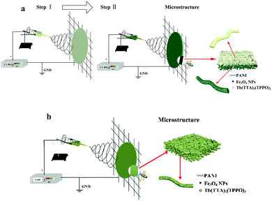 |
| | Fig. 1 Electrospinning process and schematic diagrams of the structures of the bi-layered composite nanofibrous film (a) and the single-layered composite nanofibrous film (b). | |
Characterization
The crystalline nature and phase structure of samples were examined using X-ray powder diffraction (XRD) performed on a Rigaku D/max-RA X-ray diffractometer with Cu Kα radiation (λ = 0.15406 nm) and a Ni filter, operating at 20 mA, 40 kV; the scanning speed, step length and diffraction range were 10° min−1, 0.1° and 10°–80°, respectively. The morphology and the thickness of the films were observed using a field emission scanning electron microscope (FESEM, JSM-7610F) equipped with an energy-dispersive X-ray spectrometer (EDS). The measurements of fluorescence spectra were performed using a HITACHI F-7000 fluorescence spectrophotometer with a 150 W Xe lamp as the excitation source, scanning speed at 1200 nm min−1. The excitation and emission slits were set to 1.0 nm and 2.5 nm, respectively. Fluorescence spectra are recorded for each sample in the solid state. Then, the magnetic performances of the samples were measured using a vibrating sample magnetometer (VSM, MPMS SQUID XL) at room temperature. Finally, the electrical conduction property was detected by using a four probe meter (RTS-4). All of the measurements were carried out at room temperature.
Results and discussion
Phase analyses
Fig. 2 shows the XRD results of Fe3O4 NPs, the bi-layered composite nanofibrous film and the counterpart single-layered composite nanofibrous film. It is noted that the diffraction peaks of the as-prepared Fe3O4 NPs can be readily indexed to the cubic phase of Fe3O4. The location and relative intensity of the diffraction peaks coincide well with the standard card (PDF#88-0866) of Fe3O4. The XRD patterns of the two sides of the bi-layered composite nanofibrous film are obviously different. When the electrical–magnetic layer faces the detector of the X-ray diffractometer, characteristic diffraction peaks of Fe3O4 can be detected. By contrast, no diffraction peaks of Fe3O4 can be observed when the fluorescent layer faces the detector. These results indicate that Fe3O4 NPs exist only in the electrical–magnetic layer, further implying that magnetism merely exists in the electrical–magnetic layer, not in the fluorescent layer. As for the counterpart single-layered composite nanofibrous film, diffraction peaks of Fe3O4 can be detected, indicating that Fe3O4 NPs are dispersed in the composite film and magnetism exists in the whole composite film. The broad diffraction peaks ranging from 15° to 25° in the composite nanofibrous films manifest the existence of amorphous PAN and PANI.
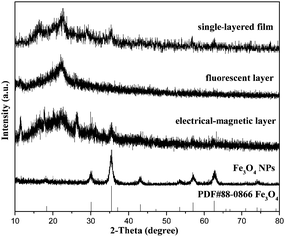 |
| | Fig. 2 XRD patterns of Fe3O4 NPs, the electrical–magnetic layer and the fluorescent layer of the [Tb(TTA)3(TPPO)2/PVP]/[PANI/Fe3O4/PVP] bi-layered composite nanofibrous film (S3) and the single-layered composite nanofibrous film. | |
Morphology and structure
Fig. 3 shows the SEM images, EDS spectra and histograms of the diameter distribution of the nanofibers in the films. As shown in Fig. 3a, the cross section of the bi-layered film can be clearly seen from the SEM image with low magnification. One can identify that the film is composed of two layers with different thicknesses. The thinner luminescent layer is ca. 122.59 μm in thickness, in which PVP is the template, while the thickness of the thicker electrical–magnetic layer whose template is PAN is about 300.63 μm. Fig. 3c and e show the SEM images of the luminescent layer and the electrical–magnetic layer at high magnification, respectively. It can be seen that the two layers are composed of crossed nanofibers. Fig. 3d and f demonstrate the histograms of the diameter distributions of the nanofibers in each layer. Under the 95% confidence level, the diameters of the nanofibers analyzed by the Shapiro–Wilk method are normally distributed. The average diameters are 400 ± 5.02 nm and 148 ± 1.15 nm for the nanofibers in the luminescent and electrical–magnetic layers, respectively. The energy dispersive spectrum shown in Fig. 3b reveals that the bi-layered composite nanofibrous film is composed of elements C, N, O, Fe, Tb, P, S and Pt. The Pt peak in the spectrum comes from the conductive film plated on the surface of the sample for SEM observation.
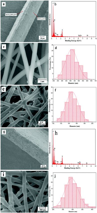 |
| | Fig. 3 SEM images of the cross section (×120) (a), the luminescent layer (×12k) (c), the electrical–magnetic layer (×30k) (e) and the EDS spectrum (b) of the bi-layered composite nanofibrous film; the histograms of the diameter distribution of the nanofibers in the luminescent layer (d) and the electrical–magnetic layer (f); SEM images of the cross section (×120) (g) and the surface (×20k) (i), the EDS spectrum (h) and the histogram of diameters (j) of the single-layered composite nanofibrous film. | |
At the same time, the morphology of the single-layered composite nanofibrous film is also observed. The cross section of the single-layered composite nanofibrous film shows an unstratified structure and is ca. 443.87 μm in thickness, as shown in Fig. 3g. Elemental C, O, Fe, Tb, P, S and Pt are also observed from the EDS spectrum in Fig. 3h. Fig. 3i reveals the SEM image of the nanofibers in the single-layered composite nanofibrous film. As seen from Fig. 3j, under the 95% confidence level, the diameters of the nanofibers analyzed by the Shapiro–Wilk method are normally distributed, and the average diameter of these nanofibers is 290 ± 0.8 nm.
The physical photos of the samples are presented in Fig. 4a–c. As seen from Fig. 4a, there is an obvious difference between the two layers of the bi-layered composite nanofibrous film. The luminescent layer is white (Fig. 4b), while the electrical–magnetic layer is blackish green (Fig. 4c) because of the existence of PANI and Fe3O4. One can see that the product has a unique and interesting bi-layered structure: its two layers reveal different colors due to the different compositions. The picture in the inset of Fig. 4b shows the green light emitted from the luminescent layer under 357 nm ultraviolet illumination in the dark. As indicated in Fig. 4d, the counterpart single-layered composite nanofibrous film is blackish green, but the color is lighter than that of the electrical–magnetic layer of the bi-layered composite nanofibrous film, which is because the white Tb(TTA)3(TPPO)2 RE complex is mixed with the dark-colored PANI and Fe3O4 NPs, leading to an overall lighter color.
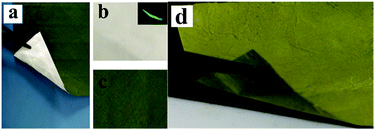 |
| | Fig. 4 Digital photos of the bi-layered composite nanofibrous film: a folded film (a), luminescent layer (b), electrical–magnetic layer (c), and single-layered composite nanofibrous film (d), and the inset of (b) shows the emitting light under 357 nm excitation light in the dark. | |
Fluorescence performance
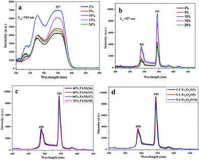
In order to study the fluorescence performance of the bi-layered composite nanofibrous film, a series of nanofibrous films doped with different percentages of Tb(TTA)3(TPPO)2 were fabricated while the mass percentage of PANI to PAN and the mass ratio of Fe3O4 to PAN were, respectively, fixed at 50% and 1:1. Fig. 5a and b demonstrate the excitation and emission spectra of the luminescent layer of the bi-layered composite nanofibrous films, in which the percentage of Tb(TTA)3(TPPO)2 is varied from 2% to 20% (samples S1–S5). As illustrated in Fig. 5a, there is a broad band extending from 200 nm to 400 nm for the various samples when the monitoring wavelength is 545 nm. The peak at 357 nm attributed to the π → π* electron transition of the ligands could also be identified. According to the emission spectra in Fig. 5b, strong characteristic emission peaks of Tb3+ are observed under the excitation of 357 nm ultraviolet light, which can be ascribed to the energy level transitions of 5D4 → 7F6 (490 nm), 5D4 → 7F5 (545 nm), 5D4 → 7F4 (582 nm) and 5D4 → 7F3 (618 nm), and the green emission at 545 nm assigned to 5D4 → 7F5 hypersensitive transition is the predominant emission peak. With the increase of Tb(TTA)3(TPPO)2 concentration, the fluorescence intensity gradually increases first and then decreases. The highest intensity is obtained when the mass percentage of Tb(TTA)3(TPPO)2 to PVP is 10%. The decrease of fluorescence intensity as the mass percentage of Tb(TTA)3(TPPO)2 to PVP exceeds 10% is attributed to the fluorescence quenching due to the fact that too much RE complex is introduced into the polymeric matrix.37,38 Therefore, 10% of Tb(TTA)3(TPPO)2 was adopted to prepare bi-layered composite nanofibrous films for the following study.
 |
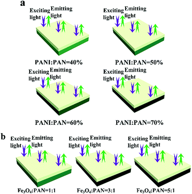
| | Fig. 5 Excitation (a) and emission (b, c and d) spectra of bi-layered composite nanofibrous films doped with different contents of Tb(TTA)3(TPPO)2 (a and b) at a PANI mass percentage of 50% and a Fe3O4 mass ratio of 1:1, PANI (c) and Fe3O4 NPs (d) at a Tb(TTA)3(TPPO)2 mass percentage of 10%. | |
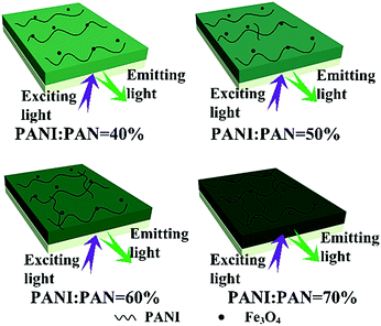
On the other hand, the luminescence property of the bi-layered composite nanofibrous films is also explored via modulating the mass percentage of PANI to PAN and the mass ratio of Fe3O4 to PAN. As shown in Fig. 5c and d, it is very interesting to find that no significant decrease of emission intensity of the luminescent layers in the bi-layered composite films is observed when the contents of PANI and Fe3O4 are varied. As seen from the schematic diagrams in Fig. 6, with the increase of PANI and Fe3O4 NPs contents, the color of the electrical–magnetic layer becomes darker, whereas the luminescence intensity remains constant. In other words, owing to the unique bi-layered structure, the electrical–magnetic layer has little impact on the luminescence property of the luminescent layer, despite the varied contents of PANI and Fe3O4 NPs in the electrical–magnetic layer. The new findings can be explained by that the new-type of bi-layered composite nanofibrous film ideally realizes the isolation of the electrical–magnetic layer from the luminescent layer, leading to almost no impact between the two layers.
 |
| | Fig. 6 Schematic diagrams of the exciting light and emitting light in bi-layered composite nanofibrous films at different percentages of PANI (a) and various ratios of Fe3O4 (b). | |
Besides, in order to further illustrate the advantages of the unique structure of the luminescent–electrical–magnetic trifunctional bi-layered film, the fluorescence properties of the luminescent layer and the electrical–magnetic layer of the bi-layered film are, respectively, investigated by comparing with those of the single-layered composite nanofibrous film. As shown in Fig. 7, one can see that no emission can be detected in the electrical–magnetic layer because the exciting light cannot pass through the electrical–magnetic layer and excite the Tb(TTA)3(TPPO)2 in the fluorescent layer, indicating that Tb(TTA)3(TPPO)2 does not mix with the electrical–magnetic layer. Thus, a conclusion can be safely drawn that the bi-layered film has different fluorescence properties in the two layers. Compared with the luminescent layer of the bi-layered film, the single-layered composite nanofibrous film exhibits very weak emissions of Tb3+. Fig. 8 presents the schematic diagrams revealing the comparison of the photoluminescence property of the bi-layered film (luminescent layer) and the single-layered film. As for the single-layered composite nanofibrous film, Tb(TTA)3(TPPO)2 directly contacts with deep-colored PANI and Fe3O4 NPs which strongly absorb and weaken exciting and emitting light, leading to a severe decrease in luminescence intensity.38 In contrast, because the luminescent layer and the electrical–magnetic layer are separated in the bi-layered film, the luminescence property of the luminescent layer remains almost unaffected by the electrical–magnetic layer. This result fully demonstrates that the bi-layered composite nanofibrous film exhibits better fluorescence properties.
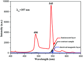 |
| | Fig. 7 Emission spectra of the luminescent layer and the electrical–magnetic layer in the bi-layered composite nanofibrous film (S3) and the single-layered composite nanofibrous film as the contrast sample. | |
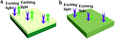 |
| | Fig. 8 Schematic diagrams of the exciting light and emitting light in the bi-layered composite nanofibrous film (a) and the single-layered composite nanofibrous film (b). | |
Electrical conductivity
The electrical properties of both layers of the bi-layered composite nanofibrous film were investigated. For the testing samples, the mass percentage of Tb(TTA)3(TPPO)2 to PVP and the mass ratio of Fe3O4 to PAN were, respectively, fixed at 10% and 1:1, and the mass percentages of PANI to PAN were varied from 40%, 50%, 60% to 70%. The electrical conductivities of the bi-layered composite nanofibrous film (electrical–magnetic layer) and the single-layered composite nanofibrous film are summarized in Table 3. All those conductivities were tested 3 times and the final data were the average results. The conductivity of PANI depends on the connectivity of the conductive network which provides charge transport.39,40 It can be seen that as the mass percentage of PANI increases, higher conductivity can be achieved, and the electrical–magnetic layer becomes darker. As for the luminescent layer, the electrical conductivity value cannot be obtained by using a four probe meter, which is used to characterize conductors, meaning that the luminescent layer is insulative. The schematic diagram of the color gradient which represents the different mass percentages of PANI to PAN is shown in Fig. 9. Because PANI is dark green, it is reasonable that the green color of the electrical–magnetic layer becomes darker when more PANI is introduced. It is found from Table 3 that as the dosage of PANI increases, the conductivity of the electrical–magnetic layer enhances dramatically, meaning that the electrical conductivity of the composite film can be readily tuned. The conductivity of the electrical–magnetic layer of the bi-layered film (Sa4/Sb2) is slightly higher than that of the single-layered film. The reason is probably that insulating materials such as Fe3O4 NPs, Tb(TTA)3(TPPO)2, PVP and PAN are all dispersed in the single-layered composite nanofibrous film, resulting in hindrance to the formation of the continuous conducting network.
Table 3 Electrical conductivities of the electrical–magnetic layer of the samples doped with various amounts of PANI
| Samples |
PANI contents (%) |
Conductivity (S cm−1) |
| measurements |
Average data (S cm−1) |
| S6 |
PANI:PAN = 40 |
8.62 × 10⁻⁴ |
7.23 × 10⁻⁴ |
| 7.63 × 10⁻⁴ |
| 5.43 × 10⁻⁴ |
|
|
| S3 |
PANI:PAN = 50 |
4.62 × 10⁻³ |
5.12 × 10⁻³ |
| 4.38 × 10⁻³ |
| 6.35 × 10⁻³ |
|
|
| S7 |
PANI:PAN = 60 |
9.98 × 10⁻³ |
1.49 × 10⁻² |
| 2.41 × 10⁻² |
| 1.06 × 10⁻² |
|
|
| S8 |
PANI:PAN = 70 |
9.75 × 10⁻² |
8.43 × 10⁻² |
| 7.34 × 10⁻² |
| 8.19 × 10⁻² |
|
|
| Contrast sample |
PANI:PAN = 50 |
3.59 × 10⁻³ |
4.31 × 10⁻³ |
| 5.47 × 10⁻³ |
| 3.86 × 10⁻³ |
 |
| | Fig. 9 Schematic diagrams of the bi-layered composite nanofibrous films containing different mass percentages of PANI to PAN. | |
Magnetic properties
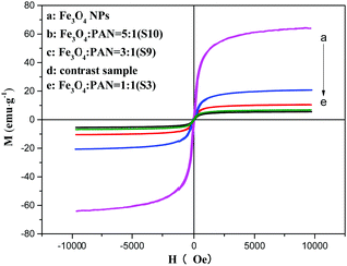
The typical hysteresis loops of Fe3O4 NPs, bi-layered composite nanofibrous films with different mass ratios of Fe3O4 NPs and the contrast sample single-layered composite nanofibrous film are shown in Fig. 10, and their saturation magnetization values are listed in Table 4. As seen from Table 4, along with the increase of the mass ratio of Fe3O4 NPs, the saturation magnetization of the bi-layered composite nanofibrous film is increased from 3.5 emu g−1 to 8.4 emu g−1, implying that the composite films possess tunable magnetism. The bi-layered film (S3) exhibits magnetic properties similar to the single-layered composite nanofibrous film, which is because they have the same adding Fe3O4 contents. The schematic diagram of the bi-layered composite nanofibrous film containing different mass ratios of Fe3O4 to PAN is depicted in Fig. 11. As indicated in Fig. 11, the color in the electrical–magnetic layer of the bi-layered composite nanofibrous film changed from yellowish-green to dark green with the increase of Fe3O4 contents. This is because black Fe3O4 NPs darken the color of the electrical–magnetic layer.
 |
| | Fig. 10 Hysteresis loops of the Fe3O4 NPs, single-layered composite nanofibrous film and bi-layered nanofibrous films at different Fe3O4 mass ratios. | |
Table 4 Saturation magnetization of Fe3O4 NPs, the single-layered composite nanofibrous film and [Tb(TTA)3(TPPO)2/PVP]/[PANI/Fe3O4/PVP] bi-layered composite nanofibrous films at different Fe3O4 mass ratios
| Samples |
Saturation magnetization (Ms)/[emu g−1] |
| Fe3O4 NPs |
63.98 |
| Contrast sample |
6.78 |
| S3 (Fe3O4:PVP) = 1:1 |
5.56 |
| S9 (Fe3O4:PVP) = 3:1 |
10.46 |
| S10 (Fe3O4:PVP) = 5:1 |
20.76 |
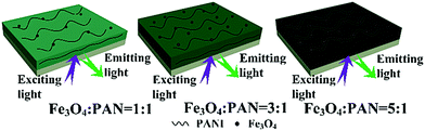 |
| | Fig. 11 Schematic diagrams of bi-layered composite nanofibrous films containing different mass ratios of Fe3O4 to PAN. | |
Judging from the above analysis of luminescence, electricity and magnetism, we can reasonably reach the conclusion that the bi-layered nanofibrous film exhibits better performances than its counterpart single-layered film.
Conclusions
In summary, a kind of brand-new trifunctional bi-layered composite nanofibrous film endowed with luminescence at one layer, and magnetism and electrical conduction at the other layer was successfully fabricated for the first time via electrospinning by means of altering the spinning solutions one by one during the electrospinning process. The thicknesses of the luminescent layer and the electrical–magnetic layer are, respectively, 122.59 μm and 300.63 μm. The electrical conductivity and magnetic properties of the bi-layered composite nanofibrous film can be, respectively, tuned by adding different amounts of PANI and Fe3O4 NPs. Furthermore, it is very gratifying to see that the bi-layered composite nanofibrous film shows excellent luminescence properties almost without the impact of the PANI and Fe3O4 NPs. Owing to these versatile properties, the novel membranous trifunctional material obtained by assembling 1D materials into a 2D macroscopic architecture can be used in the fields of full-color displays, electromagnetic shielding, and nanodevices. More importantly, the new design conception and membranous construction technology are of universal significance to design and fabricate new types of multifunctional materials.
Acknowledgements
This work was financially supported by the National Natural Science Foundation of China (51573023, 50972020, 51072026), and the Science and Technology Development Planning Project of Jilin Province (20130101001JC, 20070402).
Notes and references
- F. Bi, X. T. Dong, J. Wang and G. Liu, J. Mater. Sci., 2014, 49, 7244–7252 CrossRef CAS.
- D. Li, X. T. Dong, W. S. Yu, J. X. Wang and G. X. Liu, J. Nanopart. Res., 2013, 15, 1–10 Search PubMed.
- R. A. Patil, C.-P. Chang, R. S. Devan, Y. Liou and Y.-R. Ma, ACS Appl. Mater. Interfaces, 2016, 8, 9872–9880 CAS.
- Q. J. Wang, J. Qian, Y. Li, Y. H. Zhang, D. W. He, S. Jiang, Y. Wang, X. R. Wang, L. J. Pan, J. Z. Wang, X. Z. Wang, Z. Hu, H. Y. Nan, Z. H. Ni, Y. D. Zheng and Y. Shi, Adv. Funct. Mater., 2016, 26, 3191–3198 CrossRef CAS.
- B. Lan, L. Yu, T. Lin, G. Cheng, M. Sun, F. Ye, Q. F. Sun and J. He, ACS Appl. Mater. Interfaces, 2013, 5, 7458–7464 CAS.
- A. Vaterrodt, B. Thallinger, K. Daumann, D. Koch, G. M. Guebitz and M. Ulbricht, Langmuir, 2016, 32, 1347–1359 CrossRef CAS PubMed.
- J. Zhu, X. Yang, Z. Fu, J. He, C. Wang, W. Wu and L. Zhang, Chem. – Eur. J., 2016, 22, 2515–2524 CrossRef CAS PubMed.
- S. Peng, L. Li, Y. Hu, M. Srinivasan, F. Cheng, J. Chen and S. Ramakrishna, ACS Nano, 2015, 9, 1945–1954 CrossRef CAS PubMed.
- K. Li, M. M. Shang, H. Z. Lian and J. Lin, J. Mater. Chem. C, 2016, 4, 5507–5530 RSC.
- Z. Y. Hou, G. G. Li, H. Z. Lian and J. Lin, J. Mater. Chem., 2012, 22, 5254–5276 RSC.
- C. M. Zhang and J. Lin, Chem. Soc. Rev., 2012, 41, 7938–7961 RSC.
- Z. Q. Li, Y. Zhang and S. Jiang, Adv. Mater., 2009, 21, 4765–4769 Search PubMed.
- R. Zhao, Y. Wang, X. Li, B. L. Sun and C. Wang, ACS Appl. Mater. Interfaces, 2015, 7, 26649–26657 CAS.
- F. J. Miao, C. L. Shao, X. H. Li, K. X. Wang, N. Lu and Y. C. Liu, ACS Sustainable Chem. Eng., 2016, 4, 1689–1696 CrossRef CAS.
- G. A. S. Josephine, U. M. Nisha, G. Meenakshi and A. Sivasamy, Ecotoxicol. Environ. Saf., 2015, 121, 67–72 CrossRef PubMed.
- W. Lu, W. Z. Lv, Q. Zhao, M. M. Jiao, B. Shao and H. P. You, J. Mater. Chem. C, 2015, 3, 2334–2340 RSC.
- L. Y. Wang, Z. H. Yang, Y. Zhang and L. Wang, J. Phys. Chem. C, 2009, 113, 3955–3959 CAS.
- Q. L. Ma, J. X. Wang, X. T. Dong, W. S. Yu, G. X. Liu and J. Xu, J. Mater. Chem., 2012, 22, 14438–14442 RSC.
- Z. Y. Ma, D. Dosev, M. Nichkova, S. J. Gee, B. D. Hammock and I. M. Kennedy, J. Mater. Chem., 2009, 19, 4695–4700 RSC.
- M. Runowski, T. Grzyb and S. Lis, J. Rare Earths, 2011, 29, 1117–1122 CrossRef CAS.
- Q. Wang, X. W. Yang, L. X. Yu and H. Yang, J. Alloys Compd., 2011, 509, 9098–9104 CrossRef CAS.
- S. L. Gai, P. P. Yang, C. X. Li, W. X. Wang, Y. L. Dai, N. Niu and J. Lin, Adv. Funct. Mater., 2010, 20, 1166–1172 CrossRef CAS.
- D. H. Zhang and Y. Y. Wang, Mater. Sci. Eng., B, 2006, 134, 9–19 CrossRef CAS.
- J. T. Zhang, J. Wang, J. E. Yang, Y. L. Wang and M. B. Chan-Park, ACS Sustainable Chem. Eng., 2014, 2, 2291–2296 CrossRef CAS.
- Y. W. Liu, Q. L. Ma, M. Yang, X. T. Dong, Y. Yang, J. X. Wang, W. S. Yu and G. X. Liu, Chem. Eng. J., 2016, 284, 831–840 CrossRef CAS.
- X. Y. Xu and B. Yan, ACS Appl. Mater. Interfaces, 2015, 7, 721–729 CAS.
- N. Lv, X. Dong, Q. Ma, J. Wang, W. Yu and G. Liu, J. Mater. Sci., 2014, 49, 2171–2179 CrossRef CAS.
- X. F. Lu, C. Wang and Y. Wei, Small, 2009, 5, 2349–2370 CrossRef CAS PubMed.
- D. Li, J. X. Wang, X. T. Dong, W. S. Yu and G. X. Liu, J. Mater. Sci., 2013, 48, 5930–5937 CrossRef CAS.
- S. De Vrieze, T. Van Camp, A. Nelvig, B. Hagström, P. Westbroek and K. De Clerck, J. Mater. Sci., 2008, 44, 1357–1362 CrossRef.
- S. Torres-Giner, R. Pérez-Masiá and J. M. Lagaron, Polym. Eng. Sci., 2016, 56, 500–527 CAS.
- N. Lv, Z. G. Wang, W. Z. Bi, G. M. Li, J. L. Zhang and J. Z. Ni, J. Mater. Chem. B, 2016, 4, 4402–4409 RSC.
- S. U. Maheshwari, S. V. Kumar, N. Nagiah and T. S. Uma, Polym. Bull., 2013, 70, 2995–3010 CrossRef CAS.
- J. Wu, N. Wang, L. Wang, H. Dong, Y. Zhao and L. Jiang, Soft Matter, 2012, 8, 5996–5999 RSC.
- H.-C. Yang, J. Hou, V. Chen and Z.-K. Xu, Angew. Chem., Int. Ed., 2016, 55, 13398–13407 CrossRef CAS PubMed.
- J. Tian, Q. L. Ma, X. T. Dong, M. Yang, Y. Yang, J. X. Wang, W. S. Yu and G. X. Liu, J. Mater. Sci.: Mater. Electron., 2015, 26, 8413–8420 CrossRef CAS.
- K. Lun, Q. L. Ma, X. T. Dong, W. S. Yu, J. X. Wang and G. X. Liu, J. Mater. Sci.: Mater. Electron., 2014, 25, 5395–5402 CrossRef CAS.
- Y. X. Liu, G. X. Liu, X. Dong, J. X. Wang and W. S. Yu, Phys. Chem. Chem. Phys., 2015, 17, 26638–26644 RSC.
- Q. L. Ma, J. X. Wang, X. T. Dong, W. S. Yu and G. X. Liu, Adv. Funct. Mater., 2015, 25, 2436–2443 CrossRef CAS.
- H. Shao, Q. Ma, X. Dong, W. Yu, M. Yang, Y. Yang, J. Wang and G. Liu, Sci. Rep., 2015, 5, 14052 CrossRef CAS PubMed.
|
| This journal is © the Owner Societies 2017 |
Click here to see how this site uses Cookies. View our privacy policy here. 


