Photocatalytic air-purification: a low-cost, real-time gas detection method
Donal A.
Keane
 *ad,
Niki
Hamilton
b,
Lorraine T.
Gibson
b,
Suresh. C.
Pillai
c,
Justin D.
Holmes
de and
Michael A.
Morris
e
aEnvironmental Research Institute, University College Cork, Lee Road, Cork, Ireland. E-mail: donal.keane@ucc.ie
bDepartment of Pure and Applied Chemistry, WestCHEM, University of Strathclyde, 295 Cathedral Street, UK
cNanotechnology and Bio-Engineering Research Group, Department of Environmental Science, School of Science, Institute of Technology Sligo, Ash Lane, Sligo, Ireland
dDepartment of Chemistry, University College Cork, Cork, Ireland
eAMBER (Advanced Material and Bio-Engineering Research Centre), Trinity College Dublin, Dublin-2, Ireland
First published on 1st December 2016
Abstract
This research demonstrates the use of a gas detector as a feasible alternative to the standardized analytical methods typically found in photocatalytic air-purification ISO standard tests and academic literature. A methyl mercaptan detector is calibrated and validated (for linearity) using a standard gas generator. The detector can be directly connected to the photoreactor exit allowing real-time span gas measurement with data-logging at one minute intervals. The detector successfully differentiated samples with different photocatalytic performance. The use of such detectors offers an easy-to-use, low-cost alternative to gas measurement with applications in academic research, proof-of-concept photocatalytic tests and also as an educational tool.
1. Introduction
Photocatalysts are materials, which can accelerate chemical reactions by absorbing light quanta of suitable wavelengths depending on the band structure.1–7 Photocatalysts find a wide range of industrial applications ranging from self-cleaning materials to water purification.3 For an overview of gas phase photocatalytic air-purification, the reader is referred to the recent review by Verbruggen.8 Various ISO (the International Organization for Standardization) methods have been implemented to analyse the effectiveness of various types of photocatalysts, which can be employed by industries to test the products and thereby to ensure the quality of the product.3To date, there are five ISO photocatalytic air-purification test standards for the following test gases: nitric oxide (NO),9 acetaldehyde (CH3CHO),10 toluene (C6H5O),11 formaldehyde (CH3O)12 and methyl mercaptan (CH3SH).13 In 2012, Mills et al.14 reviewed the first three standards available at the time. As the authors point out, one of the disadvantages of the standards is that each individual sub-test requires expensive and different analytical equipment (listed here in Table 1). Other analytical methods such as ion chromatography (NO3−) and an infrared analyser (CO2) are recommended in the first two standards9,10 to measure photocatalytic by-products. Interestingly, the final three standards11–13 only describe measurement of the pollutant test gas. It was also pointed out that technical support and training is often needed for operation and maintenance of these analytical methods.14 Although the gas chromatographic methods are powerful and can quantitatively identify and measure photocatalytic by-products, the expense in cost and experimental person-hours can cause researchers to struggle to build the apparatus and also lose focus and time on the original goal of the standards (to test photocatalytic performance). Concerns such as these were described as ‘possibly unavoidable’.14 In this study we address the issue by employing a low-cost, commercially available “off-the-shelf” gas monitor as an alternative gas analyser for measurement of the fifth ISO standard test gas (methyl mercaptan)13 in photocatalytic air-purification tests.
| Test gas | Analytical method |
|---|---|
| a CA – chemiluminescent analyser, GC – gas chromatography, FID – flame ionization detector, PID – photo ionization detector, DNPH/HPLC – 2,4 dinitrophenylhydrazine derivatised high-performance liquid chromatography, FPD – flame photometric detector. | |
| Nitric oxide | CA |
| Acetaldehyde | GC-FID/PID DNPH/HPLC |
| Toluene | GC-FID/PID |
| Formaldehyde | DNPH/HPLC |
| Methyl mercaptan | GC-FID/FPD |
Although gas detectors used in photocatalytic experimental setups have been reported in the literature (a good example of a fixed methyl mercaptan detector is from Li et al.15), such instances are rare, and not the primary purpose of the studies. Emerging analytical methods have also recently been proposed as alternatives to the ubiquitous GC methods described above in photocatalytic air-purification. Ireland et al.16 employed Field Asymmetric Ion Mobility Spectrometry (FAIMS) to analyse the photo-oxidation of indoor volatile organic compound (VOC) air pollutants. Yao et al.17 used Proton Transfer Reaction Mass Spectrometry (PTR-MS) to characterise the photocatalytic degradation of odorous compounds associated with livestock. Both of these new analytical methods rival the standardized GC methods in terms of specification but do not address the principal concern of Mills et al.14 regarding cost and ease of use. In another interesting study, Stefanov et al.18 employed commercially available semiconductor gas sensors in a 3-D printed photocatalysis reactor. However, using such sensors require supporting electronics for digital readout and is not a “ready-to-use” gas detection system.
The low-cost detector used in this study (Honeywell ToxiRae Pro) is portable, has on-line data logging capability and is inherently user-friendly as its primary purpose is in chemical site safety. Following analytical validation tests to determine linearity, the photocatalytic removal of methyl mercaptan is demonstrated employing glass beads coated with Aeroxide P25 titanium dioxide (TiO2). The advantages and disadvantages of employing such detectors are discussed as well as suitable applications and future research.
2. Materials and methods
2.1 Materials
The calibration methyl mercaptan gas is generated using a standard gas generator (Kin-Tek 491 MB). The generator employs NIST traceable permeation tubes as the span gas source. Both the generator and permeation tubes were supplied by Eco-Scientific Limited. The variable area flow controller and all tubing were supplied by Fischer Scientific. All valves were supplied by Swagelok. The gas chambers, Drechsel bottle and photoreactor tubes (90 mm length, 8 mm outer diameter, 5 mm inner diameter) were made by an in-house glass-blower. Aeroxide P25 TiO2 powder, glass beads (710–1180 μm) and glass wool were supplied by Sigma-Aldrich. The ToxiRae Pro (Honeywell, Rae Systems) gas monitor with CH3SH electrochemical sensor (range: 0–10 ppm, resolution: 0.1 ppm) was supplied by Envirosafe Ireland. The humidity/temperature logger (Onset HOBO MX1101) was supplied by Tempcon Instrumentation Limited. The UV lamp (Uvitec LI206BL Black-Light unfiltered UV longwave lamp) was purchased from Accuscience.2.2 Gas detector calibration and validation
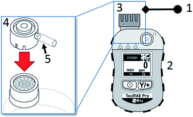
A methyl mercaptan gas detector (ToxiRae Pro) was employed as a test detector. Prior to each use the detector is calibrated by a connection via an adapter supplied with the detector to a gas standards generator as shown in Fig. 1. The detector head is purged with calibration gas for 30 minutes prior to internal instrument detector calibration (1 min). The linearity validation test was performed by supplying the calibration span gas over a range indicated by the ISO standard13 (0–5 ppm) by changing the flow rate using a mass flow controller housed within the gas standard generator. The measured detector concentration was recorded at one minute intervals.2.3 Preparation of photocatalytic tubes
Photocatalytic test materials were prepared by coating glass beads with Aeroxide P25 TiO2 powder (Sigma Aldrich) using methods similar to those reported by Basha et al.19 6 g of glass beads, 0.6 g of P25 powder and 240 cm3 of deionised water were placed in sealed 250 cm3 Schott glass bottle and sonicated in a bath for 1 hour at room temperature. The top of the bottle is removed and the bottle is placed in an oven at 110 °C overnight. The dried and coated beads are removed, and the excess TiO2 powder is removed by repeated washing with deionised water and sieving through a Test Sieve (Fisherbrand 200 mm diameter × 500 μm). The coated and uncoated beads are imaged by Scanning Electron Microscopy (SEM) (JEOL model FEI FP 2031/11 inspect F field emission scanning electron microscope). Fixed quantities (2, 1.5, 1.0 and 0.5 g) of the powder coated beads from the same batch are packed into glass photoreactor tubes between glass wool (Sigma Aldrich) and retaining springs (Markes International) for the photocatalytic air-purification tests.2.4 Experimental test setup
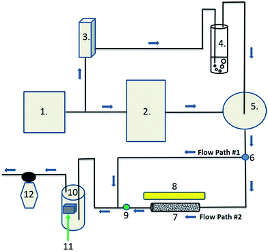
The photocatalytic air-purification test setup shown schematically in Fig. 2, has features from different reported setups including the ISO standards,9–13 Idris et al.,20 Yu et al.21 and Destaillats et al.22 Compressed air is supplied to both the gas standards generator and the Drechsel bottle. The span gas is humidified in a gas-mixing chamber and flows directly (flow path #1) to the humidity detector in the gas detection chamber, followed by the gas detector. The flow rate of the span gas and diluent humidified air are adjusted in the gas standards generator and variable area flow controller respectively, such that stable readings of 5.0 ± 0.3 ppm CH3SH and 50 ± 5% relative humidity are observed by the detectors. The plug valve and 3-way valve are then opened allowing the test gas to flow though the photoreactor tube to both detectors (flow path #2). Adsorption is observed by reduction in the CH3SH reading on the detector. Once the reading returns to 5 ppm, the UV lamp is turned on to test the photocatalytic performance of the powder coated sample over a 3 hour period after which the lamp is turned off to ensure a return of the test gas to within 10% of the test concentration.3. Results and discussion
3.1 Gas detector validation
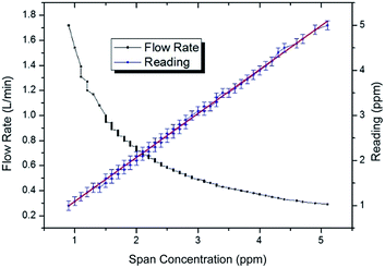
The span gas target concentration was reduced from 5 to 0.9 ppm at one minute intervals by modifying the flow rate across the permeation tube† from 0.29 to 1.72 L min−1 with 80 data points. Fig. 3 shows that the CH3SH detector gives a highly linear response with an R2 value of 0.999 and y-intercept of 0.11881. Both of these values can be considered as a good linearity fit as part of a general analytical method validation,23 and thus fit for purpose as a detector in the photocatalytic air-purification test setup.3.2 Photocatalytic air-purification tests
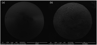
Four samples with different quantities (2, 1.5, 1.0 and 0.5 g) of TiO2 coated glass beads from the same batch were tested in the photocatalytic test setup to demonstrate the applicability of the gas detector i.e. that the “method can differentiate (the) samples with different photocatalytic performance”.9–11 The coating method produced a thin film of TiO2 as shown by equal magnification SEM in Fig. 4. As opposed to TiO2 in powder form, the coated beads showed minimal adsorption satisfying the ISO adsorption requirement: that the gas concentration at the outlet of the reactor returns to supply gas concentration within 30 minutes. To the naked eye the coated beads in the glass photoreactor tubes were semi-transparent allowing adequate UV illumination of the photocatalyst surface. Quantities of coated beads were tested allowing removal of CH3SH within the range of that reported in the ISO standard13 (0–5 ppm).As shown in Fig. 5 and Table 2, the gas detector was able to quantify the removal of the test CH3SH pollutant gas of different performing photocatalytic coatings in a satisfactory manner, the primary goal of the ISO standard. Greater accuracy is obtained due to the data-logging capability of the detector in which 60 data points in the last hour of the test can be averaged to obtain ϕM (averaged concentration at reactor exit). This is in comparison to the ISO standards, which recommend ϕM should be the average of at least three or more measurements. Without an automatic sampling system connecting the photoreactor outlet to the detector, the manual sampling of >3ϕM measurements would prove to be laborious and prone to irreproducibility due to human error. For these reasons, the typical concentration versus time trace in some of the ISO standards can have a low number of data points per hour due to manual sampling (e.g. 3 data points per hour in the CH3SH standard13). The other standards which have automatic sampling to the gas analyser9–11 have graphical data sets similar to that shown in Fig. 5.
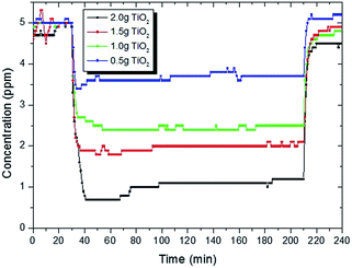 | ||
| Fig. 5 Concentration versus time data profile of methyl mercaptan during the test operation using differing quantities of TiO2 coated glass beads. | ||
| Sample | # Data pointsa | ϕ M0 | ϕ M | R M |
|---|---|---|---|---|
| a Data points extracted from ToxiRae Pro monitor to personal computer via USB. b ϕ M0 is the supply concentration of methyl mercaptan (ppm). c ϕ M is the averaged (60 data points) concentration of methyl mercaptan at reactor exit (ppm). d R M is the removal percentage of methyl mercaptan calculated by: RM = (ϕM0 − ϕM)/ϕM0. | ||||
| 2.0 g TiO2 | 60 | 5.0 | 1.1 | 78% |
| 1.5 g | 60 | 5.0 | 2.0 | 60% |
| 1.0 g | 60 | 5.0 | 2.5 | 50% |
| 0.5 g | 60 | 5.0 | 3.7 | 26% |
3.3 Gas detectors as “pollutant-measurement equipment”
At a first glance at the schematic diagram of the overall test equipment in the ISO standards, the “pollutant-measurement equipment” appears straight-forward (Fig. 6(a)), with a basic setup in which the test gas line is connected to an “analyser” followed by a sampling pump. However, further information on the analyser reveals a more complicated gas sampling system in which a 6-way valve is recommended for reproducible and automatic sampling (Fig. 6(b)). The use of a portable gas monitor, as used in this study, greatly simplifies the measurement of the test gas at the reactor outlet. The detector can be directly connected to the photoreactor outlet without the need of a sampling pump (Fig. 1.), or alternatively, due to its compact size, it could be placed within a small detection chamber. Overall, the advantages and disadvantages of using such a detector are described in Table 3. The disadvantages could be overcome by complete validation of the detector compared to the GC standard methods, use of multi-gas detector that measures by-product and use of a detector with higher specification that has lower detection limit of parts per billion (ppb). Such detectors would require additional cost, but would still remain low relative to GC analytical methods and could provide a satisfactory “middle ground”. With advances in miniaturization of detectors and sensors, the acquirement of commercially viable products with increasing sensitivity is emerging.24| Advantages | Disadvantages |
|---|---|
| ✓ Low cost | ✗ Not fully standardised and requires further validation |
| ✓ Real-time data logging | ✗ Not possible to measure by-products |
| ✓ Compact, portable and user-friendly | ✗ Detection limit of 0.1 ppm |
As an aside, it is interesting to note that in the formaldehyde (CHO) photocatalytic standard12 published after the review of Mills et al.,14 it is stated that other analytical methods that give equivalent or better performance can be used. This statement is not in any of the other four standards and can only be assumed to be included due to concerns over the use of the DNPH/HPLC as an analytical method that provides an accurate dataset. No information is provided whether the alternative analytical methods need to follow industrial standards. Indeed, in the case of this standard for the removal of CHO chosen as a typical pollutant responsible for sick building syndrome, there is scope to employ a low cost gas detector similar to the example in this study, as a large number of instruments are on the market.
Despite the successful demonstration described in the current study, the use of gas detectors is not standardised and as-such they cannot be recommended as alternatives to the standardized analytical methods used in the ISO photocatalytic standards. What is required is a full validation study directly comparing the detectors to the existing analytical methods shown in Table 1. For example, Mills et al.25,26 demonstrated photocatalytic indicator inks as an alternative to existing ISO tests for rapidly assessing the activities of photocatalytic surfaces. An inter-laboratory test was completed to establish repeatability and reproducibility26 and thus the precision27 of their proposed test method. Similar “round-robin” tests were undertaken in the first three photocatalytic gas purification test standards.9–11 In this respect, whereas the ISO photocatalytic standards are used for the development, quality assurance and design data generation of photocatalytic materials,9–13 we suggest the use of a gas detector is currently more suitable for academic research and proof of concept evaluations. Indeed, it could be envisioned that the detectors could be used in undergraduate or second-level (high-school) education to demonstrate photocatalytic air-purification. This would expose younger scientists to the air-purification method, which is currently somewhat inaccessible due to the complexity and cost of the test setup. The construction of an inexpensive, easy-to-use overall test setup (including gas detectors) for educational/proof of concept purposes is worthy of future work. Even in these proposed applications it is important that preliminary validation such as linearity is carried out prior to testing. As a case in point, early findings have shown that the ToxiRae Pro employing the formaldehyde electrochemical sensor (resolution: 0.01 ppm) did not perform as well as the methyl mercaptan sensor did in this study.
4. Conclusions
Through method validation (linearity) and differentiation of sample performance, the use of a commercial gas detector is shown to be a suitable analytical method for photocatalytic air-purification of methyl mercaptan. The advantages such as low-cost, ease-of-use and data-logging capability make it an attractive alternative to existing gas chromatographic methods. Similar studies with other detectors/sensors would demonstrate wider application to other pollutant gases. Full validation with an inter-laboratory study and comparison to existing standardized gas chromatographic methods would be necessary for use of such detectors in quality assurance and commercialization of photocatalytic materials. Nevertheless, the data generated in this study shows that gas detectors can have sufficient accuracy for use in academic photocatalytic air-purification tests.Acknowledgements
This research was funded by the Irish Environmental Protection Agency (EPA), EPA Research Programme 2014-2020. DAK would like to thank Stephen Durrant (Eco-Scientific Limited) for helpful discussion and advice regarding gas calibration employing permeation tubes. DAK would also like to thank Una O' Mahony (Department of Chemistry, University College Cork) for laboratory assistance.Notes and references
- J. Schneider, M. Matsuoka, M. Takeuchi, J. L. Zhang, Y. Horiuchi, M. Anpo and D. W. Bahnemann, Chem. Rev., 2014, 114, 9919–9986 CrossRef CAS PubMed
.
- V. Etacheri, C. Di Valentin, J. Schneider, D. Bahnemann and S. C. Pillai, J. Photochem. Photobiol., C, 2015, 25, 1–29 CrossRef CAS
.
- S. Banerjee, D. D. Dionysiou and S. C. Pillai, Appl. Catal., B, 2015, 176–177, 396–428 CrossRef CAS
.
- N. B. Rahna, V. Kalarivalappil, M. Nageri, S. C. Pillai, S. J. Hinder, V. Kumar and B. K. Vijayan, Mater. Sci. Semicond. Process., 2016, 42(3), 303–310 CrossRef CAS
.
- S. Banerjee, S. C. Pillai, P. Falaras, K. E. O'Shea, J. A. Byrne and D. D. Dionysiou, J. Phys. Chem. Lett., 2014, 5, 2543–2554 CrossRef CAS PubMed
.
- F. Dong, H. T. Liu, W. K. Ho, M. Fu and Z. B. Wu, Chem. Eng. J., 2013, 214, 198–207 CrossRef CAS
.
- F. Dong, Z. Wang, Y. Li, W.-K. Ho and S. C. Lee, Environ. Sci. Technol., 2014, 48, 10345–10353 CrossRef CAS PubMed
.
- S. W. Verbruggen, J. Photochem. Photobiol., C, 2015, 24, 64–82 CrossRef CAS
.
-
ISO 22197-1: 2007, Fine ceramics, advanced technical ceramics – test method for air-purification performance of semiconducting photocatalytic materials – part 1: removal of nitric oxide, ISO, Geneva, 2007 Search PubMed
.
-
ISO 22197-2: 2011, Fine ceramics, advanced technical ceramics – test method for air-purification performance of semiconducting photocatalytic materials – part 2: removal of acetaldehyde, ISO, Geneva, 2011 Search PubMed
.
-
ISO 22197-3: 2011, Fine ceramics, advanced technical ceramics – test method for air-purification performance of semiconducting photocatalytic materials – part 3: removal of toluene, ISO, Geneva, 2011 Search PubMed
.
-
ISO 22197-4: 2013, Fine ceramics, advanced technical ceramics – test method for air-purification performance of semiconducting photocatalytic materials – part 4: removal of formaldehyde, ISO, Geneva, 2013 Search PubMed
.
-
ISO 22197-5: 2013, Fine ceramics, advanced technical ceramics – test method for air-purification performance of semiconducting photocatalytic materials – part 5: removal of methyl mercaptan, ISO, Geneva, 2013 Search PubMed
.
- A. Mills, C. Hill and P. K. J. Robertson, J. Photochem. Photobiol., A, 2012, 237, 7–23 CrossRef CAS
.
- X. Z. Li, M. F. Hou, F. B. Li and H. Chua, Ind. Eng. Chem. Res., 2006, 45, 487–494 CrossRef CAS
.
- C. P. Ireland and C. Ducati, J. Photochem. Photobiol., A, 2015, 312, 1–7 CrossRef CAS
.
- H. Yao and A. Feilberg, Chem. Eng. J., 2015, 277, 341–351 CrossRef CAS
.
- B. I. Stefanov, D. Lebrun, A. Mattsson, C. G. Granqvist and L. Osterlund, J. Chem. Educ., 2015, 92, 678–682 CrossRef CAS
.
- S. Basha, D. Keane, A. Morrissey, K. Nolan, M. Oelgemoller and J. Tobin, Ind. Eng. Chem. Res., 2010, 49, 11302–11309 CrossRef CAS
.
- S. A. Idris, C. Robertson, M. A. Morris and L. T. Gibson, Anal. Methods, 2010, 2, 1803–1809 RSC
.
- Q. L. Yu and H. J. H. Brouwers, Appl. Catal., B, 2009, 92, 454–461 CrossRef CAS
.
- D. Kibanova, M. Sleiman, J. Cervini-Silva and H. Destaillats, J. Hazard. Mater., 2012, 211, 233–239 CrossRef PubMed
.
-
D. C. Harris, Quantitative Chemical Analysis, Quality Assurance and Calibration Methods, 2007, ch. 5 Search PubMed
.
- X. Liu, S. T. Cheng, H. Liu, S. Hu, D. Q. Zhang and H. S. Ning, Sensors, 2012, 12, 9635–9665 CrossRef PubMed
.
- A. Mills, J. Hepburn, D. Hazafy, C. O'Rourke, J. Krysa, M. Baudys, M. Zlamal, H. Bartkova, C. E. Hill, K. R. Winn, M. E. Simonsen, E. G. Sogaard, S. C. Pillai, N. S. Leyland, R. Fagan, F. Neumann, C. Lampe and T. Graumann, J. Photochem. Photobiol., A, 2013, 272, 18–20 CrossRef CAS
.
- A. Mills, J. Hepburn, D. Hazafy, C. O'Rourke, N. Wells, J. Krysa, M. Baudys, M. Zlamal, H. Bartkova, C. E. Hill, K. R. Winn, M. E. Simonsen, E. G. Sogaard, S. Banerjee, R. Fagan and S. C. Pillai, J. Photochem. Photobiol., A, 2014, 290, 63–71 CrossRef CAS
.
-
ASTM E691-13, Standard Practice for Conducting an Interlaboratory Study to Determine the Precision of a Test Method, 2013 Search PubMed
.
Footnote |
| † Using supplied permeation tubes, the span gas calibration concentration is given by: C = E × K0/F × 1000 where C is the concentration in ppm, E is the emission rate of the component compound in the tube, K0 is a constant converting emission rate from weight per minute to volume per minute and F is the dilution gas flow rate in L min−1. In this study, for example, to deliver 3 ppm of methyl mercaptan calibration gas (E = 3144 ng min−1, K0 = 0.466) the diluent flow rate is adjusted to 0.49 L min−1 as F = 3144 × 0.466/3.0 × 1000. |
| This journal is © The Royal Society of Chemistry 2017 |

