
 Open Access Article
 This Open Access Article is licensed under a Creative Commons Attribution-Non Commercial 3.0 Unported Licence
Stable DNA-based reaction–diffusion patterns†
John Zenka,
Dominic Scalise a,
Kaiyuan Wanga,
Phillip Dorseya,
Joshua Ferna,
Ariana Cruza and
Rebecca Schulman*ab
a,
Kaiyuan Wanga,
Phillip Dorseya,
Joshua Ferna,
Ariana Cruza and
Rebecca Schulman*ab
aChemical and Biomolecular Engineering, Johns Hopkins University, Baltimore, Maryland 21218, USA. E-mail: rschulm3@jhu.edu
bComputer Science, Johns Hopkins University, Baltimore, Maryland 21218, USA
First published on 24th March 2017
Abstract
We demonstrate reaction–diffusion systems that generate stable patterns of DNA oligonucleotide concentrations within agarose gels, including linear and “hill” (i.e. increasing then decreasing) shapes in one and two dimensions. The reaction networks that produce these patterns are driven by enzyme-free DNA strand-displacement reactions, in which reactant DNA complexes continuously release and recapture target strands of DNA in the gel; a balance of these reactions produces stable patterns. The reactant complexes are maintained at high concentrations by liquid reservoirs along the gel boundary. We monitor our patterns using time-lapse fluorescence microscopy and show that the shape of our patterns can be easily tuned by manipulating the boundary reservoirs. Finally, we show that two overlapping, stable gradients can be generated by designing two sets of non-interacting release and recapture reactions with DNA strand-displacement systems. This paper represents a step toward the generation of scalable, complex reaction–diffusion patterns for programming the spatiotemporal behavior of synthetic materials.
Introduction
Gradients are ubiquitous drivers of spatially differentiated behavior and communication in biological systems. For example, stripes of mRNA concentrations generated by reaction–diffusion (RD) processes in the embryo of the fruit fly Drosophila act as chemical blueprints to direct the growth of the embryo.1,2 A variety of spatial concentration patterns also arise during intercellular signaling processes.3,4 Synthetic patterns have been generated in vitro to study and control chemotaxis,5 angiogenesis,6 stem cell proliferation and differentiation,7 axon growth,8 cell culture and cell behavior in hydrogels,9,10 and protein expression.11 Chemical gradients have also been used to control reactivity, direct mechanical actuation, pattern synthetic materials and orchestrate self-regeneration.12–14Chemical gradients are often produced using lithographic or light-driven patterning methods that encode variations of density of a molecule along a surface or within a 3-dimensional material,15–17 or by diffusion and flow across membranes in microfluidic devices.18–21 While these top-down processes can generate patterns of molecules of high complexity,16,17 the resulting patterns cannot easily evolve or regenerate over time as materials are consumed or diffuse away.
Synthetic reaction–diffusion systems can also produce spatiotemporal chemical patterns from the bottom up, using inorganic systems such as the Belousov–Zhabotinsky reaction,22,23 or enzymatic networks24–29 both with transcriptional circuits30 and with the Polymerase, Exonuclease, Nickase (PEN) toolbox,31,32 including gradients, traveling waves and spatial patterns of spots or stripes.33,34 However, the kinetics of many enzyme-based RD systems are sensitive to temperature variations of a few °C and to buffer conditions, limiting when they can be applied. And it is generally very difficult to scale the number of components that can be combined in the same solution in many inorganic reaction–diffusion processes, limiting the complexity of patterns that may be formed with the components.35
An alternative bottom-up approach for generating chemical patterns is to use enzyme-free DNA strand-displacement reactions,36 which can be used to program large, coupled chemical reaction networks.37–39 Because they are controlled by forward rates of reaction between DNA species, strand-displacement reactions have relatively consistent rate constants36,37,39–44 across a temperature range of tens of °C. Strand-displacement reactions have also been demonstrated in a variety of buffers, cell media,45 and within living cells.46 While DNA reaction–diffusion systems have been built using strand-displacement reactions,47,48 the patterns that form tend to be temporally unstable, as diffusion eventually drives soluble output patterns into homogeneity.
We have previously suggested a design for strand-displacement reaction networks in which the molecules that form a pattern are continuously released and recaptured faster than diffusion can mix them together, generating stable patterns.49,50 This process enables chemical patterns formed by reaction–diffusion processes to regenerate when perturbed, and could serve as a building block for the modular design of reaction–diffusion processes that form more complex patterns such as a stick figure.
In this paper, we use a continuous release-and-recapture motif to generate stable patterns of soluble DNA molecules within a hydrogel substrate using enzyme-free DNA strand displacement reactions. These patterns are maintained by reactant molecules diffusing in from liquid reservoirs along the substrate boundary where these molecules are present at high concentrations. We show that our system can produce millimeter-scale heterogeneous patterns in one and two dimensions, and that these patterns can be made to either grow continuously or to remain stable over time. In principle, stable patterns should remain stable as long as the reservoirs have a high concentration of reactant molecules. To underscore this point, we show that these patterns remain stable for over 30 hours. We also create multiplexed patterns involving multiple species of DNA with orthogonal nucleotide sequences.
Results and discussion
System design and mechanism
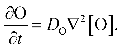
Our goal was to develop a reaction–diffusion (RD) system that would lead to the formation of a spatiotemporally stable (i.e. unchanging) gradient using DNA-based strand displacement systems. RD processes can be described by a set of partial differential equations of the form:
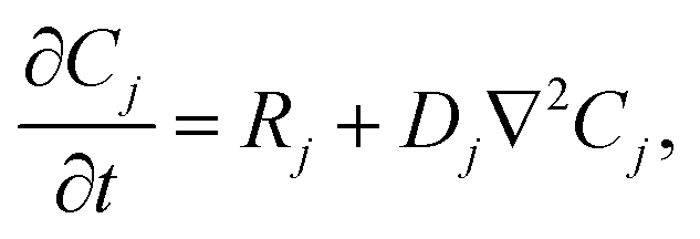 | (1) |
Our model for the generation of stable gradients is a coupled set of reactions that (1) release the species forming the gradient and (2) recapture that species. These reactions together induce the dynamics
| RO = krel − kcap[O], | (2) |
To emulate this abstract release and recapture process, we devised a set of DNA strand-displacement reactions that release and recapture an output species O, respectively:
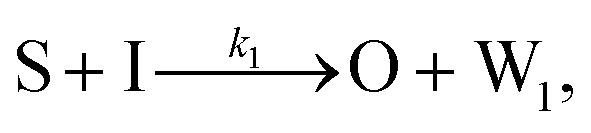 | (3) |
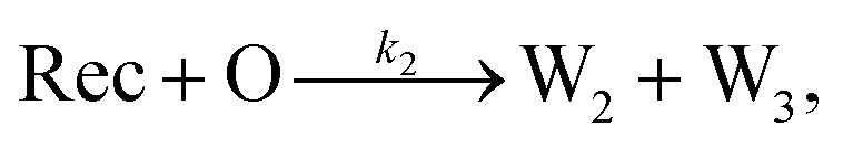 | (4) |
These opposing release and recapture reactions balance each other to form a stable point that can be used to generate stable concentration gradients. By controlling the spatial variation of the reactant concentrations and choosing the rate constants for the release and recapture reactions, a variety of gradient profiles may be created. For example, if S and I meet and release O at a single location, and Rec is present throughout the substrate, a stable gradient of O will form around the release location, which will remain stable as long as S, I and Rec are supplied to the system.
DNA strand displacement release and recapture reactions
To implement the release reaction described in eqn (3), we initially sequester the output molecule O in an inert form within the source complex S. O is rapidly released from S when it is displaced by an initiator molecule (Fig. 1A(i)). The initiator binds to the source complex via a 5 base pair toehold, which has a standard rate constant k5bp = 5 × 10⁴ (M s)−1.40 The recapture reaction in eqn (4) occurs when a recapturer complex Rec binds to O, sequestering its toehold and rendering it unable to react further (Fig. 1A(ii)). We designed the recapture reaction to occur much more slowly than the release reaction, via a strand displacement process that is initiated at a nick in the Rec dsDNA backbone, which we model with a rate constant of k2 = knick = 500 (M s)−1. Together, release and recapture processes cycle molecules of O between their released (free) and recaptured (inert) state, and can form a spatial gradient of the output strand faster than diffusion mixes the components into homogeneity. To experimentally monitor the concentration of released O, we also designed a 5bp reversible reporting reaction (eqn (5)). In this reaction, a reporter complex, Rep, which consists of a fluorescent strand f, and a quencher strand q, rapidly and reversibly reacts with output O through 5bp toeholds (Fig. 1A(iii)). | ||
| Fig. 1 Schematic of DNA strand displacement reactions and the setup of reaction diffusion systems. (A) Three strand displacement reactions generate and monitor gradients. (i) Release: the output strand is initially bound within a source complex with its toehold domain (green) sequestered in an inactive, double-stranded state. The output is released by an initiator strand via a relatively fast 5 base-pair (bp) toehold mediated reaction. (ii) Recapture: the output strand is recaptured by a recapturer complex in a relatively slow reaction. (iii) Reporting: the concentration of the output is “read” by reversibly reacting with a reporter complex whose strands have an attached fluorophore and quencher. The inset shows the structure of a waste1 complex. Green domains indicate toeholds (5bp) and the black domain indicates the “1” domain (15bp). Complementary sequences are denoted by an apostrophe (e.g., sequence 1 is fully complementary to 1′) and share the same color. Three-prime ends of the DNA strands are labeled with an arrow. The brown bump in the recapturer complex indicates a single base mismatch. (B) (i) Side-view schematic of the RD cell (x–z plane), whose exterior is formed from PDMS cast around a negative mold. The RD system inside consists of a 1% agarose hydrogel between two liquid reservoirs, each containing a solution of DNA species. An optical microscope images the cell through a glass coverslip bound to the PDMS (Methods). (ii) Top-view schematic of an RD cell (x–y plane). Inset diagrams depict initial conditions for an experiment in which a growing gradient forms: liquid reservoir 1 contains of source and reporter species, liquid reservoir 2 contains initiator and reporter species, and the hydrogel contains reporter species. | ||
Reporting:
 | (5) |
We next designed the DNA sequences, for the source, output, recapturer and reporter by starting with a set of sequences used in other strand displacement circuits.37 We added clamps to these sequences to reduce the rates of unintended “leak” reactions between the complexes.51 Such leak reactions are likely a result of fraying ends of complexes,52,53 synthesis errors54 or imperfections in complex purification, which limits the ability to design reactions to exact specifications. We include rates of these leak reactions, based on measurements and estimates,55 in our models (see ESI note SN1, ESI Fig. S1, and ESI Table ST1†).
Construction of a reaction–diffusion reaction cell and reaction monitoring
We built a reaction cell composed of three portions of approximately equal volume. The outer two portions are liquid reservoirs, with a 1% agarose hydrogel in the middle (Fig. 1B and ESI note SN2†). This set up allows us to maintain constant concentration boundary conditions at either end of the hydrogel substrate for the reactant molecules (S, I, Rec, and Rep) by manually exchanging the liquid within the reservoirs. The continuous diffusion of fresh reactants from the reservoir into the substrate, and the diffusion of waste products out of the substrate, drives the release and recapture reactions that hold the pattern of O stable in spite of diffusion. Because the agarose substrate resists non-diffusive flows, we can exchange the reaction buffer in these reservoirs repeatedly without perturbing the pattern. We measure the intensity of fluorescence using time-lapse microscopy (see Methods) and convert intensity to concentration of output using a calibration curve (ESI Fig. S2,† Methods).To design gradient patterns we built a simple, 0-parameter fit computational model that used diffusion rates for single- and double-stranded DNA and reaction rate constants for the designed reactions. We assumed that the reaction rate constants for the strand displacement were the same as those measured in free solution. Because diffusion rates can be strongly affected by the surrounding medium, we first measured the diffusion rates of single- and double-stranded DNA oligonucleotides of sizes approximately equal to those used in our reactions. We built a two-chamber agarose system where approximately 1/3 of the total length of the cell contained a 1% agarose gel which initially contained 100 nM of fluorescently labeled DNA species whose diffusion constant was to be measured.
The remaining 2/3 was composed of 1% agarose gel without DNA (Methods). We followed the spread of the species using time-lapse fluorescence microscopy (see Methods). Using standard diffusion equations, we fit a diffusion rate constant of DssDNA,23 = 115 ± 1 μm2 s−1, for single-stranded DNA or ∼75% the reported value for DNA of similar size in solution,56,57 and DdsDNA,23 = 75 ± 3 μm2 s−1 (Fig. 2). Using these values, and those assumed for the reaction rate constants, we modeled the growing gradient (ESI Fig. S3†) and the stable gradient (ESI Fig. S4†) to ensure the profiles would form as intended.
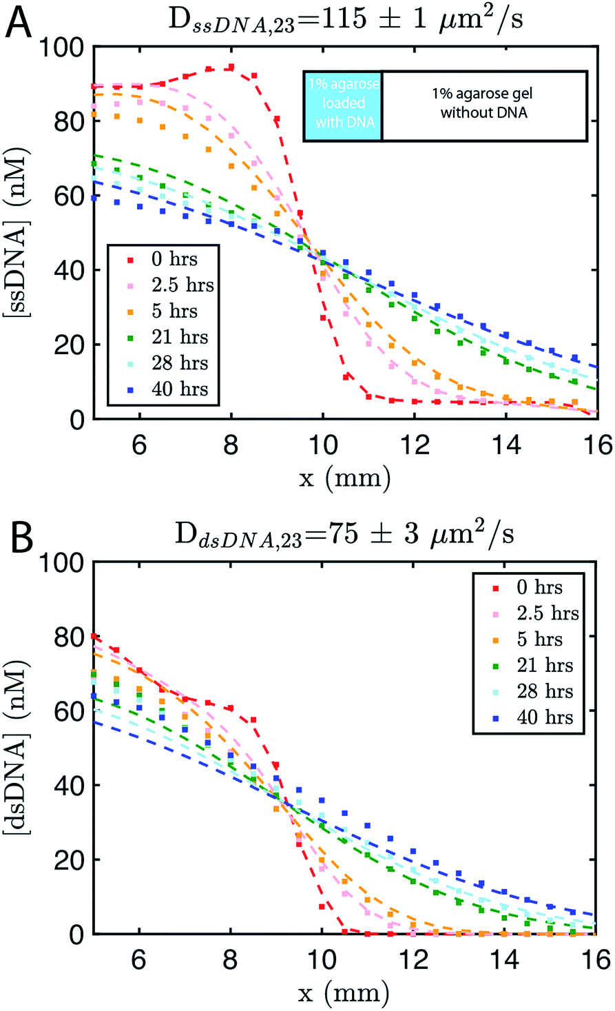 | ||
| Fig. 2 Diffusion coefficient measurement for ssDNA and dsDNA signal molecules in 1% agarose. Experimental data (square markers) and simulation of the best fit to the diffusion coefficient (dashed line) for (A) ssDNA and (B) dsDNA. The initial conditions for both experiments are shown in the inset in (A). Diffusion coefficients were fit to experimental values using a least squares fitting method; simulations show the predictions of diffusion with the best fit. 0 hours indicates the time at which imaging started, which was about 30 minutes after the fluorescently labeled DNA in agarose was added to the reaction channel. Both DNA species are 23 base pairs long. Sequences are listed in ESI note SN3.† | ||
Gradient generation by diffusion alone
We next characterized how diffusion gradients form in the absence of any release or recapture reactions. We placed a buffer solution containing 300 nM of the output in the right-hand liquid reservoir and a buffer solution with no output in the opposing reservoir. For this reactionless configuration, eqn (1) becomes
 | (6) |
Setting eqn (6) to zero gives a steady state profile as a function of position x [O](x) = [O]reservoir × (x/L), a linear concentration gradient where [O]reservoir is the concentration of O in the high concentration reservoir and L is the length of the hydrogel.
To accelerate gradient development the hydrogel was initially loaded with 150 nM of output. 200 nM of reporter was added to the reservoirs and the hydrogel. The expected linear gradient formed by about 8 hours and remained stable over at least 24 hours (Fig. 3A). The dynamics of formation were consistent with simulations that used the measured diffusion rates. We also verified that the expected linear gradient formed in response to different initial concentrations of output in the reservoirs and hydrogel, and where the total amount of DNA in the hydrogel would need to change to reach steady state (ESI Fig. S5†).
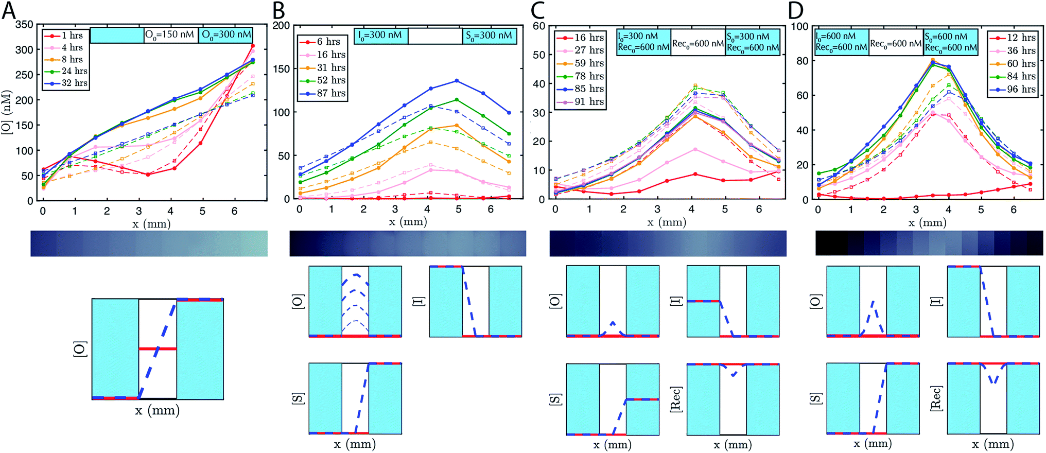 | ||
| Fig. 3 Pattern formation using DNA strand displacement reactions within an agarose hydrogel. The boundary conditions are controlled by liquid reservoirs on opposing sides of the agarose hydrogel, which contain defined concentrations of reactants and which were periodically replenished manually. Initial conditions established through loading the liquid reservoirs and the agarose hydrogel with reactants. Solid lines show the concentrations of the output species determined from micrographs (see Methods). Dotted lines are the predictions of zero parameter-fit simulations (see Methods). (A) Linear gradients, (B) “hill” gradients that grow over time and (C and D) stable hill gradients. Each gradient forms as predicted by a partial-differential equation model of reaction–diffusion. The initial concentration of the reporter complex is Rep0 = 200 nM in both the liquid reservoirs and the agarose hydrogels for all systems. The y-axis scale varies between plots. Exchange of the buffer in the reservoirs occurred in the experiment after (A) 22 hours, (B) 15 and 65 hours, (C) 24 and 52 hours, and (D) 48, 68 and 89 hours. Fluorescence micrograph depicted underneath each plot shows the state of the gradient after the longest time listed in the legend. Qualitative representation of initial conditions (red line) and concentration profile at steady state (blue dashed line) are depicted beneath plots, where the two light blue regions indicate liquid reservoirs and the white region indicates hydrogel. In the growing hill gradient, increasing time is shown as increasing linewidth. [O], [I], [S], [Rec], indicate the concentrations of output, initiator, source and recapturer, respectively. | ||
Coupled release and diffusion form growing gradients
To demonstrate that designed gradient patterns could also be formed using coupled reaction and diffusion, we loaded buffer containing 300 nM of initiator species into one reservoir and buffer containing 300 nM of source species into the opposite reservoir. Source and initiator can diffuse into the gel and react to release the output species at the point where their respective diffusion gradients meet. The height and width of the output gradient should increase over time as output continues to be released and diffuses outward (ESI Fig. S3†). Consistent with these predictions, a hill-shaped output gradient formed (Fig. 3B). The gradient of output that formed grew and broadened for at least 87 hours, with output concentrations reaching 150 nM at the central peak. To maintain the boundary conditions, the buffers in the reservoirs were replaced with fresh solution with the stated concentrations of reporter, source, and initiator about once per day. Exact times when the reservoirs were refreshed are stated in the figure captions.Stable gradients form through balanced release and recapture
To build stable gradients, we next combined the release and recapture reactions within the hydrogel. We added 300 nM of initiator species into one reservoir, 300 nM of source species into the second reservoir and 600 nM of recapturer species into both reservoirs and the hydrogel portion of the RD cell (see Methods). The high concentration of recapturer ensured that it would not be depleted significantly through interaction with the output, and that its concentration would therefore remain stable across the substrate given that the solutions in the reservoirs would be replaced about once every 24 hours. A gradient of output species emerged over 30–60 hours with higher concentrations of output near the middle of the hydrogel and lower concentrations of the edges (Fig. 3C, ESI S6†). After 60 hours, the shape of the gradient reached a shape that remained stable for an additional 30 hours. Zero parameter-fit simulations matched experiments closely: in both the simulations and experiments, gradients formed the same stable shape, and the approach to stability and the time scale at which a stable shape is achieved were also similar.Stable gradient height is controlled by boundary conditions
Higher concentrations of source and initiator on the boundary should increase the rate of output release within the hydrogel and thus increase gradient height. To test this prediction, we assembled a stable gradient using the source, initiator and recapturer species where source and initiator concentrations in their two reservoirs were 600 nM, double the concentrations used in the first experiment (Fig. 3D). The resulting gradient shape was higher as expected, and stabilized at least as quickly as the gradient formed using lower concentrations of the source and initiator, consistent with predictions, and remained stable for 30 hours.Stable reaction–diffusion in two dimensions
Having characterized the formation of 1-dimensional patterns of DNA species, our next goal was to characterize the formation of 2-dimensional patterns using a similar process. To enable control over the boundary conditions in such a way that they could be maintained through the replenishment of external reservoirs, we fabricated a square RD cell (Methods) containing two cylindrical liquid reservoirs positioned in opposite corners of the hydrogel (Fig. 4A and B). We first added source to the buffer within one reservoir and initiator molecules the liquid reservoir in the other for cells of two different sizes. The dynamics of gradient growth followed the predictions of simulations in both cases, and as expected, gradients arose more quickly in the smaller system, where the source and initiator needed to diffuse a smaller distance from their reservoir to react and release the output (ESI Fig. S7 and S8†).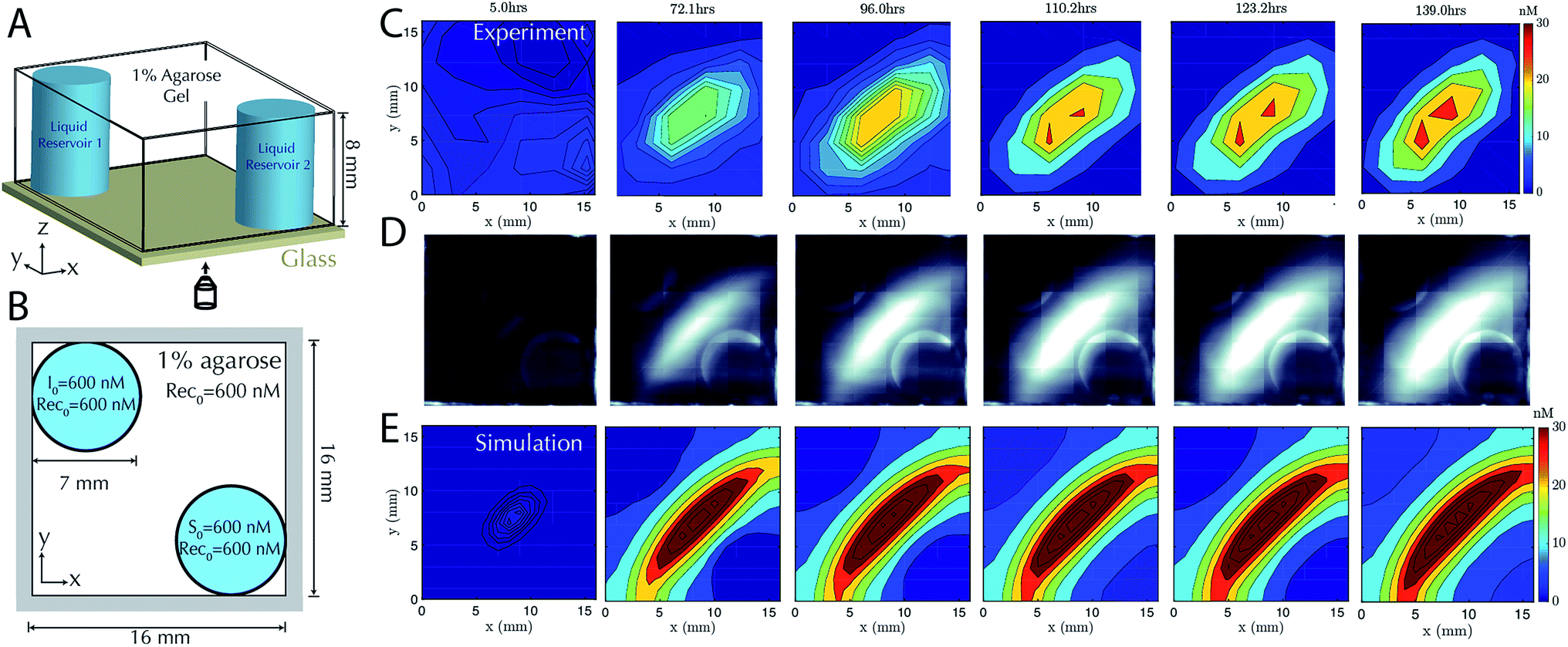 | ||
| Fig. 4 Stable two-dimensional gradient. (A) Schematic of the two-dimensional RD cell. Two cylindrical liquid reservoirs are at opposing corners of the RD cell. (B) Schematic of the top view of the 2D RD cell with initial and boundary conditions for the reactants. Reporter concentration is R0 = 200 nM in both cylindrical liquid reservoirs and the agarose gel. (C) Filled contour plots depicting the concentrations of the output at times ranging from 5 hours (left) to 139 hours (right). The stable gradient within the hydrogel takes approximately 110 hours to develop and is stable until the experiment was terminated at 139 hours. Exchange of the buffer in the reservoirs occurred in the experiment after 22, 48, 71, 93 and 116 hours. (D) Corresponding fluorescence micrographs (see Methods). (E) Filled contour plots depicting the simulated values of output concentration profile from 5 to 139 hours. | ||
To test that stable, two-dimensional gradients of output concentration could form, we loaded one reservoir with 600 nM of source complex and the other with 600 nM of initiator species, with 600 nM of recapturer in both reservoirs and in the hydrogel. The gradient produced a peak concentration of about 30 nM in 110 hours, which was stable for a further 29 hours (Fig. 4C–E). Simulation generally captured the behavior of the stable two-dimensional gradient, although slightly higher peak amplitudes were predicted. We expect this difference could result from non-uniform hydrogel composition along the reservoir interface, which can reduce local diffusion rates and thus reduce the flux of reactants into the hydrogel, while the model assumes a homogeneous gel. These variations could not be captured in our 0-parameter fit simulations.
DNA systems with different sequences form multiplexed gradient patterns
DNA strand-displacement systems are of interest as a substrate for programming RD processes not only because the reaction rates of the components can be controlled, but also because multiple reaction processes involving different sequences can operate together with minimal crosstalk or as coupled reaction processes to produce more complex patterns. To verify that such scaling is feasible, we developed two non-interacting (i.e., orthogonal) sets of reactions for the release, recapture and reporting of output species and tested whether they could be executed in parallel. We refer to the initial set of complexes as the 1–2 system and the new set of complexes as the 3–4 system, after the numbered domains within each system. We used NUPACK58 to determine the secondary structures that could form between the strands of the complexes and ensured that no more than 1% of the complexes were predicted to have structures other than those that were designed at equilibrium. For the reporter in the 1–2 system, a 3′ Iowa Black FQ quenches 5′ fluorescein (FAM) fluorophore (Fig. 1A(ii)) and for the 3–4 system, a 3′ Iowa Black RQ quenches 5′ Texas Red® fluorophore (see sequence information in ESI note SN3†).To form stable, multiplexed gradients, we loaded one reservoir in a 1-dimensional RD cell with 300 nM of each initiator, the other reservoir with 300 nM of each source and in each liquid reservoir and hydrogel loaded 300 nM recapturer for each system (Fig. 5A). The reporter complexes for each system were presented at 200 nM in both the hydrogel and reservoirs. Both gradients achieved the expected shape and approached a final stable state, consistent with the predictions of simulations (Fig. 5B and C). Each gradient took approximately the same amount of time to form, but the 1–2 gradient had a maximum concentration of about 60 nM, whereas the 3–4 gradient had a maximum concentration of about 40 nM. The 3–4 gradient was not yet stable after about 85–95 hours with increases in output concentration on the order of a few percent per hour over 88–94 hours, whereas the 1–2 gradient appeared to have achieved a stable configuration by this time. Sequence-specific differences in reaction rate constants can vary by up to an order of magnitude40 in strand displacement processes. The differences in the precise maximum concentrations and time constants between the two systems are consistent with such differences in reaction rate constants. In the future, modeling software that takes sequence data into consideration could be used to control this variation.59
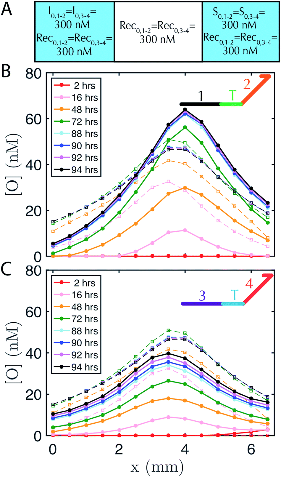 | ||
| Fig. 5 Two stable, overlapping gradients of output species can be formed in one hydrogel by two non-interacting (orthogonal) sets of reactants (denoted 1–2 and 3–4 for their recognition domains, see inset cartoon diagrams of output species in B–C). (A) Initial conditions of reactants in the 1–2 and 3–4 systems in the liquid reservoirs and hydrogel. Initial reporter concentrations are R0,1–2 = R0,3–4 = 200 nM in both liquid reservoirs and the agarose hydrogel and are not depicted for clarity. Concentration profiles for the output strands from the (B) 1–2 system and (C) 3–4 system. The reporter in the 1–2 system has a FAM fluorophore, whereas the reporter complex in the 3–4 system has a Texas-Red fluorophore, so the respective fluorescence profiles (which are then converted to concentration profiles) were measured using non-overlapping filters for FAM and Texas Red channel (see Methods). Buffer in the reservoirs was exchanged after 48 hours. | ||
Conclusion
In this work we have shown how DNA strand displacement reactions operating far from equilibrium can be used to engineer stable reaction–diffusion gradients. Such patterns evolve over time in a predictable fashion. Much of the vast potential parameter space for such systems remains to be explored, including altering the reaction rate constants (e.g., changing the length of the toehold domain39,40) and/or the diffusion rates (e.g., by introducing hydrodynamic drag56 or by altering length of the DNA components57), which could also serve to sharpen the spatial resolution. External reservoirs allow us to refuel the system, enabling far-from-equilibrium patterns to be sustained for at least tens of hours, and no fundamental time limit for such stability was observed. It may be possible to speed gradient formation by increasing the hydrogel pore size by using a lower percentage agarose, or miniaturizing the size scale of the RD cell to a microfluidic device. Device miniaturization could also improve the spatial resolution, which is currently on the order of hundreds of μm. To build more sophisticated systems, it will also be important to reduce undesirable leak reactions between reactants.59–62The stable release and recapture reaction mechanism could enable the implementation of self-regenerating patterns, which return to a target stable structure after they are perturbed by some external stimulus (e.g., a high concentration of a reactant in a strand displacement system, or a transient flow). To characterize the capacity for regeneration, methods for reliable perturbation are required, such as through the use of light-driven release. Finally, downstream Boolean logic operations could facilitate the generation of patterns with arbitrarily complex shape,49 dynamics,50 and functional responses to changing environmental conditions. The use of biocompatible reactants, hydrogels and strand-displacement reactions, which can operate under a variety of conditions, mean that one could envision interacting with biological systems63 and other downstream processes.64,65
Materials and methods
DNA complex preparation
All DNA strands were ordered from Integrated DNA Technologies (IDT) with standard desalting except fluorescently modified strands, which were HPLC purified. Complexes were formed by mixing the component strands at equimolar ratio in TAE Mg2+ (40 mM Tris–acetate, 1 mM EDTA buffer containing 12.5 mM magnesium acetate) and then placed in an Eppendorf Mastercycler PCR, where the strands were annealed. Annealing consisted of holding the temperature at 95 °C for 5 minutes and then cooling the solution to 25 °C at a rate of −1 °C per minute. After annealing, each complex was purified by polyacrylamide gel electrophoresis (PAGE) using a 10% polyacrylamide run at 120 V for 90 minutes at 4 °C (see ref. 55 for more details). The bands corresponding to the complexes were identified using UV-shadowing at a wavelength of 254 nm. The band was then diced, combined with TAE Mg2+ buffer into a tube and shaken on a vortexer for about 12 hours, to promote complex migration into the aqueous solution. The solution was then centrifuged for 5 minutes at 3000 × g and the supernatant removed, which was repeated twice to ensure separation of gel from solution. Concentration measurements were obtained using an Eppendorf Biophotometer. The extinction coefficient, ε, of a complex was approximated by the formula: ε = εtop + εbottom − 3200NAT − 2000NGC, where εtop and εbottom are the extinction coefficients of the two strands that comprise the complex and NAT and NGC are the number of hybridized A–T and G–C base pairs in the complex.66Hydrogel preparation
Agarose gels with DNA complexes were prepared by mixing liquid agarose and complexes and then cooling the gels in devices to set. We prepared 1% agarose hydrogel (1 g/100 mL) in TAE Mg2+ and left it to cool to 40 °C, after which we transferred the agarose solution to a glove box with PID fan temperature control (Coy Labs) set to 40 °C. Buffers, DNA complex solutions, pipettes and pipette tips were left in the glove box at least 30 minutes prior to sample preparation to achieve thermal equilibrium. The agarose was mixed with the DNA solution (typically with reporter and any other complex that was required for the experiment) and the resulting mixed was transferred to the device in the desired well(s). After all wells were patterned, a piece of scotch tape was adhered to the PDMS to seal the wells and the device was transferred to the refrigerator at 4 °C for 15 minutes to set the gels. We found that 40 °C was hot enough for the agarose to remain a liquid, but NuPack's58 compute melt function predicts 40 °C is well below the melting temperature of our DNA complexes. The reservoir solutions were added after the gel had been cooled to room temperature and all results were collected at room temperature. Glass coverslips were placed on top of the device to mitigate evaporation from the calibration and reaction wells during the reaction–diffusion process (see more discussion on evaporation in ESI Fig. S9†).Reaction monitoring
The reaction was monitored using time-lapse fluorescence microscopy on either an IX73 or IX71 (Olympus) optical microscope. Image sets were obtained every ∼30 minutes with an exposure of 50–150 ms using a 4×, 10× or 20× objective (Olympus) and were captured by an infinity 3 CCD camera (Lumenera Corporation) in non-overlapping FAM and Texas-Red channels (Chroma) on the IX73, or an iXon3 cooled EMCCD camera (Andor) using a FAM channel (Chroma) on the IX71. The center of the focal plane for each experiment was approximately 1 to 4 mm in the z direction above the glass slide, as determined by the minimum width of the light beam in the direction perpendicular to the optical axis. We post-processed the images via binning and dark frame correction to compress the data and eliminate some of the optical artifacts, respectively (ESI Fig. S10†).Diffusion coefficient measurement
Diffusion coefficients were fit to experimental values using a least squares fitting method; simulations show the predictions of diffusion with the best fit. The system consisted of a 1% agarose gel that initially contained no DNA as shown and was cast and left at room temperature to gel for approximately 30 minutes prior to adding the gel with DNA. After this set time, the remaining ∼1/3 of the reaction cell was loaded with reaction buffer that contained ∼75 to 100 nM of fluorescently labeled DNA. 0 hours indicates the time at which imaging started, which was about 30 minutes after the fluorescently labelled DNA in agarose was added to the reaction channel. Starting concentration profile used in the simulation was taken from the initial experimental concentration profile (i.e., at 0 hours).Liquid reservoir exchange
Contents of the liquid reservoirs are removed with a transfer pipette and replaced with fresh reaction buffer (prepared <10 minutes prior to exchange). Reservoir solution exchanges were performed approximately every 24 hours and are stated in the figure captions.Simulations
To perform the simulations, we used COMSOL Multiphysics® Version 4.4 and LiveLink™ for MATLAB. Models of reaction–diffusion channels were built using COMSOL with the “Transport of Diluted Species” physics. All hydrogel-PDMS and liquid-PDMS boundaries were simulated with no flux boundary conditions. Simulations were run using scripts written in MATLAB using COMSOL Java API commands, which is how we defined simulation parameters such as reactions and their rate constants, diffusion constants, initial conditions and boundary conditions, mesh size and buffer exchange times. Buffer exchange of the liquid reservoirs occurred in simulations at the same time points as those in our experiments. Buffer exchange consisted of replacing each liquid reservoir with their initial contents (unreacted species) while the concentration profiles of species in the hydrogel remained unchanged and to simulate a particular process, the specific timing of buffer exchange from that experiment was included in the simulation. Diffusion coefficients for the hydrogel domain were set to measured values. Diffusion coefficients in the liquid reservoirs were all equal and had a value of 150 μm2 s−1.57,67 Reaction rate constants for intended reactions were set according to estimated values in solution (see ref. 40) and reaction rate constants for leak reactions were estimated (see ESI Fig. S1†). COMSOL models and MATLAB scripts are available upon request.Acknowledgements
The authors would like to thank Deepak Agrawal, Angelo Cangialosi, Qi Huang, Abdul M. Mohammed, and Samuel Schaffter for helpful discussions, and Markela Ibo for her assistance with fabrication techniques for reaction–diffusion devices. This work was supported by DOE BES grant 90068952 (for support of J. F. and J. Z. and some materials and supplies) and NSF CCF grant 1161941 to R. S. (for support of D. S. and some early work).References
- M. Akam, Development, 1987, 101, 1–22 CAS.
- J. B. A. Green and J. Sharpe, Development, 2015, 142, 1203–1211 CrossRef CAS PubMed.
- P. Bastiaens, M. Caudron, P. Niethammer and E. Karsenti, Trends Cell Biol., 2006, 16, 125–134 CrossRef CAS PubMed.
- B. N. Kholodenko, FEBS Lett., 2009, 583, 4006–4012 CrossRef CAS PubMed.
- N. L. Jeon, H. Baskaran, S. K. W. Dertinger, G. M. Whitesides, L. Van de Water and M. Toner, Nat. Biotechnol., 2002, 20, 826–830 CrossRef CAS PubMed.
- G. S. Jeong, S. Han, Y. Shin, G. H. Kwon, R. D. Kamm, S. H. Lee and S. Chung, Anal. Chem., 2011, 83, 8454–8459 CrossRef CAS PubMed.
- B. G. Chung, L. A. Flanagan, S. W. Rhee, P. H. Schwartz, A. P. Lee, E. S. Monuki and N. L. Jeon, Lab Chip, 2005, 5, 401–406 RSC.
- S. K. W. Dertinger, X. Y. Jiang, Z. Y. Li, V. N. Murthy and G. M. Whitesides, Proc. Natl. Acad. Sci. U. S. A., 2002, 99, 12542–12547 CrossRef CAS PubMed.
- Y. Shin, S. Han, J. S. Jeon, K. Yamamoto, I. K. Zervantonakis, R. Sudo, R. D. Kamm and S. Chung, Nat. Protoc., 2012, 7, 1247–1259 CrossRef CAS PubMed.
- C. A. DeForest, B. D. Polizzotti and K. S. Anseth, Nat. Mater., 2009, 8, 659–664 CrossRef CAS PubMed.
- E. Karzbrun, A. M. Tayar, V. Noireaux and R. H. Bar-Ziv, Science, 2014, 345, 829–832 CrossRef CAS PubMed.
- J. K. He, Y. A. Du, J. L. Villa-Uribe, C. M. Hwang, D. C. Li and A. Khademhosseini, Adv. Funct. Mater., 2010, 20, 131–137 CrossRef CAS PubMed.
- V. Sourjik and N. S. Wingreen, Curr. Opin. Cell Biol., 2012, 24, 262–268 CrossRef CAS PubMed.
- L. D. Zarzar, Q. H. Liu, X. M. He, Y. H. Hu, Z. G. Suo and J. Aizenberg, Soft Matter, 2012, 8, 8289–8293 RSC.
- M. Mayer, J. Yang, I. Gitlin, D. H. Gracias and G. M. Whitesides, Proteomics, 2004, 4, 2366–2376 CrossRef CAS PubMed.
- S. H. Lee, J. J. Moon and J. L. West, Biomaterials, 2008, 29, 2962–2968 CrossRef CAS PubMed.
- M. S. Hahn, J. S. Miller and J. L. West, Adv. Mater., 2006, 18, 2679–2684 CrossRef CAS.
- S. K. W. Dertinger, D. T. Chiu, N. L. Jeon and G. M. Whitesides, Anal. Chem., 2001, 73, 1240–1246 CrossRef CAS.
- J. Atencia, J. Morrow and L. E. Locascio, Lab Chip, 2009, 9, 2707–2714 RSC.
- F. Lin, W. Saadi, S. W. Rhee, S. J. Wang, S. Mittal and N. L. Jeon, Lab Chip, 2004, 4, 164–167 RSC.
- J. P. Diao, L. Young, S. Kim, E. A. Fogarty, S. M. Heilman, P. Zhou, M. L. Shuler, M. M. Wu and M. P. DeLisa, Lab Chip, 2006, 6, 381–388 RSC.
- F. Sagues and I. R. Epstein, Dalton Trans., 2003, 1201–1217, 10.1039/b210932h.
- V. K. Vanag and I. R. Epstein, Chaos, 2008, 18, 026107 CrossRef PubMed.
- S. N. Semenov, A. J. Markvoort, W. B. L. Gevers, A. Piruska, T. F. A. de Greef and W. T. S. Huck, Biophys. J., 2013, 105, 1057–1066 CrossRef CAS PubMed.
- M. Loose, E. Fischer-Friedrich, J. Ries, K. Kruse and P. Schwille, Science, 2008, 320, 789–792 CrossRef CAS PubMed.
- D. G. Miguez, V. K. Vanag and I. R. Epstein, Proc. Natl. Acad. Sci. U. S. A., 2007, 104, 6992–6997 CrossRef CAS PubMed.
- E. Jee, T. Bansagi, A. F. Taylor and J. A. Pojman, Angew. Chem., Int. Ed., 2016, 55, 2127–2131 CrossRef CAS PubMed.
- M. M. Wrobel, T. Bansagi, S. K. Scott, A. F. Taylor, C. O. Bounds, A. Carranza and J. A. Pojman, Biophys. J., 2014, 106, 1548 CrossRef CAS.
- S. N. Semenov, A. J. Markvoort, T. F. A. de Greef and W. T. S. Huck, Angew. Chem., Int. Ed., 2014, 53, 8066–8069 CrossRef CAS PubMed.
- M. Isalan, C. Lemerle and L. Serrano, PLoS Biol., 2005, 3, 488–496 CAS.
- A. Padirac, T. Fujii, A. Estevez-Torres and Y. Rondelez, J. Am. Chem. Soc., 2013, 135, 14586–14592 CrossRef CAS PubMed.
- A. S. Zadorin, Y. Rondelez, J. C. Galas and A. Estevez-Torres, Phys. Rev. Lett., 2015, 114, 068301 CrossRef CAS PubMed.
- T. Bansagi, V. K. Vanag and I. R. Epstein, Science, 2011, 331, 1309–1312 CrossRef CAS PubMed.
- I. R. Epstein and B. Xu, Nat. Nanotechnol., 2016, 11, 312–319 CrossRef CAS PubMed.
- H. W. H. van Roekel, B. J. H. M. Rosier, L. H. H. Meijer, P. A. J. Hilbers, A. J. Markvoort, W. T. S. Huck and T. F. A. de Greef, Chem. Soc. Rev., 2015, 44, 7465–7483 RSC.
- G. Seelig, D. Soloveichik, D. Y. Zhang and E. Winfree, Science, 2006, 314, 1585–1588 CrossRef CAS PubMed.
- L. Qian and E. Winfree, Science, 2011, 332, 1196–1201 CrossRef CAS PubMed.
- Y. J. Chen, B. Groves, R. A. Muscat and G. Seelig, Nat. Nanotechnol., 2015, 10, 748–760 CrossRef CAS PubMed.
- D. Y. Zhang and G. Seelig, Nat. Chem., 2011, 3, 103–113 CrossRef CAS PubMed.
- D. Y. Zhang and E. Winfree, J. Am. Chem. Soc., 2009, 131, 17303–17314 CrossRef CAS PubMed.
- D. Y. Zhang, A. J. Turberfield, B. Yurke and E. Winfree, Science, 2007, 318, 1121–1125 CrossRef CAS PubMed.
- Y. J. Chen, N. Dalchau, N. Srinivas, A. Phillips, L. Cardelli, D. Soloveichik and G. Seelig, Nat. Nanotechnol., 2013, 8, 755–762 CrossRef CAS PubMed.
- D. Soloveichik, G. Seelig and E. Winfree, Proc. Natl. Acad. Sci. U. S. A., 2010, 107, 5393–5398 CrossRef CAS PubMed.
- L. Qian and E. Winfree, J. R. Soc., Interface, 2011, 8, 1281–1297 CrossRef CAS PubMed.
- D. Y. Duose, R. M. Schweller, J. Zimak, A. R. Rogers, W. N. Hittelman and M. R. Diehl, Nucleic Acids Res., 2012, 40, 3289–3298 CrossRef CAS PubMed.
- J. Hemphill and A. Deiters, J. Am. Chem. Soc., 2013, 135, 10512–10518 CrossRef CAS PubMed.
- S. M. Chirieleison, P. B. Allen, Z. B. Simpson, A. D. Ellington and X. Chen, Nat. Chem., 2013, 5, 1000–1005 CrossRef CAS PubMed.
- P. B. Allen, X. Chen and A. D. Ellington, Molecules, 2012, 17, 13390–13402 CrossRef CAS PubMed.
- D. Scalise and R. Schulman, Technology, 2014, 2, 55–66 CrossRef.
- D. Scalise and R. Schulman, Nat. Comput., 2016, 15(2), 197–214 CrossRef CAS.
- P. Yin, H. M. T. Choi, C. R. Calvert and N. A. Pierce, Nature, 2008, 451, 318–322 CrossRef CAS PubMed.
- J. L. Leroy, M. Kochoyan, T. Huynhdinh and M. Gueron, J. Mol. Biol., 1988, 200, 223–238 CrossRef CAS PubMed.
- S. Nonin, J. L. Leroy and M. Gueron, Biochemistry, 1995, 34, 10652–10659 CrossRef CAS PubMed.
- K. H. Hecker and R. L. Rill, BioTechniques, 1998, 24, 256–260 CAS.
- J. Fern, D. Scalise, A. Cangialosi, D. Howie, L. Potters and R. Schulman, ACS Synth. Biol., 2016, 6(2), 190–193 CrossRef PubMed.
- S. Doose, H. Barsch and M. Sauer, Biophys. J., 2007, 93, 1224–1234 CrossRef CAS PubMed.
- G. L. Lukacs, P. Haggie, O. Seksek, D. Lechardeur, N. Freedman and A. S. Verkman, J. Biol. Chem., 2000, 275, 1625–1629 CrossRef CAS PubMed.
- J. N. Zadeh, C. D. Steenberg, J. S. Bois, B. R. Wolfe, M. B. Pierce, A. R. Khan, R. M. Dirks and N. A. Pierce, J. Comput. Chem., 2011, 32, 170–173 CrossRef CAS PubMed.
- J. M. Schaeffer, C. Thachuk and E. Winfree, in DNA Computing and Molecular Programming: 21st International Conference, DNA 21, Boston and Cambridge, MA, USA, August 17-21, 2015, Proceedings, ed. A. Phillips and P. Yin, Springer International Publishing, Cham, 2015, pp. 194–211, DOI:10.1007/978-3-319-21999-8_13.
- C. Thachuk, E. Winfree and D. Soloveichik, International Workshop on DNA-Based Computers, 2015 Search PubMed.
- X. Olson, S. Kotani, J. E. Padilla, N. Hallström, S. Goltry, J. Lee, B. Yurke, W. L. Hughes and E. Graugnard, ACS Synth. Biol., 2016, 6(1), 84–93 CrossRef PubMed.
- C. Grun, J. Werfel, D. Y. Zhang and P. Yin, J. R. Soc., Interface, 2015, 12, 0580 CrossRef PubMed.
- M. X. You, G. Z. Zhu, T. Chen, M. J. Donovan and W. H. Tan, J. Am. Chem. Soc., 2015, 137, 667–674 CrossRef CAS PubMed.
- E. Franco, E. Friedrichs, J. Kim, R. Jungmann, R. Murray, E. Winfree and F. C. Simmel, Proc. Natl. Acad. Sci. U. S. A., 2011, 108, E784–E793 CrossRef CAS PubMed.
- I. R. Epstein and B. Xu, Nat. Nanotechnol., 2016, 11, 312–319 CrossRef CAS PubMed.
- J. D. Puglisi and I. Tinoco Jr, Methods Enzymol., 1989, 180, 304–325 CAS.
- E. Stellwagen, Y. J. Lu and N. C. Stellwagen, Biochemistry, 2003, 42, 11745–11750 CrossRef CAS PubMed.
Footnote |
| † Electronic supplementary information (ESI) available. See DOI: 10.1039/c7ra00824d |
| This journal is © The Royal Society of Chemistry 2017 |