 Open Access Article
Creative Commons Attribution 3.0 Unported Licence
Characterization of self-sealing MAO ceramic coatings with green or black color on an Al alloy
Wei Yanga,
Dapeng Xua,
Jian Chena,
Jiangnan Liua and
Bailing Jiangb
aSchool of Materials Science and Chemical Engineering, Xi'an Technological University, Xi'an 710032, China. E-mail: yangwei_smx@163.com; chenjian@xatu.edu.cn; Fax: +86 029 86173324; Tel: +86 029 86173324
bSchool of Materials Science and Engineering, Nanjing Tech University, Nanjing 211816, China
First published on 5th January 2017
Abstract
Micro arc oxidation (MAO) coatings with green or black color were obtained on a 6061 Al alloy in a new Cr-containing electrolyte system. Compared to the white coatings obtained with traditional electrolytes, this black coating has the characteristics of self-sealing pores and different chemical compositions. The microstructure and composition of the different coatings were comparatively studied by field-emission scanning electron microscopy (FESEM), energy dispersive X-ray spectrometry (EDS) and X-ray photoelectron spectroscopy (XPS), respectively. The mechanical property, tribological behavior and corrosion resistance of the MAO coatings were systematically investigated using nano-indentation, tribological tester and electrochemical corrosion tests. The results indicated that the green MAO coating with a porous structure had Cr2O3 distributed into the Al2O3 ceramic coating with a little of K2Cr2O7 addition into the base solution, and the black MAO coating with a self-sealing microstructure contained Cr2O3 and CrO3 with a large amount of K2Cr2O7 addition into the base solution. The hardness values of the MAO coatings with an increase of Cr at% increased first and then decreased due to the compact structure and different compositions of the MAO coatings. Compared with the other MAO coatings, the self-sealing black MAO coating with a high Cr content showed greatly improved wear resistance and corrosion resistance for its special microstructure. Furthermore, the formation mechanism of these MAO coatings with Cr addition has been revealed and the relationship between microstructure and properties has been discussed.
1. Introduction
Aluminum alloys are widely used in engineering and aerospace applications due to their characteristics of small density, good plasticity, high specific strength and good heat conductivity.1–3 However, to a large extent, the high chemical activity, low hardness, poor wear resistance and corrosion resistance of aluminum alloys limit their wide range of applications.4,5 Therefore, it is necessary to deal with the surface of aluminum alloys for improving their performance.6–8 Micro arc oxidation (MAO) technology, another widely used name of plasma electrolytic oxidation (PEO), is a promising method in the surface treatment of aluminum alloys as it can effectively improve aluminum alloys' hardness, wear resistance and corrosion resistance.9–14 In addition, the coatings with different colors on aluminum alloys are required in the decoration and optical fields. Currently, variety colors of MAO coatings on Al substrates can be obtained from white to black, and the formation mechanism of black MAO coatings has been revealed.15,16 It is known that the black MAO coating can be prepared in the solution with NH4VO3 addition, but NH4VO3 is easy to decompose, which is difficult to stably fabricate the black MAO coating. Also this MAO coating demonstrated deteriorated performances, which limited its implication. Meanwhile, Zhao17 reported that NH4VO3 as colorant could be used to prepare green coating on aluminum alloy using the same method of black MAO coating. This green MAO coating would be used in the military field.Furthermore, self-sealing MAO coatings have been prepared on magnesium alloys by adding K2ZrF6 or K2TiF6 into the base solutions for the function of transition metal elements (such as Zr and Ti) and it is found that the corrosion resistance of these self-sealing coatings has been significantly improved compared with that of the traditional MAO coatings.18–21 But self-sealing MAO coatings with excellent properties on aluminium alloys were not studied. It is speculated that a self-sealing MAO coating might be also obtained on aluminium alloys by adding potassium dichromate (K2Cr2O7) into a base solution for the function of transition metal element Cr, which was beneficial to seal pores and improve its properties. Besides, it is also known that chromium oxide (such as Cr2O3 and CrO3) has excellent toughness and can display green color (Cr2O3) and black color (Cr2O3 and CrO3). So, it is expected that Al2O3 composite coatings distributed with chromium oxide could be prepared in different colors. Certainly, the hexavalent chromium is toxic, which is widely used in electroplating process.22 But the amount of hexavalent chromium from K2Cr2O7 (12 g L−1) during the MAO process in this paper was much lower than that of the electroplating process (hundreds of g L−1). Furthermore, the MAO electrolyte can be used in a long-term recycle and it is useful for reducing pollution.
In this paper, different amount of K2Cr2O7 as colorant was added into an alkaline (NaPO3)6–Na2SiO3–KOH–KF base solution to prepare MAO coatings with different Cr content and improve their performance. The microstructure and properties of these MAO coatings were studied systematically. Furthermore, the formation process of MAO coatings with different colors and evolutions of their microstructure and properties had been also discussed.
2. Experimental details
6061 aluminum alloy substrate discs (Φ 20 mm × 6 mm) were mechanically polished with 600#, 1000#, and 1500# abrasive papers, respectively, and then it was followed by ultrasonic cleaning in acetone for 20 min. JHMAO-60 micro arc oxidation equipment (made by Xi'an University of Technology, China) was used to prepare the MAO coatings on Al alloy surface. The constant voltage mode was selected for MAO treatment and 460 V was predefined. The MAO parameters were as follows: frequency 400 Hz, duty cycle 10% and time 15 min. The base solution used for MAO was composed of an aqueous solution of sodium hexametaphosphate ((NaPO3)6, 45 g L−1), sodium silicate (Na2SiO3 5 g L−1), potassium hydroxide (KOH, 1.2 g L−1) and potassium fluoride (KF, 3 g L−1). K2Cr2O7 as colorant was added into the base solution in concentrations of 0 g L−1, 2.5 g L−1, 5.0 g L−1, 8.0 g L−1 and 12 g L−1 for the preparation of Cr-incorporated MAO coatings. The solution temperature was kept below 40 °C. In the further text, we would use the terms “0 g L−1 K2Cr2O7, 2.5 g L−1 K2Cr2O7, 5.0 g L−1 K2Cr2O7, 8.0 g L−1 K2Cr2O7, 12 g L−1 K2Cr2O7” to denote the five MAO coatings with Cr doping, as the additions of K2Cr2O7 were 0 g L−1, 2.5 g L−1, 5.0 g L−1, 8.0 g L−1 and 12 g L−1, respectively. As shown in Fig. 1, the color of MAO coatings has a tendency to become dark with the increase of K2Cr2O7 addition. A green MAO coating was obtained in the solution with the concentration of 5.0 g L−1 K2Cr2O7 and a black MAO coating was obtained in the solution with 12 g L−1 K2Cr2O7 addition. The thickness of the coating was measured using the TT230 eddy-current coating-thickness measurement gauge. The thickness of the MAO coatings was approximately 10–12 μm. | ||
| Fig. 1 Macrograph of 6061 Al alloy substrate or treated by MAO in different electrolytes with different K2Cr2O7 additions, 0 g L−1, 2.5 g L−1, 5.0 g L−1, 8.0 g L−1, 12 g L−1. | ||
Field-emission scanning electron microscopy (FE-SEM, S-4800, Hitachi, Japan) an energy dispersive spectroscope (EDS) attachment operated at an acceleration potential of 20 kV were used for morphological characterization of the MAO coatings. The X-ray generator was operated at 40 kV and 40 mA. An X-ray photoelectron spectroscopy (XPS) with Al (mono) Kα irradiation at pass energy of 200 eV was used to characterize the chemical bonds of the films. The binding energies were referenced to the C 1s line at 284.6 eV. Microhardness measurements were conducted by Nano indentation using the nano-indentation technique in a continuous stiffness measurement (CSM) mode (NANO, G200, MTS, America) and four indentations were made in each sample. The sliding friction and wear behavior were evaluated in the ball-on-plate sliding tests against WC–Co ball (diameter of 6 mm) on a UMT-3 tribometer (CETR, USA) at room temperature with a relative humidity of 65% under the dry sliding conditions. The sliding mode was reciprocating with the track length of 2.5 mm at 5 Hz for 600 s and the applied normal load was 4 N. After friction tests, the wear tracks were measured by a surface profiler (Alpha-StepIQ, KLA-Tencor Corporation, USA) and SEM. Then, the average values of the cross-sectional area and the depth of the track were calculated from the data obtained. Therefore, the losses of the materials cross-sectional area (S) could be obtained and the loss of the sample volume was calculated from the formula: ΔVsample = Sd (mm3), where d was the length of the wear track (mm). The wear rate of the sample was calculated by normalizing the volume loss ΔVsample in the course of the test to the total path N (m) and the applied load P (N): I = ΔVsample/(NP). The compositions of the wear tracks were analyzed with EDS. The corrosion resistance of the MAO coatings formed in the electrolytes with different concentrations of K2Cr2O7 was tested by Autolab Pgstat302 electrochemical system in 3.5% NaCl solution under room temperature using electrochemical potentiodynamic polarization. The specimen with the surface area of 0.785 cm2 was exposed in the solution as the working electrode. The platinum sheet was auxiliary electrode, and the saturated calomel electrode was the reference electrode. The scanning speed was 2 mV s−1. Then a 64 bit system-zview software was used to fit and calculate the corrosion current density (Ic) and corrosion potential (Ec) values by Tafel polarization curve and the accuracy of the obtained dates (Ic and Ec) was 0.01.
3. Results and discussion
3.1 Coating characteristics
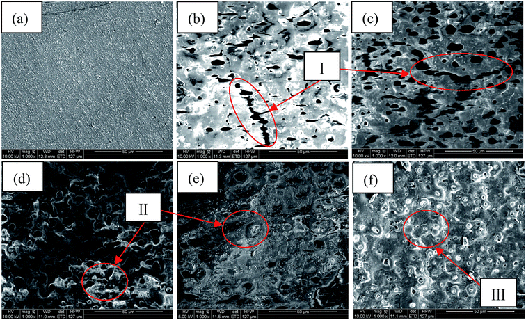
Fig. 2 shows the surface morphologies of Al alloy substrate and the MAO coated samples with K2Cr2O7 additions. It was found that the substrate surface was smooth after polishing, shown in Fig. 2(a). With increase of the concentration of K2Cr2O7, the porous surface characteristics of MAO coatings were shown in Fig. 2(b)–(f). A large number of pores were distributed in the MAO coatings prepared in 0 g L−1 K2Cr2O7 and 2.5 g L−1 K2Cr2O7 solutions and also some cracks were obviously observed (region I), which were resulted from the thermal stress due to the rapid solidification of the molten oxide in the relatively cool electrolyte (below 40 °C). It was known that arc discharge region with very high temperatures suddenly encountering low temperature solution could result in the surface rupture of ceramic coating.13 With the further increase of concentration of K2Cr2O7, from 5 g L−1 to 8 g L−1, the cracks were disappeared and the number of pores obviously decreased on the coating surface (region II), shown in Fig. 2(d) and (e). Especially, as the concentration of K2Cr2O7 was 12 g L−1, the pores on coating surface were almost disappeared (Fig. 2(f)). It has been proved that the spark discharge occurs first at weak and the solute ions can be preferentially concentrated in these locations (such as discharge hole) during the self-sealing process. Also, Cr from solute ion could be changed into its oxide under high temperature. As a result, a self-sealing effect changed obvious with the increase of K2Cr2O7 into the solution. Namely, the K2Cr2O7 colorant was beneficial to sealing the pores of the MAO coating. This self-sealing microstructure was similar with the literatures.20,23Table 1 shows the EDS results of the Al alloy substrate and the MAO coatings with or without K2Cr2O7 addition. It was found that Al alloy substrate mainly contained Al, Si and O elements. Al and Si were from the substrate. O element was due to the oxidation of surface grinding. The MAO coating prepared in the base solution mainly contained Al and O elements, which indicated that the ceramic coating was mainly composed of aluminum oxide. More important was that Al concentration for the sample with 8.0 g L−1 K2Cr2O7 was increased compared with the samples with 2.5, 5.0 or 12 g L−1 K2Cr2O7. It was known that the formation of MAO coating was a process that the surface atom of Al substrate changed into its oxide under high temperature and high pressure, and a little of Al atom could not be transformed into aluminum oxide in local area. As a result, the EDS analysis in this local area presented high concentrations of Al and Cr elements in this MAO coating with a low concentration of O element. Si and P elements from the electrolyte were also found in the ceramic coating and it illustrated that the solute ions were involved in the formation of MAO coatings.24,25 With the increase of K2Cr2O7 colorant adding into the solution, it was obtained that the Cr content in the MAO coatings was also significantly increased and the MAO coating had a darker color (shown in Fig. 1). So it could be preliminary deduced that Cr or its oxide in the MAO coatings resulted in the color change.
The composition of the green or black MAO coating can be further analyzed by XPS. Fig. 3 presents XPS spectra of two MAO coatings, showing mainly Al, O, Si, Cr, P and Na peaks. It was found that the Si, Cr, P and Na elements from the electrolytes had participated in the formation of MAO coatings. Compared with the green MAO coating prepared in the electrolyte with 5.0 g L−1 K2Cr2O7 addition, the Cr atomic percentage in the black MAO coating was 6.94 at%, which was significantly higher than that of the green MAO coating (2.43 at%). This result was approximately consistent with the EDS results.
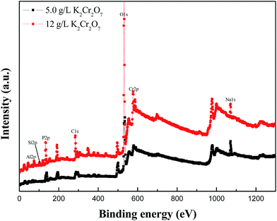 | ||
| Fig. 3 XPS survey spectra of green and black MAO coatings prepared in the electrolytes with 5.0 g L−1 and 12 g L−1 K2Cr2O7 addition on Al alloy substrate after Ar sputtering. | ||
Typical Cr 2p high-resolution XPS spectra of the green and black MAO coatings with 5.0 g L−1 and 12 g L−1 K2Cr2O7 additions after Ar sputtering is shown in Fig. 4. The deconvolution of Cr 2p3/2 and Cr 2p1/2 peaks of the green MAO coating gives two peaks, shown in Fig. 4(a), and the deconvolution of Cr 2p3/2 peak gives only one peak at 576.5 eV, which is assigned to Cr2O3 bonds. It is well known that Cr2O3 often appears green color, which further proved that this Cr oxide resulted in a green MAO coating. The deconvolution of Cr 2p3/2 and Cr 2p1/2 peaks of the black MAO coating was shown on Fig. 4(b), and it gives four peaks. For the deconvolution of Cr 2p3/2 peak, it gives two peaks at 576.5 eV and 580 eV, which are assigned to Cr2O3 and CrO3 bonds. It is also known that CrO3 appears dark red, and red (CrO3) and green (Cr2O3) can synthesize black. This was the reason for the formation of the black MAO coating. Furthermore, it could be speculated that the properties of the MAO coatings might be also different due to their different microstructure.
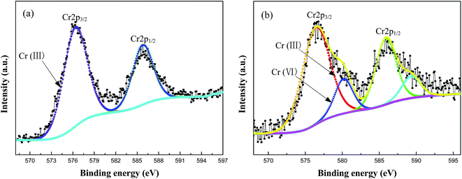 | ||
| Fig. 4 Typical Cr 2p high-resolution XPS spectrum of (a) green MAO coating and (b) black MAO coating on Al alloy substrate after Ar sputtering. | ||
3.2 Mechanical property
In this experiment, hardness (H) values at a 10% depth of the coating thickness were considered as representative of the Al alloy substrate and five MAO coatings. The results represented H values of four indents on each sample, shown in Fig. 5. Compared with the Al alloy substrate, the H values of all MAO coatings were improved significantly. With increase of the concentration of K2Cr2O7 colorant, the H values of MAO coatings were increased first and then reduced, and the H maximum values were obtained when the concentrations of K2Cr2O7 colorant were 2.5 g L−1 and 5 g L−1. It was known that a large amount of Al2O3 phase was obtained in the base solution or with a little of K2Cr2O7 colorant addition into the solution, and so the hardness was dominated by aluminum oxide. As the K2Cr2O7 colorant increased to 8 g L−1 and 12 g L−1, the chromium oxide phase had been increased and the MAO coatings turned to be more compact. Compared with the Al2O3 phase, the two chromium oxide phases had low H values. So the H values of MAO coatings presented the above variation under the interaction of different phase composition and coating compactness. Table 2 shows the results of hardness (H), elastic modulus (E) and values of H/E of the Al alloy substrate and the MAO coatings. It has been reported that the relative magnitudes of elastic deformation and plastic deformation under the action of compressive force could be characterized by the values of H/E, and a larger value of H/E corresponded to a better wear resistance.26,27 So it could be estimated that the Cr-incorporated MAO coatings had an improved wear resistance for the excellent toughness of chromium oxide phase in the MAO coating.28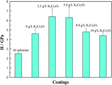 | ||
| Fig. 5 H values of different coatings–substrate systems, Al substrate, MAO coatings with 0 g L−1, 2.5 g L−1, 5.0 g L−1, 8.0 g L−1, 12 g L−1 K2Cr2O7. | ||
| Coatings | Hardness (H)/GPa | Elastic modulus (E)/GPa | H/E |
|---|---|---|---|
| Al alloy substrate | 2.5 | 106 | 0.024 |
| 0 g L−1 K2Cr2O7 | 4.6 | 100 | 0.046 |
| 2.5 g L−1 K2Cr2O7 | 6.4 | 123 | 0.052 |
| 5.0 g L−1 K2Cr2O7 | 6.3 | 112 | 0.056 |
| 8.0 g L−1 K2Cr2O7 | 4.8 | 106 | 0.045 |
| 12 g L−1 K2Cr2O7 | 4.4 | 82 | 0.053 |
3.3 Tribological property
Fig. 6 presents the friction coefficient of Al alloy substrate and five different MAO coatings against sliding time. For Al alloy substrate, there were some obvious “peaks” in the friction curve and the frictional coefficient was about 0.55. The three MAO coatings, prepared in the base solution and in the electrolytes with 2.5 g L−1 or 8 g L−1 K2Cr2O7 as colorant addition, had a similar change regulation of the frictional coefficient. Namely, the fluctuation of the three friction curves was small compared with Al alloy substrate, and the friction coefficient increased with the increase of wear time. Finally, the friction coefficient of the three MAO coatings could reach about 0.6, which was related to a porous surface structure and their mechanical properties. In the case of the MAO coatings prepared in the electrolytes with 5 g L−1 or 12 g L−1 K2Cr2O7 colorant addition, the friction coefficient increased first and then tended to be stable (0.48 and 0.43, respectively) along with the sliding time, which presented that these two coatings could exhibit a good tribological behavior. Especially, the black MAO coating with a high Cr content prepared in the electrolyte with 12 g L−1 K2Cr2O7 colorant addition had the lowest friction coefficient. The fracture toughness of chromium oxide phase in the ceramic coating made anti-wear property of 10 min coating relatively stable. So it could be deduced that the tribological behavior of the MAO coatings was related to their surface porous structure and Cr contents in the coatings. It was noted that the trend of the change of friction coefficient with wear time in this experiment was different from the ref. 29, and there was no obviously decreased during the friction process. This was in accordance with the experimental result reported by Zhang et al.30 So it could be speculated that the toughened phase (chromium oxide) changed the tribological behavior of the MAO coatings. Furthermore, the wear mechanism was studied by the SEM + EDS analysis of the wear track.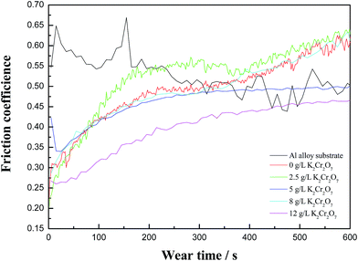 | ||
| Fig. 6 Coefficient of friction (COF) of Al alloy substrate and MAO coatings with 0 g L−1, 2.5 g L−1, 5.0 g L−1, 8.0 g L−1, 12 g L−1 K2Cr2O7 as a function of sliding time. | ||
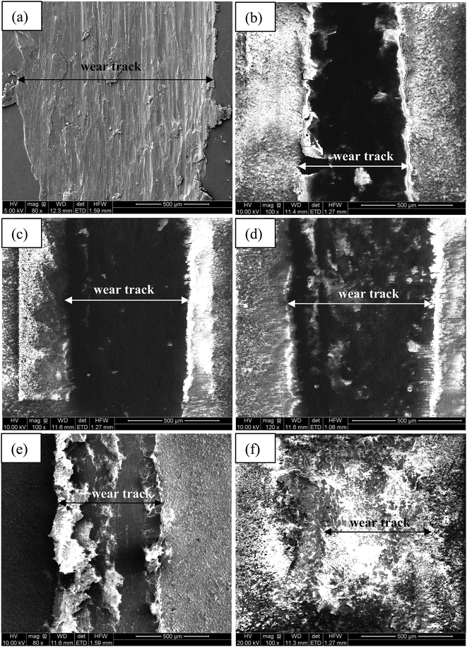
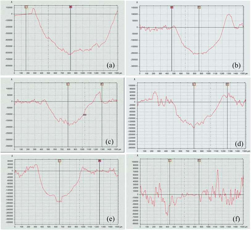
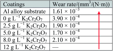
Fig. 7 illustrates the morphologies of wear tracks on the Al alloy substrate and MAO coatings, and the partially elaborated chemical composition of wear tracks by EDS is shown in Table 3. Fig. 8 shows the surface profiles of the wear tracks in the uncoated and coated Al alloy. The surface characteristics of adhesive wear were presented on the Al alloy substrate due to the Al alloy plastic deformation, as shown in the insert of Fig. 7(a). A large amount of Al and very little of O were found on the Al substrate surface of wear track, which indicated that vigorous oxidation did not occur during the friction process. The surface profile taken by a profilometer showed deep and wide wear track on the uncoated Al alloy surface (Fig. 8(a)). A serious ploughing wear occurred on the MAO coated Al alloy substrates, and the MAO coatings were partly peeling off from Al alloy substrates during wear process, as shown in the insert of Fig. 7(b)–(e). Compared with the Al alloy substrate, the surface profiles still showed deep and wide wear tracks on the Al alloy surface (Fig. 8(b)–(e)). It was also found that the contents of Al, O, Si and P elements on the surface of wear tracks were similar. The contents of Cr slightly increased with the increase of K2Cr2O7 colorant addition. This indicated that these four MAO coatings had a similar tribological behavior during the friction process. On the contrary, the wear track of the black MAO coating prepared in the electrolyte with 12 g L−1 K2Cr2O7 addition was smooth and unnoticeable (Fig. 7(f)). The surface profile of the wear track was difficult to observe, as shown in Fig. 8(f). It was also proved that the wear resistance of Cr-incorporated MAO coatings had been strongly improved. Compared with the other MAO coatings, amount of Cr (chromium oxide) existed in the wear track of this black MAO coating and it was worth noticing that Co and W elements from the grinding ball was discovered, which revealed that the Cr-incorporated MAO coating with high Cr content provided a good protection for the Al substrate. As a result, the wear rates of the MAO coatings were all decreased (about one order of magnitude) compared with the Al alloy substrate, shown in Table 4. Especially, the cross-sectional area of the black MAO coating prepared in the electrolyte with 12 g L−1 K2Cr2O7 addition was unnoticeable and thus the wear rate could not be obtained due to the unnoticeable wear track under the identical experimental conditions. So it had the best wear resistance among the MAO coatings.
| Coatings | O/at% | Al/at% | Si/at% | P/at% | Cr/at% | Co/at% | W/at% |
|---|---|---|---|---|---|---|---|
| Al alloy substrate | 2.74 | 95.87 | 0.85 | 3.10 | — | — | — |
| 0 g L−1 K2Cr2O7 | 72.10 | 23.95 | 0.90 | 2.75 | — | — | — |
| 2.5 g L−1 K2Cr2O7 | 72.60 | 21.69 | 1.48 | 3.66 | 0.27 | — | — |
| 5.0 g L−1 K2Cr2O7 | 70.25 | 27.98 | 0.36 | 0.85 | 0.50 | — | — |
| 8.0 g L−1 K2Cr2O7 | 71.53 | 24.20 | 0.70 | 2.30 | 1.22 | — | — |
| 12 g L−1 K2Cr2O7 | 73.78 | 13.86 | 1.08 | 3.09 | 5.28 | 0.47 | 2.36 |
3.4 Corrosion resistance
The polarization curves of the MAO coated 6061 Al alloy in the 3.5 wt% NaCl solution were shown in Fig. 9. Corrosion potential and corrosion current density obtained from Fig. 9 by Tafel analysis were shown in Table 5. It was found that the corrosion current densities of these MAO coatings with Cr addition were decreased comparing with the MAO coating without Cr addition, which indicated that these green and black MAO coatings all had improved corrosion resistance. Especially, the corrosion current density of the black MAO coating was 2 orders of magnitude lower than the MAO coating without Cr addition, which was related to a self-sealing MAO coating obtained with K2Cr2O7 addition into the solution and it could isolate the corrosive medium to improve the corrosion resistance. This self-sealing black MAO coating might play a similar role with the references of Kaihui Dong for improving the corrosion resistance.19,20 It is worth noting that this self-sealing black MAO coating and the MAO coating prepared in the solution with 8 g L−1 K2Cr2O7 addition had low corrosion potential, which demonstrated that the tendency of the corrosion could be increased and the galvanic corrosion might be enhanced due to the Cr element in the MAO coating.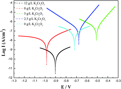 | ||
| Fig. 9 Polarization curves of MAO coatings prepared in the electrolytes with different K2Cr2O7 additions, 0 g L−1, 2.5 g L−1, 5.0 g L−1, 8.0 g L−1, 12 g L−1. | ||
| Coatings | Corrosion current density (A cm−2) | Corrosion potential (V) |
|---|---|---|
| 0 g L−1 K2Cr2O7 | 3.59 × 10⁻⁷ | −0.72 |
| 2.5 g L−1 K2Cr2O7 | 1.64 × 10⁻⁷ | −0.68 |
| 5.0 g L−1 K2Cr2O7 | 2.65 × 10⁻⁷ | −0.51 |
| 8.0 g L−1 K2Cr2O7 | 1.96 × 10⁻⁸ | −0.99 |
| 12 g L−1 K2Cr2O7 | 1.10 × 10⁻⁹ | −0.90 |
4. Conclusions
(1) A novel Cr-containing electrolyte solutions were used to obtain the self-sealing MAO coating with black color. Compared to the traditional MAO coating, the green MAO coating only contained Cr2O3 phase as a little of K2Cr2O7 was added into the base electrolyte and the self-sealing black MAO coating contained Cr2O3 and CrO3 phases as a mount of K2Cr2O7 was added into the base electrolyte.(2) H values of the MAO coatings increased first and then decreased with the increase of Cr at% in the coatings. H/E values indicated that the wear resistance of Cr-incorporated MAO coatings was improved compared with the MAO coating prepared in the base solution.
(3) The self-sealing black MAO coating exhibited the best wear resistance and corrosion performance among the five MAO coatings, which attributed to a self-sealing dense surface structure and chromium oxide phase with high toughness distributed in the Al2O3 phase.
Acknowledgements
This study was funded by the financial support of the Natural Science Foundation of China (Grant number 51571114 and 11504284) and Natural Science Foundation of Shaanxi Province (Grant number 2015JM5176). The authors would like to express their special thanks to Dr Z. Y. Wang and Dr P. Guo (at Ningbo Institute of Material Technology & Engineering, Chinese Academy of Sciences) for their help in characterizing MAO coatings for this paper.References
- T. Dursun and C. Soutis, Mater. Des., 2014, 56, 862–871 CrossRef CAS.
- R. I. Rodriguez, J. B. Jordon, P. G. Allison, T. Rushing and L. Garcia, Mater. Sci. Eng., A, 2016, 654, 236–248 CrossRef CAS.
- C. H. Liu, J. Chen, Y. X. Lai, D. H. Zhu, Y. Gu and J. H. Chen, Mater. Des., 2015, 87, 1–5 CrossRef CAS.
- D. Snihirova, S. V. Lamaka and M. F. Montemor, Smart Composite Coatings and Membranes, 2016, 85–121 Search PubMed.
- S. Thibault and E. Hug, Appl. Surf. Sci., 2014, 310, 311–316 CrossRef CAS.
- M. R. Rokni, C. A. Widener and V. R. Champagne, Appl. Surf. Sci., 2014, 290, 482–489 CrossRef CAS.
- P. Santa Coloma, U. Izagirre, Y. Belaustegi, J. B. Jorcin, F. J. Cano and N. Lapeña, Appl. Surf. Sci., 2015, 345, 24–35 CrossRef CAS.
- R. U. Din, V. C. Gudla, M. S. Jellesen and R. Ambat, Surf. Coat. Technol., 2016, 296, 1–12 CrossRef CAS.
- D. J. Kong, H. Liu and J. C. Wang, J. Alloys Compd., 2015, 650, 393–398 CrossRef.
- Y. Yang and L. L. Zhou, J. Mater. Sci. Technol., 2014, 30, 1251–1254 CAS.
- D. J. Shen, G. L. Li, C. H. Guo, J. Zou, J. R. Cai, D. L. He, H. J. Ma and F. F. Liu, Appl. Surf. Sci., 2013, 287, 451–456 CrossRef CAS.
- D. J. Shen, J. Zou, L. L. Wu, F. F. Liu, G. L. Li, J. R. Cai, D. L. He, H. J. Ma and G. R. Jiang, Appl. Surf. Sci., 2013, 265, 431–437 CrossRef CAS.
- A. L. Yerokhin, X. Nie, A. Leyland, A. Matthews and S. J. Dowey, Surf. Coat. Technol., 1999, 122, 73–93 CrossRef CAS.
- A. S. Gnedenkov, S. L. Sinebryukhov, D. V. Mashtalyar and S. V. Gnedenkov, Corros. Sci., 2016, 102, 348–354 CrossRef CAS.
- L. Chen, J. Han and S. X. Yu, Rare Met., 2006, 25, 146–149 CrossRef.
- J. M. Li, H. Cai and B. L. Jiang, Surf. Coat. Technol., 2007, 201, 8702–8708 CrossRef CAS.
- T. G. Zhao, Preparation technology and structure of green oxide film by micro-arc oxidation on aluminum alloy, Dong Shan, 2015 Search PubMed.
- X. J. Cui, C. H. Liu, R. S. Yang, M. T. Li and X. Z. Lin, Surf. Coat. Technol., 2015, 269, 228–237 CrossRef CAS.
- K. H. Dong, Y. W. Song, D. Y. Shan and E. H. Han, Surf. Coat. Technol., 2015, 266, 188–196 CrossRef CAS.
- K. H. Dong, Y. W. Song, D. Y. Shan and E. H. Han, Corros. Sci., 2015, 100, 275–283 CrossRef CAS.
- Y. W. Song, K. H. Dong, D. Y. Shan and E. H. Han, J. Magnesium Alloys, 2013, 1, 82–87 CrossRef CAS.
- C. Liu, N. Fiol, J. Poch and I. Villaescusa, Journal of Water Process Engineering, 2016, 11, 143–151 CrossRef.
- W. Yang, J. L. Wang, D. P. Xu, J. H. Li and T. Chen, Surf. Coat. Technol., 2015, 283, 281–285 CrossRef CAS.
- W. Yang, B. L. Jiang, A. Y. Wang and H. Y. Shi, J. Mater. Sci. Technol., 2012, 28, 707–712 CAS.
- J. H. Dou, H. J. Yu, C. Z. Chen, Y. K. Pan, D. D. Gao and X. H. Zhang, Mater. Lett., 2016, 164, 575–578 CrossRef CAS.
- G. S. Fox-Rabinovich, B. D. Beake, J. L. Endrino, S. C. Veldhuis, R. Parkinson, L. S. Shuster and M. S. Migranov, Surf. Coat. Technol., 2006, 200, 5738–5742 CrossRef CAS.
- C. H. Hsu, K. L. Chen, Z. H. Lin, C. Y. Su and C. K. Lin, Thin Solid Films, 2010, 518, 3825–3829 CrossRef CAS.
- X. L. Pang, K. W. Gao, H. S. Yang and Y. B. Wang, Chin. J. Vac. Sci. Technol., 2008, 28, 420–423 CAS.
- N. Xiang, R. G. Song, J. Zhao, H. Li, C. Wang and Z. X. Wang, Trans. Nonferrous Met. Soc. China, 2015, 25, 3323–3328 CrossRef CAS.
- L. Zhang, W. Zhang, Y. Han and W. Tang, Appl. Surf. Sci., 2016, 361, 141–149 CrossRef CAS.
| This journal is © The Royal Society of Chemistry 2017 |

