 Open Access Article
Solution processed high refractive index contrast distributed Bragg reflectors†
Miguel
Anaya
,
Andrea
Rubino
,
Mauricio E.
Calvo
* and
Hernán
Míguez
*
Instituto de Ciencia de Materiales de Sevilla, Consejo Superior de Investigaciones Científicas-Universidad de Sevilla, Calle Américo Vespucio 49, 41092 Sevilla, Spain. E-mail: h.miguez@csic.es; mauricio.calvo@icmse.csic.es
First published on 4th April 2016
Abstract
We have developed a method to alternate porous and dense dielectric films in order to build high refractive index contrast distributed Bragg reflectors (DBRs) capable of reflecting very efficiently in a targeted spectral range employing a small number of layers in the stack. Porous layers made of SiO2 nanoparticles and compact sol–gel processed TiO2 layers are sequentially deposited. The key to the preservation of porosity of every other layer during the deposition process is the use of a sacrificial layer of polystyrene that prevents the infiltration of the interstitial voids between nanoparticles with the homogeneous solution of TiO2 precursors. Our approach allows preparing a series of DBRs operating along the whole visible spectral range. Reflectance values as high as 90% are achieved from only seven layers. The particular distribution of porosity along one direction gives rise to an interesting interplay between the optical properties of the system and the vapor pressure in the surrounding atmosphere, which we foresee could be put into practice in gas sensing devices.
Introduction
Superior performance, low-cost processing and ease of integration are sine quibus non conditions for novel materials to be used in advanced technologies amenable to mass production. In this context, solution processed dielectric nanostructures for light management have increasingly attracted interest due to their potential for improving the performance of optoelectronic devices.1–3 Within the large family of dielectric optical materials, distributed Bragg reflectors (DBRs) are probably among the first and most basic designs that have been employed for this purpose.4 A DBR typically consists of two different compounds alternately stacked to produce a periodic modulation of the refractive index (n) in one dimension of the space. As a consequence of this, strong interference phenomena occur and selective light reflection at certain wavelengths ranges is achieved.5 Both the spectral position and the intensity of the reflectance peak (or Bragg peak) depend on the thickness, the refractive index and the number of slabs deposited. The use of DBRs is nowadays widespread in numerous fields, being found in many systems as passive elements acting like frequency selective mirrors, filters or optical resonators.6,7 By integrating them with light absorbing or/and emitting materials, DBRs find very relevant applications in the fields of lighting and solar energy, where they are used to enhance light harvesting or photoluminescence processes.8–13The larger the dielectric contrast between alternate layers is, the lower the number of slabs required in the stack to achieve a certain reflectance value and wider the spectral width at which it occurs. For DBRs operating in the visible range, silicon oxide (SiO2) and titanium oxide (TiO2) are typical materials of choice due to the large refractive index difference they present. An alternative approach to high refractive index contrast DBRs is based on the alternation of layers with different porosities. This idea has been put into practice for the realization of DBRs made of a variety of compositions,14–20 including those in which a single compound is used.21–23 Techniques employed to achieve this alternation of porosities are diverse and include, among others, physical vapour deposition,14,15,20,21 electrochemical acid etching,22 and liquid processing.16–18,24 Besides, the presence of controlled porosity in DBRs has enormously expanded their range of applications in many relevant fields in recent years.25 For example, opto-electronic and optofluidic devices may benefit from the diffusion of species through a network of accessible and interconnected voids within a mirror or an optical resonator.18,26–32
From the point of view of wet chemistry, the combination of different porosities in the same stack is a challenge that has been mainly addressed following two different strategies. In one approach, porosity can be created or increased within the low refractive index layer by the inclusion of a porogene. This compound remains in the layer avoiding the infiltration of a freshly deposited top layer until it is removed by thermal or chemical treatment. After porogene elimination, an open interconnected33–35 or an occluded and not accessible porosity is obtained.36 On the other hand, suspensions with nanoparticles in different aggregation states can be used as precursors to alternately deposit thin layers with different porosities.17,37,38 Nanoparticle layers are advantageous because of their stability against disassembly under solvent immersion, allowing the subsequent deposition of a new layer of nanoparticles. When nanoparticles of very small size are deposited on top of a layer of large nanoparticles, the risk of losing dielectric contrast can be prevented by using a sacrificial polymer that impedes their interpenetration.39
Herein, we explore the limit of this sacrificial polymer approximation to build DBRs with maximized reflectance. We describe a general synthetic procedure to obtain high refractive index contrast DBRs based on the alternation of dense sol–gel processed TiO2 films and highly porous SiO2 nanoparticle layers. During the deposition of the liquid precursors of the dense layers, the porosity of the low refractive index ones is preserved by prior filling of the interstitial voids with a sacrificial polymer that is eliminated at the end of the process. The key to create a stack of high structural quality lies in preventing the infiltrating polymer to create a film above the protected nanoparticle layer, since that would cause the collapse of the structure when the polymer is eventually removed. By this means, we show that it is possible to build multilayers displaying an intense reflectance band of above 90% employing only a small number of dielectric layers in the stack. Such a band can be tuned to sweep the whole visible region of the electromagnetic spectrum by adjusting the thickness of the layers. While the potential of these new materials in the field of emerging photovoltaic devices has been recently demonstrated, here we focus on the analysis of the evolution of their optical properties to varying environmental conditions. Vapour diffusion and condensation properties of the two types of layers present in the stack determines the response of the system and can be potentially put into practice in new sensing devices.
Results and discussion
The choice of TiO2 and SiO2 to build colored DBRs with enhanced refractive index contrast is supported by the fact that they present, respectively, one of the highest and the lowest refractive indices among all transparent materials in the visible range. Besides, they present other attractive properties such as ease of processing, low toxicity and low cost, which make them amenable to device integration and mass production. Dense TiO2 layer precursors were prepared by a sol–gel route and deposited employing a spin-coating technique, as described in detail in the Experimental section. By this means we expected to attain a refractive index of around n = 2.2 in the center of the visible spectrum, as it has been reported in the literature.Regarding the low refractive index material, as far as we know, the transparent porous layer with the lowest refractive index reported is one based on MgOF prepared by wet deposition.40 However the integration of this material in a DBR is seemingly not feasible due to its collapse during the sequential stacking required to build the DBR, as we demonstrate in the ESI† (Fig. S1). Hence, in order to improve with respect to the value attainable with dense silica prepared by the sol–gel process (n = 1.45), we employed a strategy based on the deposition of SiO2 nanoparticles which we have previously demonstrated that might allow reaching values as low as n = 1.22.41 In fact, thin optical quality layers with n < 1.25 are scarce in the field of solution processed materials, some examples being CaF242 or MgF2,43 whose preparation is also not easily compatible with the processing of a multilayer, or mesostructured SiO2 layers, whose preparation involves the use of organic supramolecular templates and lengthy stabilization treatments.
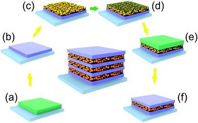
In contrast, thin layers of SiO2 nanoparticles have been proven to be robust enough to support the stacking of different types of particles and can be easily deposited by spin coating or dip-coating.12,17,44 However, their use faces the problem of infiltration when combined with the deposition of a continuous phase from a liquid dispersion. In order to overcome this obstacle, we propose a procedure based on the temporary filling of the interstitial void between nanoparticles with a polymer, as it is described in the scheme of Fig. 1. After deposition and thermal treatment of a first dense TiO2 layer (Fig. 1a and b), we stacked a layer of SiO2 nanoparticles (Fig. 1c). Next, we placed some drops of polystyrene (PS) solution and started the spin coating. Polystyrene is forced to fill the voids of the SiO2 nanoparticle layer and blocks the access to the pore network (Fig. 1d). As polystyrene is insoluble in isopropanol, the precursors of a new TiO2 layer deposited on top of this hybrid SiO2–PS layer cannot percolate through it (Fig. 1e). Finally, a thermal shock treatment at 500 °C further densifies the TiO2 layer and causes the thermal decomposition and removal of the PS from the SiO2 layer pores (Fig. 1e). The parameters related to the deposition of the PS layer have been appropriately set to obtain a complete filling of the porous underlying layer and, at the same time, minimize the accumulation of polystyrene on the top. Otherwise, the eventual thermal annealing of that excess of polystyrene can compromise the mechanical stability of the ensemble. Sequential repetition of these steps until the desired number of slabs is deposited leads to the formation of a multilayer.
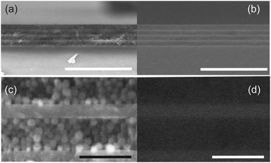
In Fig. 2 we show secondary electron (SE, Fig. 2a and c) and backscattered electron (BSE, Fig. 2b and d) images simultaneously taken from the same area of a cross section of a nine-layer DBR made by alternating compact TiO2 and porous SiO2. Fig. 2a and b disclose smooth and continuous interfaces between both types of layers with high uniformity at the microscale. Each type of layer can be recognized by their different morphology in SE images as well as by their different response in BSE ones. In the latter, brighter regions indicate the presence of elements of higher atomic number. High magnification images (Fig. 2c and d) reveal the spherical morphology of the SiO2 nanoparticles and the homogeneity and continuity of the compact TiO2 layer, as well as the absence of interpenetration between both types of layers.
X-ray reflectivity (XRR) characterization was employed to evaluate the density of the layers. Although it was not possible to obtain reliable data for the case of the silica layers, XRR data taken from TiO2 layers allowed estimating a density of 3.11 g cc−1, in very good agreement with reported data for dense TiO2.45 Full details are provided in the ESI,† and Fig. S2 therein.
As we mentioned above, the modulation of the refractive index along one dimension of the space leads to the occurrence of strong interference effects. When these effects are spectrally located in the visible region of the electromagnetic spectrum, bright colors can be seen by the naked eye. In Fig. 3, a picture of a series of seven layer DBRs supported on glass slides is displayed, the color gamut covering the whole visible range.
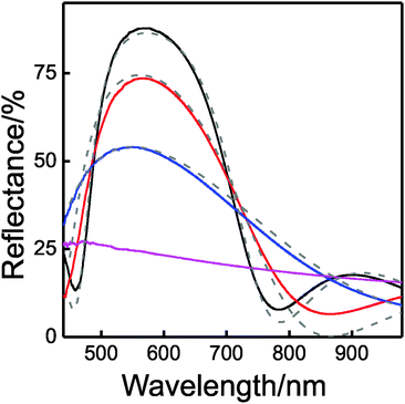
The evolution of the reflectance of these types of DBRs with a number of layers can be seen in Fig. 4. It can be observed that with only 3 layers (TiO2/SiO2/TiO2, blue solid line) the measured reflectance reaches values as high as 50%, and increasing up to 75% and 90% when two and four extra layers are added, respectively, (red and black solid lines). Porosity of the individual layers of the DBR can be estimated through the fitting of these reflectance spectra using a code based on a full vector wave transfer matrix approximation.46 The simulated spectra (dashed lines in Fig. 4) are in fair agreement with the experimental ones. Refractive indices of 2.12 and 1.29 for TiO2 and SiO2 layers, respectively, were considered for 400 nm < λ < 800 nm for these calculations. This implies that the refractive index contrast is 0.83, one of the highest values achieved for a solution processed DBR, which are 0.87 and 0.84, as reported in ref. 34 and 36, respectively. Please notice that the estimated refractive index for the SiO2 layer is slightly larger than the expected one, which ranged between 1.23 and 1.25.17,18 This may indicate that a small percentage of interstitial volume in the SiO2 layer is filled by the liquid dispersion of TiO2 precursors, which could be due to incomplete filling of such volume with polystyrene or permeation of the precursors through the sacrificial layer. We can estimate that only 5% of the free space in SiO2 layers is filled with TiO2. It is important to remark that the optical constants of both types of layers remain unaltered as the DBR is constructed. This conclusion demonstrates that the minor infiltration of the SiO2 layer is not an accumulative process but it takes place only when each new SiO2/TiO2 interface is created.
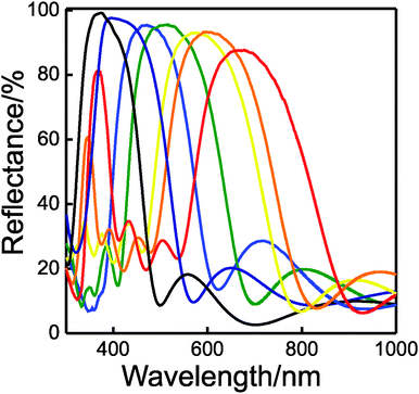
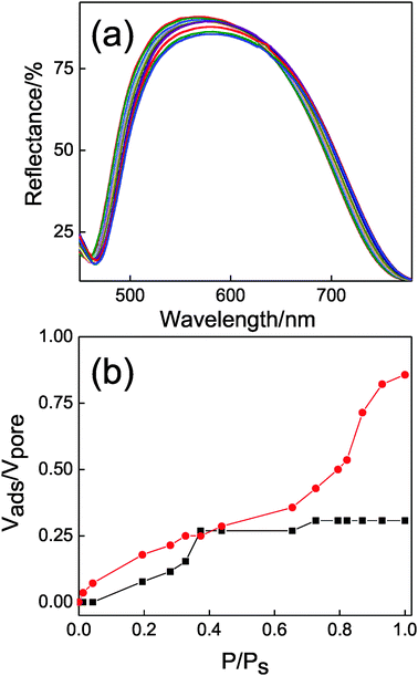
In Fig. 5, we plot the experimental reflectance spectra obtained by a series of 7-layer-1DPCs prepared by combining non-porous TiO2 and highly porous SiO2. It can be observed that the values of the maximum oscillate between 86% and 96%.
On the other hand, the value of the normalised spectral width of the Bragg peak, calculated as Δλ/λBragg (Δλ being the FWHM and λBragg being the spectral position of the Bragg peak) was found to be close to 0.37, similar to what has been achieved with the best efforts put forth in the field in the past.34,36
It is interesting to notice that the porosities estimated from the refractive index values obtained employing Bruggeman's model are 12% and 35% for TiO2 and SiO2, respectively. This means that the compact TiO2 slab is not dense stricto sensu, but it presents certain porosity not observable under the scanning electron microscope that must therefore correspond to the presence of micropores. In order to further analyse the interstitial sites present in the DBRs we employed a porosimetry technique based on specular reflectance.47 It has been shown that when the open pores of a multilayer displaying a Bragg peak are gradually infiltrated by a guest compound, the induced changes in the refractive index of the layers give rise to a red-shift in the spectral position of the Bragg peak and a modification of its intensity.48 By monitoring in situ these variations as we increase and lower the pressure of a vapor (isopropanol in our case) in a chamber in which the DBR is placed, we can obtain a complete adsorption–desorption isotherm cycle, from which very detailed information on the pore structure can be obtained.16 The evolution of the Bragg peak for a complete adsorption/desorption cycle is depicted in Fig. 6a. By fitting these spectra we can evaluate the pore volume that is progressively filled in each type of layer present in the sample as vapor pressure increases. The results are shown in Fig. 6b. Abrupt changes in the spectral position and intensity of the Bragg peak are observed for P/Ps > 0.65 and correspond to vapor condensation within the SiO2 layer pore network, which is made of almost monodispersed nanoparticles, hence presenting a narrow pore size distribution. Contrarily, adsorption within the much more compact TiO2 lattice takes place smoothly, confirming the previously suggested hypothesis of the presence of micropores. The response to changes in the ambient atmosphere also demonstrates that this microporosity is partially open.
These DBRs can also be infiltrated from the liquid phase. As an example, we took some organic solvents commonly employed in the preparation of optoelectronic devices by liquid processing. Fig. S4 (ESI†) shows the reflectance spectra of a 1DPC before and after infiltration with three different liquids. The experiment is done in such a way that the only possible entrance to the structure is through the less porous TiO2 layer. The liquid drop is placed on top of the stack and at its center, hence avoiding any potential infiltration by the side. As in the case of gas phase compounds, as the liquids fill the voids in the structure, the Bragg peak shifts to longer wavelengths, this change being proportional to the refractive indices of the guest fluid.
Conclusions
We have demonstrated a solution processed route to achieve high refractive index contrast distributed Bragg reflectors. These types of systems present the ability to reflect over 90% of the incoming light in the desired spectral ranges employing only a few periods in the stack. These highly reflecting dielectric structures are less than 500 nm thick. We have also shown that these characteristics are accompanied by the possibility of infiltrating gas or liquid phase compounds into the photonic structure, giving rise to spectral variations in their optical response. These entire attributes make the system reported herein a potential candidate for integration in technologies that make use of thin films, such as photovoltaics or sensing, in order to provide them with enhanced optical performance.Experimental
Liquid dispersions
TiO2 precursor dispersion synthesis was made by adding 0.254 ml (named T1) or 0.381 ml (named T2) of titanium tetraisopropoxide (TTIP, Sigma Aldrich, 377![[thin space (1/6-em)]](https://www.rsc.org/images/entities/char_2009.gif) 996) under strong stirring to a solution that contains 0.034 ml of water and 0.034 ml of 2 M hydrochloric acid in 3.38 ml of ethanol. Once TTIP is added, the resulting mixture is kept under stirring for one hour before use.
996) under strong stirring to a solution that contains 0.034 ml of water and 0.034 ml of 2 M hydrochloric acid in 3.38 ml of ethanol. Once TTIP is added, the resulting mixture is kept under stirring for one hour before use.
SiO2 suspension was purchased from Sigma-Aldrich (Ludox TMA 420859). Particle suspension is diluted in ethanol to reach desired suspensions with final concentrations between 1% and 4%.
Polystyrene solution is made by dissolving an appropriate amount of solid polystyrene (Aldrich, 182427) in toluene.
Multilayer deposition
A spin coating route combined with thermal treatment is chosen in order to control the thickness and the deposition of SiO2 and TiO2 layers, and to control the infiltration of the SiO2 porous layer by polystyrene. The scheme of the process is detailed in Fig. 1. In a typical multilayer process 200 μl of a TiO2 precursor dispersion is dropped on the top of a clean substrate (quartz, glass slide or silicon). The final rotation speed is set to 2000 rpm. This first layer is treated at 400 °C for 10 minutes. Next a layer of SiO2 nanoparticles (150 μl) is deposited from the suspension on top of the first TiO2 layer and spun at final speeds from 3000 rpm to 5000 rpm depending on the desired thickness. For each deposition step, the acceleration step is set in order to achieve the final rotation speed in one second. After that, 150 μl of the polystyrene solution (0.5 wt% toluene solution) is spin-casted onto the preformed multilayer structure. The amount of infiltrated polystyrene was controlled for each DBR through the final rotation speed, which was varied from 2000 rpm (thicker SiO2 layers) to 4000 rpm (thinner SiO2 layers). In Fig. S4 (ESI†), we show how the optical properties of a DBR are affected by the different polystyrene loads achieved. Then, a layer of TiO2 is deposited following the same protocol described before. The process is repeated until a desired number of layers are stacked.Structural characterization
FESEM images of the multilayer films deposited onto silicon were taken by using a microscope Hitachi 5200 operating at 5 kV.XRR data were collected using a Panalytical X'PERT PRO system in reflection mode. Cuκα radiation (40 mA, 45 KV) and a θ range from 0° to 9° were employed to obtain the reflectivity data.
Optical characterization
Reflectance spectra from 500 nm to 1200 nm were recorded using a Fourier transform spectrophotometer (Bruker IFS-66 FTIR) attached to a microscope and operating in reflection mode with a 4× objective with 0.1 of numerical aperture (light cone angle ±5.7°). The reflectance spectra in the 300 nm to 500 nm range were measured using an UV-Vis spectrophotometer (UV-2101PC, Shimadzu) attached with an integrating sphere. All spectra were corrected by a calibrated and NIST certified mirror (Ocean Optics catalogue #STAN-SSH-NIST).Fluid infiltration
Gradual vapor infiltration was done by placing the DBR sample into a closed chamber that has a quartz window. The chamber was designed to be placed in the optical pathway of the reflectance measurement system described above. Liquid isopropanol is kept in an isolated reservoir and it is introduced into the chamber by a manual valve system that also controls the pressure. As a result of this experimental setup, reflectance spectra can be recorded while the pressure is varied.Liquid infiltration was made by placing a few drops on top of the surface of the 1DPC and waiting for a couple of minutes before measuring. This permits the diffusion through the multilayer structure without the accumulation of liquid on top of the DBR.
Acknowledgements
The research leading to these results received funding from the European Research Council under the European Union's Seventh Framework Programme (FP7/2007–2013)/ERC grant agreement no. 307081 (POLIGHT) and the Spanish Ministry of Economy and Competitiveness under grant MAT2014 54852-R. MA is grateful to “La Caixa” Foundation for its financial support. FESEM characterization was performed at CITIUS, and we are grateful for its support.Notes and references
- P. Yeh, Optical Waves in Layered Media, John Wiley & Sons, Hoboken, New Jersey, 2005 Search PubMed.
- G. Kang, J. Yoo, J. Ahn and K. Kim, Nano Today, 2015, 10, 22–47 CrossRef CAS.
- M. Yoshimura, W. L. Suchanek and K. Byrappa, MRS Bull., 2000, 25, 17–25 CrossRef CAS.
- R. M. Almeida and S. Portal, Curr. Opin. Solid State Mater. Sci., 2003, 7, 151–157 CrossRef CAS.
- J. D. Joannopoulos, et al., Photonic crystals:molding the flow of light, Princeton University Press, Princeton, 2nd edn, 2008 Search PubMed.
- K. M. Chen, A. W. Sparks, H. C. Luan, D. R. Lim, K. Wada and L. C. Kimerling, Appl. Phys. Lett., 1999, 75, 3805 CrossRef CAS.
- D. C. Johnson, I. Ballard, K. W. J. Barnham, D. B. Bishnell, J. P. Connolly, M. C. Lynch, T. N. D. Tibbits, N. J. Ekins-Daukes, M. Mazzer, R. Airey, G. Hill and J. S. Roberts, Sol. Energy Mater. Sol. Cells, 2005, 87, 169–179 CrossRef CAS.
- L. Hou, Q. Hou, Y. Mo, J. Peng and Y. Cao, Appl. Phys. Lett., 2005, 87, 243504 CrossRef.
- R. Betancur, P. Romero-Gomez, A. Martinez-Otero, X. Elias, M. Maymó and J. Martorell, Nat. Photonics, 2013, 7, 995–1000 CrossRef CAS.
- P. Bermel, C. Luo, L. Zeng, L. C. Kimerling and J. D. Joannopoulos, Opt. Express, 2007, 15, 16986–17000 CrossRef CAS PubMed.
- K. Xie, M. Guo and H. Huang, J. Mater. Chem. C, 2015, 3, 10665–10686 RSC.
- A. Jiménez-Solano, J. M. Delgado-Sánchez, M. E. Calvo, J. M. Miranda-Muñoz, G. Lozano, D. Sancho, E. Sánchez-Cortezón and H. Míguez, Prog. Photovolt: Res. Appl., 2015, 23, 1785–1792 CrossRef.
- H. Shen, Z. Wang, Y. Wu and B. Yang, RSC Adv., 2016, 6, 4505–4520 RSC.
- J. J. Steele, A. C. van Popta, M. M. Hawkeye, J. C. Sit and M. J. Brett, Sens. Actuators, B, 2006, 120, 213 CrossRef CAS.
- L. Passoni, L. Criante, F. Fumagalli, F. Scotognella, G. Lanzani and F. Di Fonzo, ACS Nano, 2014, 8, 1216 CrossRef PubMed.
- M. C. Fuertes, F. J. López-Alcaraz, M. C. Marchi, H. E. Troiani, H. Míguez and G. J. A. A. Soler Illia, Adv. Funct. Mater., 2007, 17, 1247 CrossRef CAS.
- S. Colodrero, M. Ocaña and H. Míguez, Langmuir, 2008, 24, 4430 CrossRef CAS PubMed.
- L. D. Bonifacio, D. P. Puzzo, S. Breslav, B. M. Willey, A. McGeer and G. A. Ozin, Adv. Mater., 2010, 22, 1351–1354 CrossRef CAS PubMed.
- K. Szendrei, P. Ganter, O. Sánchez-Sobrado, R. Eger, A. Kuhn and B. V. Lotsch, Adv. Mater., 2015, 27, 6341–6348 CrossRef CAS PubMed.
- M. Muallem, A. Palatnik, G. D. Nessim and Y. R. Tischler, ACS Appl. Mater. Interfaces, 2015, 7, 474–481 CAS.
- M. F. Schubert, J. Q. Xi, J. K. Kim and E. F. Schubert, Appl. Phys. Lett., 2007, 90, 141115 CrossRef.
- E. J. Anglin, L. Cheng, W. R. Freeman and M. J. Sailor, et al. , Adv. Drug Delivery Rev., 2008, 60, 1266 CrossRef CAS PubMed.
- M. E. Calvo, S. Colodrero, T. C. Rojas, M. Ocaña, J. A. Anta and H. Míguez, Adv. Funct. Mater., 2008, 18, 2708 CrossRef CAS.
- C. Bronnbauer, J. Hornich, N. Gasparini, F. Guo, B. Hartmeier, N. A. Luechinger, C. Pflaum, C. J. Brabec and K. Forberich, Adv. Opt. Mater., 2015, 3, 1424–1430 CrossRef CAS.
- M. E. Calvo, S. Colodrero, N. Hidalgo, G. Lozano, C. Lopez-Lopez, O. Sanchez-Sobrado and H. Miguez, Energy Environ. Sci., 2011, 4, 4800–4812 Search PubMed.
- S. Colodrero, A. Mihi, L. Häggman, M. Ocaña, G. Boschloo, A. Hagfeldt and H. Míguez, Adv. Mater., 2009, 21, 764 CrossRef CAS.
- S. Guldin, M. Kolle, M. Stefik, R. Langford, D. Eder, U. Wiesner and U. Steiner, Adv. Mater., 2011, 23, 3664–3668 CrossRef CAS PubMed.
- W. Zhang, M. Anaya, G. Lozano, M. E. Calvo, M. B. Johnston, H. Míguez and H. J. Snaith, Nano Lett., 2015, 15, 1698–1702 CrossRef CAS PubMed.
- I. Pavlichenko, E. Broda, Y. Fukuda, K. Szendrei, A. K. Hatz, G. Scarpa, P. Lugli, C. Bräuchle and B. V. Lotsch, Mater. Horiz., 2015, 2, 299–308 RSC.
- L. Frezza, M. Patrini, M. Liscidini and D. Comoretto, J. Phys. Chem. C, 2011, 115, 19939 CAS.
- F. Scotognella, D. P. Puzzo, A. Monguzzi, D. S. Wiersma, D. Maschke, R. Tubino and G. A. Ozin, Small, 2009, 5, 2048 CrossRef CAS PubMed.
- M. Oliva-Ramirez, A. Barranco, M. Löffler, F. Yubero and A. R. González-Elipe, ACS Nano, 2016, 10, 1256 CrossRef CAS PubMed.
- (a) M. E. Calvo, N. Hildago, R. Schierholz, A. Kovàcs, A. Fernandez, M. G. Bellino, G. J. A. A. Soler-Illia and H. Miguez, Nanoscale, 2015, 7, 16582–16589 RSC; (b) N. Hidalgo, M. E. Calvo, M. G. Bellino, G. J. A. A. Soler-Illia and H. Míguez, Adv. Funct. Mater., 2011, 21, 2534–2540 CrossRef CAS.
- W. J. Nimens, L. Whittaker-Brooks and M. H. Bartl, J. Mater. Chem. C, 2016, 4, 668–672 RSC.
- B. V. Lotsch and G. A. Ozin, ACS Nano, 2008, 2, 2065 CrossRef CAS PubMed.
- B. Brudieu, A. Le Bris, J. Teisseire, f. Guillemont, G. Dantelle, S. Misra, P. Roca i Cabarrocas, F. Sorin and T. Gacoin, Adv. Opt. Mater., 2014, 2, 1105–1112 CrossRef CAS.
- J. H. Prosser, T. Brugarolas, S. Lee, A. J. Nolte and D. Lee, Nano Lett., 2012, 12, 5287–5291 CrossRef CAS PubMed.
- M. Anaya, M. E. Calvo, J. M. Luque-Raigón and H. Míguez, J. Am. Chem. Soc., 2013, 135, 7803–7806 CrossRef CAS PubMed.
- Y. Huang, J. T. Park, J. H. Prosser, J. H. Kim and D. Lee, J. Mater. Chem. C, 2014, 2, 3260–3269 RSC.
- D. Grosso, C. Boissière and C. Sanchez, Nat. Mater., 2007, 6, 572–575 CrossRef CAS PubMed.
- J. Bravo, L. Zhai, Z. Wu, R. E. Cohen and M. F. Rubner, Langmuir, 2007, 23, 7293 CrossRef CAS PubMed.
- A. Rehmer, K. Scheurell and E. Kemnitz, J. Mater. Chem. C, 2015, 3, 1716–1723 RSC.
- J. Noack, K. Scheurell, E. Kemnitz, P. Garcia-Juan, H. Rau, M. Lacroix, J. Eicher, B. Lintner, T. Sontheimer, T. Hofmann, J. Hegmann, R. Jahn and P. Löbmann, J. Mater. Chem., 2012, 22, 18535 RSC.
- P. Kurt, D. Banerjee, R. E. Cohen and M. F. Rubner, J. Mater. Chem., 2009, 19, 8920 RSC.
- M. C. Fuertes, M. Marchena, M. C. Marchi, A. Wolosiuk and G. J. A. A. Soler-Illia, Small, 2009, 5, 272–280 CrossRef CAS PubMed.
- G. Lozano, S. Colodrero, O. Caulier, M. E. Calvo and H. Míguez, J. Phys. Chem. C, 2010, 114, 3681 CAS.
- N. Hidalgo, C. López-López, G. Lozano, M. E. Calvo and H. Míguez, Langmuir, 2012, 28, 13777–13782 CrossRef CAS PubMed.
- M. E. Calvo and H. Mıguez, in Responsive Photonic Nanostructures: Smart Nanoscale Optical Materials, ed. Y. Yin, The Royal Society of Chemistry, Cambridge, UK, 2013, pp. 1–21 Search PubMed.
Footnote |
| † Electronic supplementary information (ESI) available: The SEM image of the TiO2/MgOF system, reactive concentration table, XRR data, and reflectance of DBR under liquid infiltration. See DOI: 10.1039/c6tc00663a |
| This journal is © The Royal Society of Chemistry 2016 |

