 Open Access Article
Creative Commons Attribution 3.0 Unported Licence
The morphology and structure of vanadyl phthalocyanine thin films on lithium niobate single crystals†
Alexandra J.
Ramadan
 *a,
Luke A.
Rochford
b,
Jonathan
Moffat
c,
Chris
Mulcahy
c,
Mary P.
Ryan
a,
Tim S.
Jones
b and
Sandrine
Heutz
*a
aDepartment of Materials, Imperial College London, Exhibition Road, London, SW7 2AZ, UK. E-mail: ar707@imperial.ac.uk; s.heutz@imperial.ac.uk
bDepartment of Chemistry, University of Warwick, Gibbet Hill Road, Coventry, CV4 7AL, UK
cAsylum Research an Oxford Instruments Company, Halifax Road, High Wycombe, Buckinghamshire, HP12 3SE, UK
First published on 7th December 2015
Abstract
The electric field of ferroelectric materials has been used as a driving force to promote molecular adsorption and control the orientation of small dipolar molecules. This approach has not been investigated on larger polyaromatic molecules, such as those used in organic electronic devices, even though the physical and electronic properties of thin films are strongly dependent on molecular structure and orientation, ultimately affecting device performance. Here we investigate the effects of model ferroelectric surfaces on a dipolar organic semiconducting molecule. Thin films of vanadyl phthalocyanine (VOPc) deposited on to (0001) and (2![[1 with combining macron]](https://www.rsc.org/images/entities/char_0031_0304.gif)
![[1 with combining macron]](https://www.rsc.org/images/entities/char_0031_0304.gif) 0) lithium niobate were subjected to structural and morphological analysis. Whilst thin films could be grown on these surfaces, no obvious change to their structure or morphology was observed suggesting there was no influence of a surface electrical field or surface chemistry on the film structure, and that the substrate is more complex than previously thought.
0) lithium niobate were subjected to structural and morphological analysis. Whilst thin films could be grown on these surfaces, no obvious change to their structure or morphology was observed suggesting there was no influence of a surface electrical field or surface chemistry on the film structure, and that the substrate is more complex than previously thought.
Introduction
This study investigates the effects of a ferroelectric substrate on the structure of molecular semiconductors grown onto them by organic molecular beam deposition (OMBD), using model single crystal ferroelectric systems. Lithium niobate (LiNbO3) has a high surface charge and in its single crystal (0001) face presents an orthogonal electric field.1 In contrast the (2![[1 with combining macron]](https://www.rsc.org/images/entities/char_0031_0304.gif)
![[1 with combining macron]](https://www.rsc.org/images/entities/char_0031_0304.gif) 0) surface does not possess this orthogonal field and is employed here as a control to determine whether any impact upon organic over-layer structure can be attributed to the electric field.2 The metallophthalocyanines (MPcs) are organic semiconducting molecules and their behaviour on a multitude of surfaces has been the subject of many investigations.3–8 Vanadyl phthalocyanine (VOPc), a non-planar molecule due to its V
0) surface does not possess this orthogonal field and is employed here as a control to determine whether any impact upon organic over-layer structure can be attributed to the electric field.2 The metallophthalocyanines (MPcs) are organic semiconducting molecules and their behaviour on a multitude of surfaces has been the subject of many investigations.3–8 Vanadyl phthalocyanine (VOPc), a non-planar molecule due to its V![[double bond, length as m-dash]](https://www.rsc.org/images/entities/char_e001.gif) O moiety lying orthogonal to the molecular plane, possesses a permanent electric dipole moment along this V
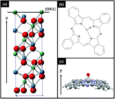
O moiety lying orthogonal to the molecular plane, possesses a permanent electric dipole moment along this V![[double bond, length as m-dash]](https://www.rsc.org/images/entities/char_e001.gif) O bond. The permanent dipole moment out of the ligand plane of the molecule is attractive for investigations on ferroelectric surfaces due to the potential for interactions between the molecular and surface dipoles.
O bond. The permanent dipole moment out of the ligand plane of the molecule is attractive for investigations on ferroelectric surfaces due to the potential for interactions between the molecular and surface dipoles.
In this work we report the structure and morphology of thin films of VOPc on two different types of (0001) and (2![[1 with combining macron]](https://www.rsc.org/images/entities/char_0031_0304.gif)
![[1 with combining macron]](https://www.rsc.org/images/entities/char_0031_0304.gif) 0) lithium niobate surfaces (Fig. 1). One set of substrates were prepared through simple substrate cleaning processes. The other set was prepared to produce atomically flat surfaces. We find that VOPc films adopt the same properties as on non-interacting substrates such as glass or silicon dioxide implying that ferroelectric surfaces are unable to significantly influence the growth of films of dipolar molecules.
0) lithium niobate surfaces (Fig. 1). One set of substrates were prepared through simple substrate cleaning processes. The other set was prepared to produce atomically flat surfaces. We find that VOPc films adopt the same properties as on non-interacting substrates such as glass or silicon dioxide implying that ferroelectric surfaces are unable to significantly influence the growth of films of dipolar molecules.
Experimental
Uniformly poled (0001) and (2![[1 with combining macron]](https://www.rsc.org/images/entities/char_0031_0304.gif)
![[1 with combining macron]](https://www.rsc.org/images/entities/char_0031_0304.gif) 0) 8 × 8 mm lithium niobate single crystals (Pi-Kem, UK) were cleaned by ultrasonication in acetone followed by isopropanol. Annealing was then undertaken using a Nabtherm (GmbH) LE/1/11/r6 box furnace. The crystals were heated (in air) initially to 200 °C at a rate of 10 °C min−1, then to 1000 °C at a rate of 100 °C min−1 where the crystals were held for 1 h. This process is a modified version of that previously reported by Bharath et al.9 Crystals were loaded into the UHV deposition chamber and heated at 155 °C for an hour prior to growth and analysis, and no change in LEED patterns was observed after this process. VOPc (Acros Organics, BE) was triply purified by thermal gradient sublimation10 and the resulting crystals were used for growth from a UHV evaporation cell (Karl Eberl GmbH) at 370 °C at a rate of 0.3 Å s−1. VOPc films were grown with an elevated substrate temperature (Tsub = 155 °C) in a custom built multi-chamber ultra-high vacuum (UHV) system with a base pressure better than 3 × 10⁻¹⁰ mbar. LEED patterns were collected with a SPECTALEED (Omicron®) rear-view MCP-LEED with nano-amp primary beam current. Images of these patterns were captured using a digital CCD camera interfaced to a personal computer. The substrate temperature was measured using a K-type thermocouple mounted close to the sample and calibrated using an optical pyrometer. Thin film XRD patterns were obtained using a Panalytical X'Pert Pro MRD diffractometer, with monochromatic Cu Kα1 radiation. AFM images were recorded using a Cypher AFM (Oxford Instruments Asylum Research, Santa Barbara, USA) in AC mode (tapping mode) using Olympus AC160-TS silicon tips.
0) 8 × 8 mm lithium niobate single crystals (Pi-Kem, UK) were cleaned by ultrasonication in acetone followed by isopropanol. Annealing was then undertaken using a Nabtherm (GmbH) LE/1/11/r6 box furnace. The crystals were heated (in air) initially to 200 °C at a rate of 10 °C min−1, then to 1000 °C at a rate of 100 °C min−1 where the crystals were held for 1 h. This process is a modified version of that previously reported by Bharath et al.9 Crystals were loaded into the UHV deposition chamber and heated at 155 °C for an hour prior to growth and analysis, and no change in LEED patterns was observed after this process. VOPc (Acros Organics, BE) was triply purified by thermal gradient sublimation10 and the resulting crystals were used for growth from a UHV evaporation cell (Karl Eberl GmbH) at 370 °C at a rate of 0.3 Å s−1. VOPc films were grown with an elevated substrate temperature (Tsub = 155 °C) in a custom built multi-chamber ultra-high vacuum (UHV) system with a base pressure better than 3 × 10⁻¹⁰ mbar. LEED patterns were collected with a SPECTALEED (Omicron®) rear-view MCP-LEED with nano-amp primary beam current. Images of these patterns were captured using a digital CCD camera interfaced to a personal computer. The substrate temperature was measured using a K-type thermocouple mounted close to the sample and calibrated using an optical pyrometer. Thin film XRD patterns were obtained using a Panalytical X'Pert Pro MRD diffractometer, with monochromatic Cu Kα1 radiation. AFM images were recorded using a Cypher AFM (Oxford Instruments Asylum Research, Santa Barbara, USA) in AC mode (tapping mode) using Olympus AC160-TS silicon tips.
Results and discussion
To prepare atomically flat surfaces of (0001) and (2![[1 with combining macron]](https://www.rsc.org/images/entities/char_0031_0304.gif)
![[1 with combining macron]](https://www.rsc.org/images/entities/char_0031_0304.gif) 0) lithium niobate, single crystals were annealed in air at 1000 °C for an hour. Once cooled the crystals were loaded into the ultra-high vacuum (UHV) chamber where low energy electron diffraction (LEED) measurements were carried out. The (2
0) lithium niobate, single crystals were annealed in air at 1000 °C for an hour. Once cooled the crystals were loaded into the ultra-high vacuum (UHV) chamber where low energy electron diffraction (LEED) measurements were carried out. The (2![[1 with combining macron]](https://www.rsc.org/images/entities/char_0031_0304.gif)
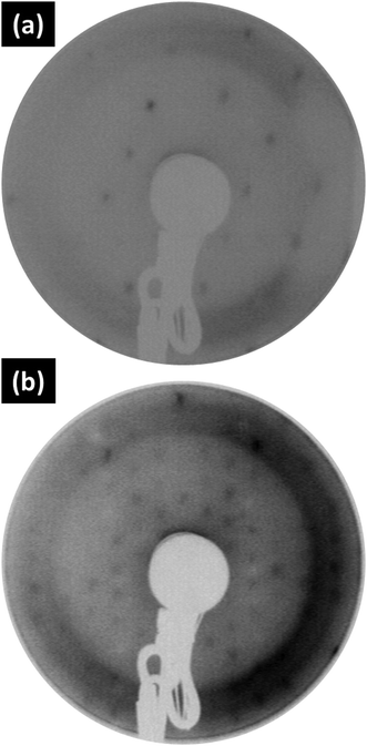
![[1 with combining macron]](https://www.rsc.org/images/entities/char_0031_0304.gif) 0) surface exhibits rhombic symmetry and a simple 1 × 1 diffraction pattern whereas the (0001) surface (with hexagonal symmetry) shows a complex surface reconstruction. (Fig. 2). It was not possible to record LEED patterns of the unannealed surfaces due to a high degree of charging. Atomic force microscopy (AFM) was used to image the topography of the bare surfaces (Fig. S1, ESI†). The unannealed surfaces were found to be less rough than the annealed surfaces, unannealed (2
0) surface exhibits rhombic symmetry and a simple 1 × 1 diffraction pattern whereas the (0001) surface (with hexagonal symmetry) shows a complex surface reconstruction. (Fig. 2). It was not possible to record LEED patterns of the unannealed surfaces due to a high degree of charging. Atomic force microscopy (AFM) was used to image the topography of the bare surfaces (Fig. S1, ESI†). The unannealed surfaces were found to be less rough than the annealed surfaces, unannealed (2![[1 with combining macron]](https://www.rsc.org/images/entities/char_0031_0304.gif)
![[1 with combining macron]](https://www.rsc.org/images/entities/char_0031_0304.gif) 0) (Rq = 65.4 pm) vs. annealed (2
0) (Rq = 65.4 pm) vs. annealed (2![[1 with combining macron]](https://www.rsc.org/images/entities/char_0031_0304.gif)
![[1 with combining macron]](https://www.rsc.org/images/entities/char_0031_0304.gif) 0) (Rq = 82.7 pm). In addition to this the (0001) surfaces were more rough than their (2
0) (Rq = 82.7 pm). In addition to this the (0001) surfaces were more rough than their (2![[1 with combining macron]](https://www.rsc.org/images/entities/char_0031_0304.gif)
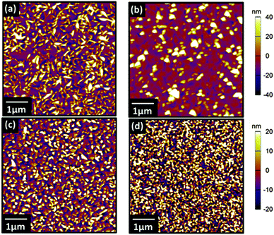
![[1 with combining macron]](https://www.rsc.org/images/entities/char_0031_0304.gif) 0) counterparts, unannealed (0001) (Rq = 77.2 pm) vs. annealed (0001) (Rq = 106.2 pm). Previous work has demonstrated that thin films of VOPc grown on inert substrates held at room temperature exhibit featureless X-ray diffraction patterns.8 To promote crystallinity within VOPc thin films the substrate was therefore held at an elevated temperature of 155 °C during film growth.11,12 This substrate temperature was chosen to match our previous studies of VOPc where highly reproducible crystalline films which can be easily analysed using lab based XRD were produced. On to these substrates thin films of VOPc (50 nm) were evaporated and AFM was used to investigate their morphologies (Fig. 3). All films exhibited similar triangular-grain morphology, with slightly smaller grains evident on the (0001) surfaces. A higher resolution image of these VOPc films on (0001) surfaces can be found in the ESI† (Fig. S3). The disparity in grain size between the VOPc films on the (2
0) counterparts, unannealed (0001) (Rq = 77.2 pm) vs. annealed (0001) (Rq = 106.2 pm). Previous work has demonstrated that thin films of VOPc grown on inert substrates held at room temperature exhibit featureless X-ray diffraction patterns.8 To promote crystallinity within VOPc thin films the substrate was therefore held at an elevated temperature of 155 °C during film growth.11,12 This substrate temperature was chosen to match our previous studies of VOPc where highly reproducible crystalline films which can be easily analysed using lab based XRD were produced. On to these substrates thin films of VOPc (50 nm) were evaporated and AFM was used to investigate their morphologies (Fig. 3). All films exhibited similar triangular-grain morphology, with slightly smaller grains evident on the (0001) surfaces. A higher resolution image of these VOPc films on (0001) surfaces can be found in the ESI† (Fig. S3). The disparity in grain size between the VOPc films on the (2![[1 with combining macron]](https://www.rsc.org/images/entities/char_0031_0304.gif)
![[1 with combining macron]](https://www.rsc.org/images/entities/char_0031_0304.gif) 0) and (0001) surfaces is most likely a result of the differences in surface morphology and roughness. The (2
0) and (0001) surfaces is most likely a result of the differences in surface morphology and roughness. The (2![[1 with combining macron]](https://www.rsc.org/images/entities/char_0031_0304.gif)
![[1 with combining macron]](https://www.rsc.org/images/entities/char_0031_0304.gif) 0) surfaces are less rough than (0001) surfaces and therefore present fewer nucleation sites for VOPc grains which grow larger at the expense of nucleating new crystals.
0) surfaces are less rough than (0001) surfaces and therefore present fewer nucleation sites for VOPc grains which grow larger at the expense of nucleating new crystals.
 | ||
Fig. 3 AFM topography images of 50 nm VOPc films grown on (a) unannealed (2![[1 with combining macron]](https://www.rsc.org/images/entities/char_0031_0304.gif) ![[1 with combining macron]](https://www.rsc.org/images/entities/char_0031_0304.gif) 0) LiNbO3 (b) annealed (2 0) LiNbO3 (b) annealed (2![[1 with combining macron]](https://www.rsc.org/images/entities/char_0031_0304.gif) ![[1 with combining macron]](https://www.rsc.org/images/entities/char_0031_0304.gif) 0) LiNbO3 (c) unannealed (0001) LiNbO3 and (d) annealed (0001) LiNbO3. 0) LiNbO3 (c) unannealed (0001) LiNbO3 and (d) annealed (0001) LiNbO3. | ||
This is exacerbated by the fact that the (0001) surface presents regular terraces which might further promote nucleation (Fig. S2, ESI†).30 As a result the roughness of the VOPc films grown on (0001) surfaces, VOPc/unannealed (0001) (Rq = 12.8 nm) and VOPc/annealed (0001) (Rq = 15.8 nm), is lower than the roughness values for VOPc films grown on the (2![[1 with combining macron]](https://www.rsc.org/images/entities/char_0031_0304.gif)
![[1 with combining macron]](https://www.rsc.org/images/entities/char_0031_0304.gif) 0) surfaces, VOPc/unannealed (2
0) surfaces, VOPc/unannealed (2![[1 with combining macron]](https://www.rsc.org/images/entities/char_0031_0304.gif)
![[1 with combining macron]](https://www.rsc.org/images/entities/char_0031_0304.gif) 0) (Rq = 24.9 nm) and VOPc/annealed (2
0) (Rq = 24.9 nm) and VOPc/annealed (2![[1 with combining macron]](https://www.rsc.org/images/entities/char_0031_0304.gif)
![[1 with combining macron]](https://www.rsc.org/images/entities/char_0031_0304.gif) 0) (Rq = 19.4 nm). Despite these differences in the roughness and grain size within the VOPc films, the overall morphology is very similar.
0) (Rq = 19.4 nm). Despite these differences in the roughness and grain size within the VOPc films, the overall morphology is very similar.
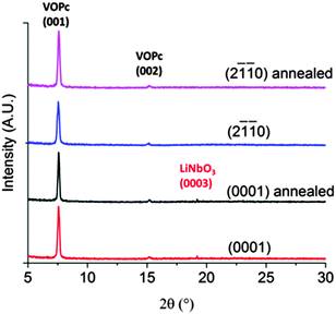
XRD patterns show that all films of VOPc, regardless of in-plane orientation or preparation of lithium niobate, have the same out-of-plane structure. The diffractograms (Fig. 4) show peaks at 2θ = 7.6° and 15.2° which, using our recently redetermined crystal structure of VOPc (CCDC 1017243), correspond to its (001) and (002) planes. The chemical differences of the substrates and differences in direction of the electric field appear to have no effect on the behaviour of the organic molecules deposited on top. In addition, the morphology and out-of-plane structure of these VOPc films are strikingly similar to that of VOPc films grown in the same way on silicon substrates covered with their native oxide (hereafter abbreviated SiO2).8 Despite the prediction of a strong interaction between the surface polarisation and the dipolar molecules, it appears that the ferroelectric surfaces result in the same film growth behaviour as inert and amorphous SiO2 surfaces, and that the lithium niobate could therefore be considered non-interacting. It is also possible that the molecules are adopting a structure based on a strong interaction with the surface, but that the interactions between the VOPc molecules and the (0001) and (2![[1 with combining macron]](https://www.rsc.org/images/entities/char_0031_0304.gif)
![[1 with combining macron]](https://www.rsc.org/images/entities/char_0031_0304.gif) 0) surfaces result in the same film structure. It has been previously found that surfaces with different structures (i.e. Au(111) vs. Au(100))4,5,13,14 or terminations (i.e. in ZnO)15 can strongly affect the properties of phthalocyanine films deposited onto them.
0) surfaces result in the same film structure. It has been previously found that surfaces with different structures (i.e. Au(111) vs. Au(100))4,5,13,14 or terminations (i.e. in ZnO)15 can strongly affect the properties of phthalocyanine films deposited onto them.
A strongly interacting lithium niobate substrate would therefore be expected to lead to different VOPc properties for growth on the (0001) and (2![[1 with combining macron]](https://www.rsc.org/images/entities/char_0031_0304.gif)
![[1 with combining macron]](https://www.rsc.org/images/entities/char_0031_0304.gif) 0) surfaces. Observation of the contrary necessitates the effect of the strong electric field in the (0001) case to exactly compensate those differences, which seems highly unlikely. This then brings into question the nature of the surface electric field and its stability. It has been well documented that the surface polarisation of ferroelectric materials is unstable and as such surface charge may be compensated by a variety of dampening mechanisms.16–18 This can occur through adsorption of ionic species and dipolar molecules, when in ambient conditions, or through a reorganisation of charge carriers within the bulk crystal. As such it seems likely that the surface charge of the lithium niobate has been screened, either extrinsically or intrinsically, and therefore the VOPc molecules are not experiencing the expected electric field effects. Without an interaction between the molecules and this surface polarisation their structure is determined by the interactions between the molecules within the film themselves and not through interactions with the surface, as is the case on an inert substrate such as SiO2. If the surface was ideally bulk truncated and the polarisation preserved interactions between the polarisable V
0) surfaces. Observation of the contrary necessitates the effect of the strong electric field in the (0001) case to exactly compensate those differences, which seems highly unlikely. This then brings into question the nature of the surface electric field and its stability. It has been well documented that the surface polarisation of ferroelectric materials is unstable and as such surface charge may be compensated by a variety of dampening mechanisms.16–18 This can occur through adsorption of ionic species and dipolar molecules, when in ambient conditions, or through a reorganisation of charge carriers within the bulk crystal. As such it seems likely that the surface charge of the lithium niobate has been screened, either extrinsically or intrinsically, and therefore the VOPc molecules are not experiencing the expected electric field effects. Without an interaction between the molecules and this surface polarisation their structure is determined by the interactions between the molecules within the film themselves and not through interactions with the surface, as is the case on an inert substrate such as SiO2. If the surface was ideally bulk truncated and the polarisation preserved interactions between the polarisable V![[double bond, length as m-dash]](https://www.rsc.org/images/entities/char_e001.gif) O bond and substrate dipole may be expected. This may have the effect of modifying the crystalline structure or texture of the VOPc crystallites prepared on the ferroelectric surfaces.
O bond and substrate dipole may be expected. This may have the effect of modifying the crystalline structure or texture of the VOPc crystallites prepared on the ferroelectric surfaces.
Conclusions
The structure of thin films of vanadyl phthalocyanine (VOPc) have been investigated on unannealed and annealed (0001) and (2![[1 with combining macron]](https://www.rsc.org/images/entities/char_0031_0304.gif)
![[1 with combining macron]](https://www.rsc.org/images/entities/char_0031_0304.gif) 0) lithium niobate. X-ray diffraction and atomic force microscopy measurements have shown the structure and morphologies of these thin films to be almost identical, with no dependence on the surface symmetry or the nature of the direction of the surface polarisation. The structure and morphology of these VOPc films is the same as that of identical films on inert silicon dioxide. The nature of ferroelectric materials suggests that this lack of interaction with the surface electric field may be due to dampening caused by charge screening mechanisms. Although the two systems are quite different, this work suggests that the introduction of ferroelectric materials into OPV devices will have little impact on the structure of the organic semiconducting layer.
0) lithium niobate. X-ray diffraction and atomic force microscopy measurements have shown the structure and morphologies of these thin films to be almost identical, with no dependence on the surface symmetry or the nature of the direction of the surface polarisation. The structure and morphology of these VOPc films is the same as that of identical films on inert silicon dioxide. The nature of ferroelectric materials suggests that this lack of interaction with the surface electric field may be due to dampening caused by charge screening mechanisms. Although the two systems are quite different, this work suggests that the introduction of ferroelectric materials into OPV devices will have little impact on the structure of the organic semiconducting layer.
Acknowledgements
We thank Dr Steve Dunn (Queen Mary University of London) and Professor Neil Alford (Imperial College), for useful discussions. AJR and SH acknowledge support from the Engineering and Physical Sciences Research Council (EPSRC), UK (Doctoral Training Centre in Plastic Electronics, Grant no. EP/G037515/1). MPR thanks the EPSRC, UK (Grant no. EP/J500161/1). LSR and TSJ acknowledge support from the EPSRC, UK (Grant no. EP/H021388/1). The underlying data for this manuscript are freely available from the following DOI: 10.6084/m9.figshare.2007915.References
- S. Sanna and W. G. Schmidt, Phys. Rev. B: Condens. Matter Mater. Phys., 2010, 81, 214116 CrossRef.
- R. S. Weis and T. K. Gaylord, Appl. Phys. A: Mater. Sci. Process., 1985, 203, 191–203 CrossRef.
- Y. Wang, K. Wu, J. Kröger and R. Berndt, AIP Adv., 2012, 2, 041402 CrossRef.
- L. A. Rochford, I. Hancox and T. S. Jones, Surf. Sci., 2014, 628, 62–65 CrossRef CAS.
- F. Petraki, H. Peisert, U. Aygül, F. Latteyer, J. Uihlein, A. Vollmer and T. Chassé, J. Phys. Chem. C, 2012, 116, 11110–11116 CAS.
- I. Kröger, B. Stadtmüller, C. Stadler, J. Ziroff, M. Kochler, A. Stahl, F. Pollinger, T. L. Lee, J. Zegenhagen, F. Reinert and C. Kumpf, New J. Phys., 2010, 12, 083038 CrossRef.
- A. C. Cruickshank, C. J. Dotzler, S. Din, S. Heutz, M. F. Toney and M. P. Ryan, J. Am. Chem. Soc., 2012, 134, 14302–14305 CrossRef CAS PubMed.
- A. J. Ramadan, L. A. Rochford, D. S. Keeble, P. Sullivan, M. P. Ryan, T. S. Jones and S. Heutz, J. Mater. Chem. C, 2015, 3, 461–465 RSC.
- S. C. Bharath, K. R. Pimputkar, A. M. Pronschinske and T. P. Pearl, Appl. Surf. Sci., 2008, 254, 2048–2053 CrossRef CAS.
- A. R. McGhie, A. F. Garito and A. J. Heeger, J. Cryst. Growth, 1974, 22, 295–297 CrossRef CAS.
- L. Li, Q. Tang, H. Li and W. Hu, J. Phys. Chem. B, 2008, 112, 10405–10410 CrossRef CAS PubMed.
- F. Pan, H. Tian, X. Qian, L. Huang, Y. Geng and D. Yan, Org. Electron., 2011, 12, 1358–1363 CrossRef CAS.
- D. G. De Oteyza, A. El-Sayed, J. M. Garcia-Lastra, E. Goiri, T. N. Krauss, A. Turak, E. Barrena, H. Dosch, J. Zegenhagen, A. Rubio, Y. Wakayama and J. E. Ortega, J. Chem. Phys., 2010, 133, 214703 CrossRef CAS PubMed.
- T. J. Schuerlein, J. Vac. Sci. Technol., A, 1994, 12, 1992 CAS.
- A. J. Ramadan, L. A. Rochford, M. P. Ryan, T. S. Jones and S. Heutz, RSC Adv., 2015, 5, 65949–65952 RSC.
- Y. Yun, L. Kampschulte, M. Li, D. Liao and E. I. Altman, J. Phys. Chem. C, 2007, 111, 13951–13956 CAS.
- Y. Cui, J. Briscoe and S. Dunn, Chem. Mater., 2013, 25, 4215–4223 CrossRef CAS.
- S. Dunn, D. Tiwari, P. M. Jones and D. E. Gallardo, J. Mater. Chem., 2011, 17, 4460 RSC.
Footnote |
| † Electronic supplementary information (ESI) available: AFM images of bare lithium niobate, AFM images of VOPc on lithium niobate and enhanced resolution XRD pattern. See DOI: 10.1039/c5tc03730a |
| This journal is © The Royal Society of Chemistry 2016 |


