Substituent position engineering of diphenylquinoline-based Ir(III) complexes for efficient orange and white PhOLEDs with high color stability/low efficiency roll-off using a solution-processed emission layer†
Received
20th September 2015
, Accepted 13th November 2015
First published on 13th November 2015
Abstract
Three new heteroleptic Ir(III) complexes o-LIrpic, m-LIrpic, and p-LIrpic (L = CF3DPQ) consisting of 2,4-diphenylquinoline (DPQ) with a –CF3 group at ortho (o)/meta (m)/para (p) positions of the metalated phenyl ring, respectively, as the main ligands were synthesized and used as emitters in phosphorescent organic light-emitting diodes (PhOLEDs). We realized that –CF3 position extremely affects the crucial photophysical and electronic properties such as emission color, photoluminescence quantum yield (PLQY) and energy levels of these Ir(III) complexes resulting in –CF3 position-dependent performance of their PhOLEDs. To verify the effect of –CF3 group position on device performance, three other Ir(III) complexes o-LIrtmd, m-LIrtmd, and p-LIrtmd were synthesized using the same main ligands but a different ancillary ligand. In the two series of Ir(III) complexes, the devices with m-CF3 based complexes are outstanding in performance compared to o- or p-CF3 based ones due to the enhanced PLQY and well suppressed non-radiative deactivations by m-substitution. Finally, the single emission layer solution-processed orange and two-component white PhOLEDs fabricated using m-LIrpic as orange emitter achieved the maximum external quantum efficiency of 17.1% (43.9 cd A−1) and 21.1% (48.8 cd A−1), respectively, with highly stable color coordinates and low efficiency roll-off. This is the highest efficiency reported to date for solution-processed orange PhOLEDs using a small molecular host with easily accessible emitter.
1. Introduction
Highly efficient orange phosphorescent heavy-metal complexes are indispensable for the fabrication of monochromatic displays and two-component or full color white organic light-emitting diodes (WOLEDs).1 Among the heavy-metal complexes, iridium(III) complexes are considered as the most promising phosphors in OLEDs mainly due to their high spin–orbit coupling (SOC) and the ease of functionalization of cyclometalating (C^N) ligands to control the emission colors.2 In recent years, orange phosphorescent OLEDs (PhOLEDs) using Ir(III) complex emitters have achieved a high external quantum efficiency (EQE) of about 28% in vapor deposition processes.3 Conversely, the solution process is the most preferred method due to its low processing cost and large scale application for practical utility.4 But the availability of highly soluble orange Ir(III) complex emitters with easy synthetic routes is scarce and also the efficiencies of their solution-processed PhOLEDs are laid far behind those of the vacuum-deposited ones to date.5 Until now, the highest EQE reported for solution-processed orange PhOLEDs with Ir(III) complex [Ir(Flpy–CF3)3] emitter was 17.6% with Commission Internationale de L'Eclairage (CIE) coordinates (0.531, 0.466).5b However, here a dendrimeric host was used which restricts the usage of higher generation dendrimers due to their voltage-dependent poor carrier mobility. Also the synthesis of the C^N ligand was achieved by multi-steps which limits its application in a large scale.6
2,4-Diphenylquinoline (DPQ)-based C^N ligands are considered as promising candidates for developing efficient orange/orange-red Ir(III) complexes for solution-processed PhOLEDs due to their elevated electron-affinities, ease of synthesis and high solubility without the need of any alkyl chains.7 Based on this, recently we demonstrated a series of solution-processable Ir(III) complexes with different C^N ligands containing a phenylquinoline moiety.7a Amongst them, the orange PhOLEDs with (DPQ)2Ir(pic–N–O) emitter showed a maximum EQE of 14.2% in a ternary host system compared to devices based on other (perfluorinated phenyl-, fluorenyl-, and carbazoyl-phenylquinoline ligand based) Ir(III) complexes owing to its relatively high photoluminescence quantum yield (PLQY), which illustrates the advantage of the DPQ ligand over the other C^N ligands in designing efficient phosphors. On the other hand, the energy levels of the emissive states (3MLCT and/or 3LC) of the Ir(III) complexes can be effectively modified to obtain wide-ranging emission colors and PLQYs by the substituent effects such as electron withdrawing or electron donating on C^N ligands and also by the substituent position effects.2c,7h As far as we know, the fine-tuning of PLQY and photophysical/electronic properties and hence the PhOLED performance of the Ir(III) complexes by a simple control of the substituent position on the C^N ligand has not been much investigated.
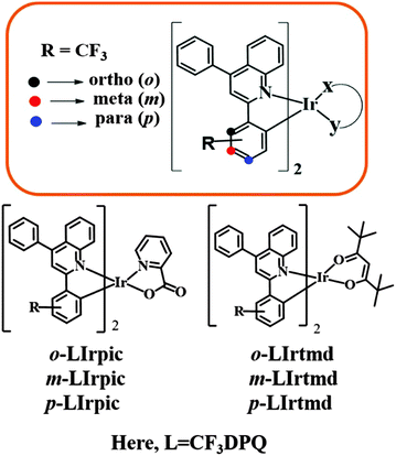
With the aim to develop novel orange Ir(III) complexes that are easy to access synthetically and that possess high PLQY and good solubility for realization of highly efficient solution-processed PhOLEDs in practical applications, we selected DPQ as the C^N ligand driven by its flexible color tunabilitiy. In this paper, we introduced the trifluoromethyl (–CF3) group at ortho (o)/meta (m)/para (p) positions (Fig. 1) of the metalated phenyl ring of DPQ and synthesized Ir(III) complexes with two different ancillary ligands in order to validate the effect of –CF3 position on the electronic structure of the Ir(III) complexes and consequently on the performance of PhOLEDs. We realized that the location of –CF3 is very important in attaining high device performance. In particular, the orange PhOLED fabricated with a solution-processed emission layer using the m-CF3 linked Ir(III) complex, m-LIrpic, as dopant achieved the maximum EQE of 17.1% with CIE coordinates (0.528, 0.469), and this is the highest EQE among the solution-processed orange PhOLEDs using a small molecular host system (see Table S1 of ESI† for a summary of the reported device performance) and also this result is similar to the highest efficiency reported using a dendrimeric host.5b Furthermore, the two-component white PhOLEDs fabricated with m-LIrpic as the orange component demonstrated a maximum EQE of 21.1%. The detailed approach and the results are discussed hereafter.
 |
| | Fig. 1 Structures of the Ir(III) complexes and representation of substituent position. | |
2. Results and discussion
2.1 Synthesis and characterization
The –CF3 functionalized C^N ligands o-L, m-L, and p-L (L = CF3DPQ) based on the DPQ skeleton were prepared in a single step by the acid-catalyzed Friedlander condensation reaction7d of two commercially available starting materials. The new Ir(III) complexes o-LIrpic, m-LIrpic, p-LIrpic and o-LIrtmd, m-LIrtmd, p-LIrtmd were prepared readily following the syntheses of the intermediate dichloro-bridged dimers and the reaction of the corresponding dimer with ancillary ligands picolinate (pic) or 2,2,6,6-tetramethylheptane-3,5-diketonate (tmd) in the presence of Na2CO3 base (Scheme S1, ESI†). All the Ir(III) complexes have been characterized by 1H, 13C NMR, and high resolution mass spectroscopy [Fig. S1 and S2 in ESI†]. The new Ir(III) complexes have good solubility in common organic solvents such as chloroform (CHCl3), tetrahydrofuran, and chlorobenzene (CB).
2.2 Thermal and photophysical properties
The thermal properties of the Ir(III) complexes were evaluated using thermogravimetric analysis (TGA) under a N2 atmosphere with a scanning rate of 10 °C min−1. The TGA curves (Fig. S3a in ESI†) of all the Ir(III) complexes exhibited reasonable thermal stability with decomposition temperatures (Td), corresponding to 5% weight loss, over 300–370 °C.
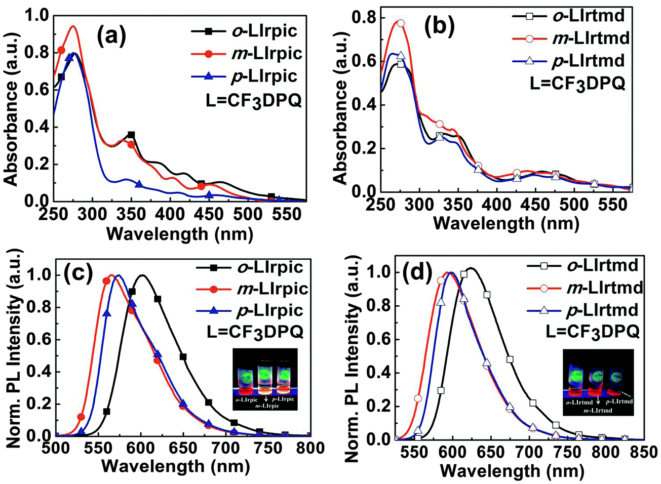
In order to examine the effect of –CF3 group position on the ground and excited state properties of the Ir(III) complexes, UV-visible absorption (Fig. 2a and b) and photoluminescence (PL) spectra (Fig. 2c and d) were measured in CHCl3 (10−5 M) at room temperature. The stronger absorption peaks between 265 and 350 nm mostly represent the ligand centered 1π–π* transitions. The weaker absorption peaks between 350 and 520 nm are known to be the admixed 1MLCT and 3MLCT/3LC transitions where the usually spin-forbidden transitions of the triplet states are allowed due to the strong SOC induced by the iridium metal.8 As shown in Fig. 2a and b, the lower energy transition bands of m-LIrpic and m-LIrtmd are clearly blue shifted compared to the o- and p-analogs indicating the impact of –CF3 substitution position on the ground state properties of the Ir(III) complexes.
 |
| | Fig. 2 (a and b) UV-visible absorption spectra; (c and d) PL spectra of the Ir(III) complexes in CHCl3 solution [Insets are photographs of emission color upon UV-irradiation]. | |
Insets in Fig. 2c and d represent emission colors of the Ir(III) complexes after UV-irradiation in CHCl3. All the Ir(III) complexes emit an intense orange/orange-red/red color upon photo-excitation. The structureless emission pattern of these Ir(III) complexes indicates the 3MLCT character of the emissive excited state.9 The position of –CF3 on DPQ has marked changes in the emission wavelengths of both the series of Ir(III) complexes. The PL peaks are recorded at 602, 565, 574 nm and 623, 593, 598 nm for o-LIrpic, m-LIrpic, p-LIrpic and o-LIrtmd, m-LIrtmd, p-LIrtmd, respectively. Similar to the lower energy bands in the absorption spectra, the PLmax of m-LIrpic is hypsochromically shifted around 37 nm and 9 nm compared to the o-LIrpic and p-LIrpic, respectively. The –CF3 group at m-location lowers the highest occupied molecular orbital (HOMO) level of m-LIrpic leading to blue shift in emission.10,11 The strong polarization effect and the large steric volume of the –CF3 substituent at o-position might be further reasons for variation in the electronic distribution of o-LIrpic when compared to p-LIrpic.12 Similar tendencies in PL were also observed for o-LIrtmd, m-LIrtmd, and p-LIrtmd demonstrating the influence of –CF3 group position on emission color tuning.
As shown in Fig. S3b (ESI†), the trends in film state emission spectra of all the Ir(III) complexes were comparable to those measured in CHCl3 except that the former are red shifted about 12–25 nm in the case of o-LIrpic, m-LIrpic, p-LIrpic and 4–7 nm in o-LIrtmd, m-LIrtmd, p-LIrtmd. The well-known reason for the less red shift in tmd based Ir(III) complexes is the bulky tBu groups which suppress the intermolecular interactions responsible for bathochromic shift in solid state emission.13 The PLQYs of o-LIrpic, m-LIrpic, p-LIrpic and o-LIrtmd, m-LIrtmd, p-LIrtmd are 0.27, 0.65, 0.57 and 0.18, 0.41, 0.37, respectively, measured in dichloromethane (CH2Cl2) at room temperature using rhodamine B (Φf = 0.68) as a standard. The transient PL analyses were carried out for estimating the emission lifetimes of the Ir(III) complexes in CH2Cl2 at room temperature and in 2-methyltetrahydrofuran (2-MeTHF) at 77 K (Fig. S4, ESI† and Table 1). The decay profiles of all the Ir(III) complexes are monoexponential with short emission lifetimes ranging from 2.0 to 2.5 μs for o-LIrpic, m-LIrpic, p-LIrpic and from 1.6 to 2.0 μs for o-LIrtmd, m-LIrtmd, p-LIrtmd in CH2Cl2 representing phosphorescence as the origin of emission.14 In order to gain insight into the root cause for variation in PLQYs of the Ir(III) complexes, the relaxation dynamics such as radiative and non-radiative decay rate constants (Kr/Knr) were calculated from the obtained lifetimes. In accordance with the energy gap law,15 the m-CF3 based Ir(III) complexes exhibited relatively low Knr and high PLQYs compared to the o- or p-CF3 based Ir(III) complexes for both the series demonstrating the substituent position effect on the emissive properties of the Ir(III) complexes.
Table 1 Thermal, photophysical, and electrochemical properties of the Ir(III) complexes
| Ir(III) complex |
T
d [°C] |
λ
em
[nm] |
PLQYb,c |
K
r
[105 s−1] |
K
nr
[105 s−1] |
τ
,
[μs] |
E
g
[eV] |
HOMOf/LUMOg [eV] |
|
Measured in CHCl3 solution at room temperature (1 × 10⁻⁵ M).
Rhodamine B (ϕpl = 0.68) in 94% ethanol is used as reference.
Measured in CH2Cl2 at room temperature.
Excited state lifetimes.
Optical band gaps.
Calculated from CV.
Deduced from HOMO and Eg.
|
|
o-LIrpic
|
302 |
602 |
0.27 |
1.23 |
3.32 |
2.2 |
2.09 |
−5.50/−3.41 |
|
m-LIrpic
|
362 |
565 |
0.65 |
2.60 |
1.40 |
2.5 |
2.35 |
−5.65/−3.30 |
|
p-LIrpic
|
370 |
574 |
0.57 |
2.85 |
2.15 |
2.0 |
2.17 |
−5.53/−3.36 |
|
o-LIrtmd
|
364 |
623 |
0.18 |
1.13 |
5.13 |
1.6 |
1.88 |
−5.28/−3.40 |
|
m-LIrtmd
|
349 |
593 |
0.41 |
2.05 |
2.95 |
2.0 |
2.17 |
−5.41/−3.24 |
|
p-LIrtmd
|
335 |
598 |
0.37 |
1.95 |
3.32 |
1.9 |
2.06 |
−5.33/−3.27 |
2.3 Electrochemical and theoretical calculations
Cyclic voltammetry (CV) measurements were carried out to study the –CF3 group position effect on the redox properties and subsequently on the frontier orbitals of the six Ir(III) complexes. As depicted in Fig. S5 (ESI†), the oxidation potentials of m-CF3 complexes are positive-shifted in comparison with o- and p-CF3 analogs. As a result, the HOMO levels of m-based Ir(III) complexes are noticeably stabilized (see Table 1) causing the enhancement in band gaps. The CV characteristics of all the Ir(III) complexes are in good agreement with the photophysical properties. Hence, it is worth noting that a change in the location of –CF3 does affect the redox properties of these Ir(III) complexes. In order to gain insight into the structure–property relationships, density functional theory (DFT) calculations for all the Ir(III) complexes were carried out and the optimized HOMOs and LUMOs of these Ir(III) complexes are shown in Fig. S6 (ESI†). Throughout the six Ir(III) complexes, the delocalization of HOMOs was mostly distributed over the Ir(III) metal center and the metalated phenyl ring of DPQ, whereas the LUMOs were mostly located on quinoline and partly on both the phenyl rings of the C^N ligands.
2.4 Electroluminescent properties of PhOLEDs
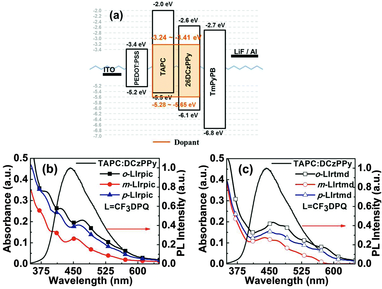
With the aim to elucidate the –CF3 group position effect on EL properties of the new Ir(III) complexes, monochromatic PhOLEDs were fabricated using the following optimized device configuration: ITO/PEDOT:PSS (40 nm)/TAPC:DCzPPy:emitter (10 wt%, 40 nm)/TmPyPB (50 nm)/LiF (1 nm)/Al (100 nm), where TAPC is 1,1-bis(4-methylphenyl)-aminophenyl-cyclohexane, DCzPPy is 2,6-bis(3-(carbazol-9-yl)phenyl)pyridine, and TmPyPB is 1,3,5-tris(m-pyrid-3-ylphenyl)benzene. In all the devices, TAPC:DCzPPy acts as a mixed host, PEDOT:PSS serves as the hole injection layer (HIL), TmPyPB as the electron transport layer (ETL), indium-tin oxide (ITO) as anode and LiF/Al as the electron injection layer and cathode. Device structure and the energy levels of the materials involved in the fabrication of monochromatic PhOLEDs are given in Fig. 3a. Confinement of the excitons in the emitting layer (EML) is expected since the triplet energy (T1)16 of TAPC (T1 = 2.87 eV) and DCzPPy (T1 = 2.71 eV) is higher than that of all the Ir(III) complexes (T1 ∼ 2.08–2.21 eV, see Fig. S7a, ESI†). TAPC is a unipolar (hole transporting) and DCzPPy a bipolar (more electron transporting, less hole transporting) material. Therefore, the molar ratio of TAPC![[thin space (1/6-em)]](https://www.rsc.org/images/entities/char_2009.gif) :DCzPPy was optimized to 4:6 for better charge balance. The EML was spin coated using CB solvent and ETL, LiF and Al were vacuum deposited on top of it. The PL spectra of neat TAPC, DCzPPy, and TAPC:DCzPPy films are given in Fig. S7b (ESI†). As demonstrated in Fig. 3b and c, the deep overlap of the emission spectrum of TAPC:DCzPPy with the MLCT absorption region of all Ir(III) complexes ensures an efficient energy transfer from the mixed host to the Ir(III) complexes.17
:DCzPPy was optimized to 4:6 for better charge balance. The EML was spin coated using CB solvent and ETL, LiF and Al were vacuum deposited on top of it. The PL spectra of neat TAPC, DCzPPy, and TAPC:DCzPPy films are given in Fig. S7b (ESI†). As demonstrated in Fig. 3b and c, the deep overlap of the emission spectrum of TAPC:DCzPPy with the MLCT absorption region of all Ir(III) complexes ensures an efficient energy transfer from the mixed host to the Ir(III) complexes.17
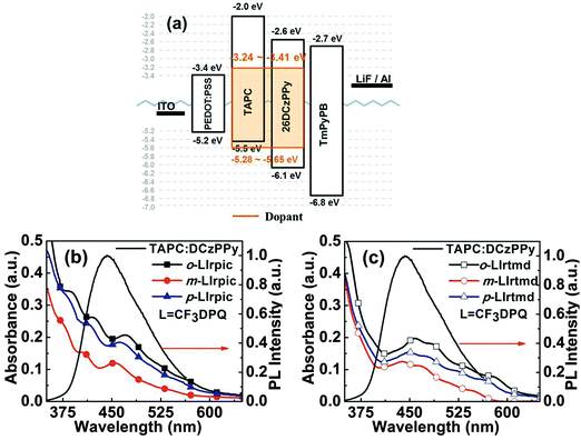 |
| | Fig. 3 (a) Device structure of monochromatic PhOLEDs; (b and c) representation of energy transfer from the host to dopants (PL spectrum of TAPC:DCzPPy and absorption spectra of Ir(III) complexes in the film state). | |
The surface morphology for thin films of the mixed host (TAPC:DCzPPy) and TAPC:DCzPPy doped with 10 wt% Ir(III) complex was analyzed using atomic force microscopy (AFM). As shown in Fig. S8 (ESI†), the root-mean-square (RMS) surface roughness of the doped EML films was similar to that of the undoped TAPC:DCzPPy films and even better in the case of m-LIrpic and m-LIrtmd doped films. The current density–voltage–luminance (J–V–L) and EQE–luminance (η–L) of the PhOLEDs based on o-LIrpic, m-LIrpic, and p-LIrpic dopants are represented in Fig. 4a and b. The maximum luminance of the devices is 1592 cd m−2 for o-LIrpic, 4062 cd m−2 for m-LIrpic, and 3710 cd m−2 for p-LIrpic. The highest EQE of 17.1% (43.9 cd A−1, 23.0 lm W−1) was demonstrated by the PhOLED with m-LIrpic, while the p-LIrpic and o-LIrpic showed 12.8% (30.1 cd A−1, 13.5 lm W−1) and 8.9% (13.2 cd A−1, 5.2 lm W−1), respectively. Furthermore, a low efficiency roll-off was recorded for the m-LIrpic based device with an EQE of about 14.7% at 1000 cd m−2, i.e. efficiency is retained up to 86%. The results of the monochromatic PhOLEDs are summarized in Table 2. The device architecture also has an important role in the high performance of m-LIrpic along with its good photophysical properties. It could be explained by considering the HOMO levels of these Ir(III) complexes where a moderate barrier of 0.15 eV exists for hole transfer from the TAPC to the m-LIrpic, while the remaining complexes do not have any such barrier. It is well known that the electron mobility in organic materials is generally several orders of magnitude lower than the hole mobility.18 From this, we strongly believe that the moderate hole barrier of m-LIrpic [0.15 eV] balances the injection of holes in line with electrons, and therefore, a high recombination of hole–electron is anticipated. In addition, introduction of –CF3 at m-position highly suppressed the non-radiative deactivations and improved the PLQY of the m-CF3 based complexes which resulted in high efficiency in PhOLEDs.
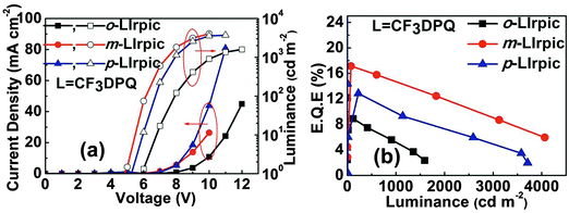 |
| | Fig. 4 (a) Current density–voltage–luminance (J–V–L); (b) EQE–luminance (η–L) characteristics of monochromatic PhOLEDs with o-LIrpic, m-LIrpic, and p-LIrpic. | |
Table 2 EL characteristics of monochromatic PhOLEDs with the new Ir(III) complexes
| Dopant |
Maximum device performance |
At 1000 cd m−2 |
ELmaxa [nm] |
CIEa [x, y] |
| EQE [%] |
PE [lm W−1] |
LE [cd A−1] |
EQE [%] |
PE [lm W−1] |
LE [cd A−1] |
|
Values collected at a current density of 30 mA cm−2.
|
|
o-LIrpic
|
8.9 |
5.2 |
13.2 |
5.2 |
2.4 |
7.8 |
602 |
(0.613, 0.383) |
|
m-LIrpic
|
17.1 |
23.0 |
43.9 |
14.8 |
16.5 |
38.0 |
572 |
(0.528, 0.469) |
|
p-LIrpic
|
12.8 |
13.5 |
30.1 |
9.9 |
9.3 |
23.1 |
580 |
(0.556, 0.441) |
|
o-LIrtmd
|
3.7 |
1.2 |
3.0 |
1.9 |
0.5 |
1.7 |
629 |
(0.663, 0.336) |
|
m-LIrtmd
|
6.4 |
5.5 |
11.3 |
5.8 |
4.4 |
10.3 |
597 |
(0.593, 0.405) |
|
p-LIrtmd
|
5.0 |
3.4 |
7.5 |
4.4 |
2.7 |
6.7 |
602 |
(0.622, 0.377) |
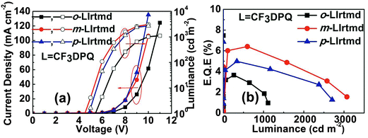
In order to validate the aforementioned effect of –CF3 group position on device performance, PhOLEDs with another series of emitters o-LIrtmd, m-LIrtmd, and p-LIrtmd containing tmd ancillary ligand were fabricated using a similar device configuration. Fig. 5a and b represent the J–V–L and η–L plots of the PhOLEDs with these Ir(III) complexes. Though the device structure and the main ligands are the same, the performance of o-LIrpic, m-LIrpic, and p-LIrpic based devices is outstanding compared to the o-LIrtmd, m-LIrtmd, and p-LIrtmd based devices. It is beyond the scope of this paper to examine the exact reasons for the low performance of ‘tmd’ based PhOLEDs; however, it could be partly due to the low PLQY of these Ir(III) complexes. Interestingly, the trends in the efficiency of o-LIrtmd, m-LIrtmd, and p-LIrtmd based devices follow the structure–property relationships similar to the o-LIrpic, m-LIrpic, and p-LIrpic. Accordingly, the PhOLEDs with m-LIrtmd show superior EQE of 6.4% (11.3 cd A−1, 5.5 lm W−1) compared to those based on p-LIrtmd with 5.0% (7.5 cd A−1, 3.4 lm W−1) and o-LIrtmd with 3.7% (3.0 cd A−1, 1.2 lm W−1). In this scenario, it is worth stating that a subtle change in the substituent (–CF3) position on DPQ has a profound impact on the PhOLED device performance.
 |
| | Fig. 5 (a) Current density–voltage–luminance (J–V–L); (b) EQE–luminance (η–L) characteristics of monochromatic PhOLEDs with o-LIrtmd, m-LIrtmd, and p-LIrtmd. | |
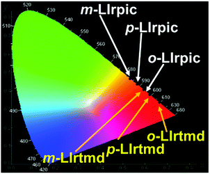
EL spectra of the six PhOLEDs at 30 mA cm−2 are shown in Fig. S9 (ESI†). Though the bandwidths are broadened in the EL spectra, the ELmax are comparable to their PLmax. These variations in the spectral bandwidth of EL compared with PL are expected to be caused by the difference in the excitation process of the Ir(III) complexes.19 The absence of any residual emission from TAPC:DCzPPy in the EL spectra of the devices implies an effective energy transfer from the mixed host to the Ir(III) complexes. The CIE coordinates of the monochromatic PhOLEDs are represented in Fig. 6 and these are (0.624, 0.375), (0.535, 0.461), (0.566, 0.432) for o-LIrpic, m-LIrpic, p-LIrpic and (0.664, 0.334), (0.596, 0.403), (0.622, 0.377) for o-LIrtmd, m-LIrtmd, p-LIrtmd, respectively, at 30 mA cm−2. The confinement of the recombination zone to the EML and the charge balance in the mixed host system are well indicated by the stable CIE coordinates of the PhOLEDs where the shift is just (0.001, 0.001) with increasing luminance as shown in Fig. S10 (ESI†).20 From the above data, it is interesting that the PhOLEDs with m-LIrpic and p-LIrpic show orange color, m-LIrtmd shows orange-red, o-LIrpic and p-LIrtmd show red color, and o-LIrtmd shows deep-red color.
 |
| | Fig. 6 1931 Commission Internationale de L'Eclairage (CIE) coordinates of monochromatic PhOLEDs at 30 mA cm−2. | |
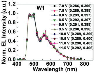
From the high performance of m-LIrpic based orange and [(dfpmpy)2Ir(EO2-pic)] based blue PhOLEDs,21 it is likely that one can attain high efficiency in solution-processed white OLEDs using these materials as two-component emitters. Therefore, we fabricated white PhOLEDs with a single EML using the ternary host system consisting of poly(vinylcarbazole) (PVK)/N,N-dicarbazolyl-3,5-benzene (mCP)/2,2′-(1,3-phenylene)bis[5-(4-tert-butylphenyl)-1,3,4-oxadiazole] (OXD-7) with the following configuration (see Fig. S11, ESI†): ITO/PEDOT:PSS-4083 (40 nm)/PVK:mCP:OXD-7 (37.5:37.5:25) (85 wt%):blue:orange (x:y) (15 wt%) (50 nm)/1,3,5-tri(1-phenyl-1H-benzo[d]imidazol-2-yl)phenyl (TPBi) (30 nm)/LiF (1 nm)/Al (100 nm), where the doping ratios of blue:orange were systematically optimized to 17:0.01 (device W1) and 17:0.015 (device W2). W1 demonstrated a maximum EQE of 21.1% at 2000 cd m−2 with a peak luminance of 12992 cd m−2, and also it exhibited low roll-off in efficiency with EQE 17.3% at 3000 cd m−2 (Fig. 7). Very importantly, the color coordinates of W1 are highly stable with ΔCIEx,y (0.007, 0.009), which is nearly independent of the driving voltage as shown in Fig. 8. All the data of white PhOLEDs are summarized in Table 3, Fig. 7 and Fig. S12 (ESI†). Exchange of the HIL from PEDOT:PSS-4083 to the low conductivity PEDOT:PSS-8000 might have a great potential for further enhancement of device performance due to the improved charge balance.5b,22 In conclusion, to the best of our knowledge, single EML white PhOLEDs fabricated by the solution process having high EQE with very low roll-off up to 3000 cd m−2 and simultaneously possessing ultra-high color stability are seldom reported.23,5b Finally, it is worth stating that both the orange and white PhOLEDs fabricated with the orange phosphor m-LIrpic exhibited an excellent device performance in two separate host systems credited to the good photophysical properties and solution processability of the new orange emitter.
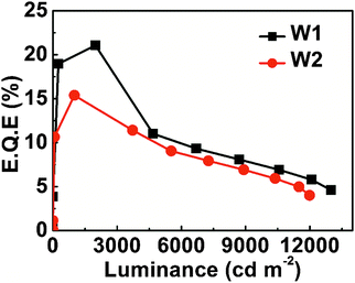 |
| | Fig. 7 EQE–luminance (η–L) characteristics of white PhOLEDs. | |
 |
| | Fig. 8 EL spectra of white PhOLED at different driving voltages. | |
Table 3 EL characteristics of two-component white PhOLEDs with (dfpmpy)2Ir(EO2-pic) [blue] and m-LIrpic [orange]
| Dopant [B:O] |
Maximum device performance |
At 3000 cd m−2 |
L
max [cd m−2] |
CIEa [x, y] |
| EQE [%] |
PE [lm W−1] |
LE [cd A−1] |
EQE [%] |
PE [lm W−1] |
LE [cd A−1] |
|
Values collected at a current density of 30 mA cm−2.
|
| 17:0.01 (W1) |
21.1 |
18.1 |
48.8 |
17.3 |
15.0 |
40.4 |
12992 |
(0.293, 0.395) |
| 17:0.015 (W2) |
15.4 |
13.4 |
36.1 |
12.5 |
10.8 |
29.5 |
11990 |
(0.300, 0.406) |
3. Conclusion
In this work, we introduced a –CF3 group at three different positions (o-/m-/p-) on the 2,4-diphenylquinoline (DPQ) cyclometalating ligand and synthesized two series of highly soluble new heteroleptic Ir(III) complexes o-LIrpic, m-LIrpic, p-LIrpic and o-LIrtmd, m-LIrtmd, p-LIrtmd for usage in solution-processed PhOLEDs. We observed that introduction of –CF3 into m-position greatly diminished the non-radiative relaxations and improved the PLQY of the m-CF3 based Ir(III) complexes and also tuned the emission color from red to orange. As a result, the performance of monochromatic PhOLEDs with both the series of Ir(III) complexes follows the order m > p > o. Particularly, the orange PhOLEDs fabricated with the solution-processed emission layer using m-LIrpic as dopant in a simple mixed host achieved the maximum efficiency of 17.1% with low efficiency roll-off and almost constant CIE coordinates (0.528, 0.469). Furthermore, the two-component white PhOLEDs using m-LIrpic as orange emitter showed a peak EQE of 21.1% with strikingly low efficiency roll-off with 17.3% at 3000 cd m−2 and highly stable color with ΔCIEx,y (0.007, 0.009). The overall results of these orange and white PhOLEDs are among the best ones in solution-processed devices. These findings demonstrate a simple approach for fine-tuning the emissive properties of the Ir(III) complexes in order to obtain highly efficient PhOLEDs for practical application of the solution process.
Acknowledgements
This work was supported by a grant funded by the National Research Foundation (NRF) (2011-0028320) and the Pioneer Research Center Program through the NRF (2013M3C1A3065522) by the Ministry of Science, ICT & Future Planning (MSIP) of Korea.
References
-
(a) S. Reineke, M. Thomschke, B. Lüssem and K. Leo, Rev. Mod. Phys., 2013, 85, 1245 CrossRef CAS;
(b) C. Fan, L. Zhu, B. Jiang, Y. Li, F. Zhao, D. Ma, J. Qin and C. Yang, J. Phys. Chem. C, 2013, 117, 19134 CrossRef CAS;
(c) C.-C. Chen, H.-Y. Lin, C.-H. Li, J.-H. Wu, Z.-Y. Tu, L.-L. Lee, M.-S. Jeng, C.-C. Lin, J.-H. Jou and H.-C. Kuo, Int. J. Photoenergy, 2014, 6 Search PubMed , article ID 851371.
-
(a) Y. H. Lee, J. Park, S.-J. Jo, M. Kim, J. Lee, S. U. Lee and M. H. Lee, Chem. – Eur. J., 2015, 21, 2052 CrossRef CAS PubMed;
(b) D. Liu, H. Ren, L. Deng and T. Zhang, ACS Appl. Mater. Interfaces, 2013, 5, 4937 CrossRef CAS PubMed;
(c) Q.-L. Xu, X. Liang, S. Zhang, Y.-M. Jing, X. Liu, G.-Z. Lu, Y.-X. Zheng and J.-L. Zuo, J. Mater. Chem. C, 2015, 3, 3694 RSC.
-
(a) G. Li, Y. Feng, T. Peng, K. Ye, Y. Liu and Y. Wang, J. Mater. Chem. C, 2015, 3, 1452 RSC;
(b) G. Li, D. Zhu, T. Peng, Y. Liu, Y. Wang and M. R. Bryce, Adv. Funct. Mater., 2014, 24, 7420 CrossRef CAS;
(c) R. Wang, D. Liu, H. Ren, T. Zhang, H. Yin, G. Liu and J. Li, Adv. Mater., 2011, 23, 2823 CrossRef CAS PubMed;
(d) H.-H. Chou, Y.-K. Li, Y.-H. Chen, C.-C. Chang, C.-Y. Liao and C.-H. Cheng, ACS Appl. Mater. Interfaces, 2013, 5, 6168 CrossRef CAS PubMed.
-
(a) X. Liu, S. Wang, B. Yao, B. Zhang, C.-L. Ho, W.-Y. Wong, Y. Cheng and Z. Xie, Org. Electron., 2015, 21, 1 CrossRef CAS;
(b) R. Wang, D. Liu, R. Zhang, L. Deng and J. Li, J. Mater. Chem., 2012, 22, 1411 RSC;
(c) T. Giridhar, T.-H. Han, W. Cho, C. Saravanan, T.-W. Lee and S.-H. Jin, Chem. – Eur. J., 2014, 20, 8260 CrossRef CAS PubMed.
-
(a) K. S. Yook and J. Y. Lee, Adv. Mater., 2014, 26, 4218 CrossRef CAS PubMed;
(b) B. Zhang, G. Tan, C.-S. Lam, B. Yao, C.-L. Ho, L. Liu, Z. Xie, W.-Y. Wong, J. Ding and L. Wang, Adv. Mater., 2012, 24, 1873 CrossRef CAS PubMed;
(c) C. Fan and C. Yang, Chem. Soc. Rev., 2014, 43, 6439 RSC;
(d) H. Xu, R. Chen, Q. Sun, W. Lai, Q. Su, W. Huang and X. Liu, Chem. Soc. Rev., 2014, 43, 3259 RSC;
(e) C.-L. Ho, W.-Y. Wong, G.-J. Zhou, B. Yao, Z. Xie and L. Wang, Adv. Funct. Mater., 2007, 17, 2925 CrossRef CAS;
(f) C. Fan, J. Miao, B. Jiang, C. Yang, H. Wu, J. Qin and Y. Cao, Org. Electron., 2013, 14, 3392 CrossRef CAS.
-
(a) D. A. Markelov, Y. Y. Gotlib, A. A. Darinskii, A. V. Lyulin and S. V. Lyulin, Polym. Sci., Ser. A, 2009, 51, 331 CrossRef;
(b) J. M. Lupton, I. D. W. Samuel, R. Beavington, M. J. Frampton, P. L. Burn and H. Bässler, Phys. Rev. B: Condens. Matter Mater. Phys., 2001, 63, 155206 CrossRef.
-
(a) J. Park, J.-S. Park, Y. G. Park, J. Y. Lee, J. W. Kang, J. Liu, L. Dai and S.-H. Jin, Org. Electron., 2013, 14, 2114 CrossRef CAS;
(b) J. Ding, J. Lü, Y. Cheng, Z. Xie, L. Wang, X. Jing and F. Wang, Adv. Funct. Mater., 2008, 18, 2754 CrossRef CAS;
(c) Z. Ma, J. Ding, B. Zhang, C. Mei, Y. Cheng, Z. Xie, L. Wang, X. Jing and F. Wang, Adv. Funct. Mater., 2010, 20, 138 CrossRef CAS;
(d) S.-J. Lee, J.-S. Park, M. Song, I. A. Shin, Y.-I. Kim, J. W. Lee, J.-W. Kang, Y.-S. Gal, S. Kang, J. Y. Lee, S.-H. Jung, H.-S. Kim, M.-Y. Chae and S.-H. Jin, Adv. Funct. Mater., 2009, 19, 2205 CrossRef CAS;
(e) R. Pode, S.-J. Lee, S.-H. Jin, S. Kim and J. H. Kwon, J. Phys. D: Appl. Phys., 2010, 43, 025101 CrossRef;
(f) M. Song, J. S. Park, M. Yoon, A. J. Kim, Y. I. Kim, Y.-S. Gal, J. W. Lee and S.-H. Jin, J. Organomet. Chem., 2011, 696, 2122 CrossRef CAS;
(g) J. Ding, J. Gao, Q. Fu, Y. Cheng, D. Ma and L. Wang, Synth. Met., 2005, 155, 539 CrossRef CAS;
(h) X. Zhang, J. Gao, C. Yang, L. Zhu, Z. Li, K. Zhang, J. Qin, H. You and D. Ma, J. Organomet. Chem., 2006, 691, 4312 CrossRef CAS.
-
(a) H. J. Bae, J. Chung, H. Kim, J. Park, K. M. Lee, T.-W. Koh, Y. S. Lee, S. Yoo, Y. Do and M. H. Lee, Inorg. Chem., 2014, 53, 128 CrossRef CAS PubMed;
(b) H. K. Dahule, S. J. Dhoble, J.-S. Ahn and R. Pode, J. Phys. Chem. Solids, 2011, 72, 1524 CrossRef CAS.
- C.-Y. Sun, X.-L. Wang, X. Zhang, C. Qin, P. Li, Z.-M. Su, D.-X. Zhu, G.-G. Shan, K.-Z. Shao, H. Wu and J. Li, Nat. Commun., 2013, 4, 2717, DOI:10.1038/ncomms3717.
-
(a) T. Kim, H. Kim, K. M. Lee, Y. S. Lee and M. H. Lee, Inorg. Chem., 2013, 52, 160 CrossRef CAS PubMed;
(b) S.-J. Yun, H.-J. Seo, M. Song, S.-H. Jin, S. K. Kang and Y.-I. Kim, J. Organomet. Chem., 2013, 724, 244 CrossRef CAS.
- J. Frey, B. F. E. Curchod, R. Scopelliti, I. Tavernelli, U. Rothlisberger, M. K. Nazeeruddin and E. Baranoff, Dalton Trans., 2014, 43, 5667 RSC.
-
(a) J. Wang, X. Xu, Y. Tian, C. Yao and L. Li, J. Mater. Chem. C, 2014, 2, 5036 RSC;
(b)
R. D. Chambers, Organofluorine Chemistry: Fluorinated Alkenes and Reactive Intermediates, 1997, vol. 192 Search PubMed.
- D. H. Kim, N. S. Cho, H.-Y. Oh, J. H. Yang, W. S. Jeon, J. S. Park, M. C. Suh and J. H. Kwon, Adv. Mater., 2011, 23, 2721 CrossRef CAS PubMed.
- C.-H. Yang, M. Mauro, F. Polo, S. Watanabe, I. Muenster, R. Fröhlich and L. D. Cola, Chem. Mater., 2012, 24, 3684 CrossRef CAS.
-
(a) X. Cao, J. Miao, M. Zhu, C. Zhong, C. Yang, H. Wu, J. Qin and Y. Cao, Chem. Mater., 2015, 27, 96 CrossRef CAS;
(b) S. Okada, K. Okinaka, H. Iwawaki, M. Furugori, M. Hashimoto, T. Mukaide, J. Kamatani, S. Igawa, A. Tsuboyama, T. Takiguchi and K. Ueno, Dalton Trans., 2005, 1583 RSC.
-
(a) H. Sasabe and J. Kido, Chem. Mater., 2011, 23, 621 CrossRef CAS;
(b) Y.-J. Pu, G. Nakata, F. Satoh, H. Sasabe, D. Yokoyama and J. Kido, Adv. Mater., 2012, 24, 1765 CrossRef CAS PubMed;
(c) J. S. Park, J. H. Yu, W. S. Jeon, Y. H. Son, C. Kulshreshtha and J. H. Kwon, J. Inf. Disp., 2011, 12, 51 CrossRef CAS.
- J. W. Kim, S. I. You, N. H. Kim, J.-A. Yoon, K. W. Cheah, F. R. Zhu and W. Y. Kim, Sci. Rep., 2014, 4, 7009, DOI:10.1038/srep07009.
-
H. Yersin, Highly efficient OLEDs with Phosphorescent Materials, WILEY-VCH Verlag GmbH & Co., 2008, p. 395 Search PubMed.
- C.-H. Fan, P. Sun, T.-H. Su and C.-H. Cheng, Adv. Mater., 2011, 23, 2981 CrossRef CAS PubMed.
- J.-H. Lee, G. Sarada, C.-K. Moon, W. Cho, K.-H. Kim, Y. G. Park, J. Y. Lee, S.-H. Jin and J.-J. Kim, Adv. Opt. Mater., 2015, 3, 211 CrossRef CAS.
- W. Cho, G. Sarada, J.-S. Park, Y.-S. Gal, J. H. Lee and S.-H. Jin, Org. Electron., 2014, 15, 2328 CrossRef CAS.
- C. Fan, Y. Li, C. Yang, H. Wu, J. Qin and Y. Cao, Chem. Mater., 2012, 24, 4581 CrossRef CAS.
- S. Wang, B. Zhang, X. Wang, J. Ding, Z. Xie and L. Wang, Adv. Opt. Mater., 2015, 3, 1349 CrossRef CAS.
Footnotes |
| † Electronic supplementary information (ESI) available. See DOI: 10.1039/c5tc03004h |
| ‡ These authors contributed equally to this work. |
|
| This journal is © The Royal Society of Chemistry 2016 |
Click here to see how this site uses Cookies. View our privacy policy here.