 Open Access Article
Trends in electrode development for next generation solid oxide fuel cells
Wang Hay
Kan†
ab,
Alfred Junio
Samson†
b and
Venkataraman
Thangadurai
*b
aChina Spallation Neutron Source, Institute of High Energy Physics, Chinese Academy of Sciences, Dongguan Institute of Neutron Science, Dongguan, China 523803
bUniversity of Calgary, 2500 University Dr. NW, Calgary, Alberta, Canada T2N 1N4. E-mail: vthangad@ucalgary.ca
First published on 10th November 2016
Abstract
High temperature electrochemical devices, such as solid oxide fuel cells (SOFCs), will play a vital role in the future green and sustainable energy industries due to direct utilization of carbon-based fuels and their ability to couple with renewable energies to convert by-products into valuable fuels using solid oxide electrolysis cells (SOECs). All-solid-state design provides a great opportunity toward the optimization of durability, cost, efficiency and robustness. Electrodes, one of the most important components that facilitate the electrochemical redox reactions, have been actively investigated for several decades to optimize a matrix of chemical composition, microstructure, and performance. Although some mixed ionic electronic conductors (MIECs) can provide electrochemically active surface with excellent chemical tolerance comparing to the composite electrodes made of conventional ceramic electrolyte and metal (cermet), their electrochemical activities may not be high enough to obtain a desirable power, even at moderate temperature operation. This shortage could be improved by engineering the microstructure of the electrodes, which control electrochemically active sites in SOFCs and SOECs. In this article, the current trends in electrode-engineering techniques for advanced SOFCs are reviewed.
1. Introduction
The ever-growing concern over the availability of fossil fuel resources and the unpredictably adverse climatic conditions have driven many countries to attempt to decrease greenhouse gas emissions and shift towards renewable energy resources. Recently in Canada, there is great interest in integrating coal-fired power plants with CO2 capture technology to deliver pure CO2 to the oil fields for enhanced petroleum extraction.1 On the other hand, the successful implementation of renewable energies would require mature energy storage and conversion systems, since those resources and their usages are often intermittent.2 Among the various systems proposed, fuel cells are amongst the most promising energy conversion systems due to their high theoretical efficiency (83% at 25 °C) to yield electricity and heat.3–5 For large and domestic applications, solid oxide fuel cells (SOFCs) provide unique advantages as cell components are made of non-precious ceramics, utilize hydrocarbon-type fuels, which are abundant, easy to transport and low-cost, and offer high-energy density.6,7 Fuel cells could be used in a wide range of applications, from small scale power sources for portable and mobile electronic devices, small auxiliary power units for automotive applications and combined heat and power systems for homes, to large central power generating systems.8 Also, highly selective electrochemical reactions yield negligible NOx/SOx particulate emission making them environmentally cleaner technology.6 However, commercial SOFCs are expensive and rely heavily on government-subsidy. Only a handful of high-profile clients, such as Google and Walmart, have recently adopted SOFC technology.9The state-of-the-art SOFC is composed of perovskite-type La1−xSrxMnO3 (LSM), Y-doped ZrO2 (YSZ), and Ni/YSZ (Ni/YSZ) as the cathode, electrolyte and anode, respectively, and typically operates between 800 and 1000 °C. Such high temperature conditions are to facilitate the electrode reactions and to promote fast ionic movement in the electrolytes. Fig. 1 shows the schematic representation of a conventional YSZ-based SOFC. By lowering the operating temperature, the cost for operation and materials can be reduced, while the cell degradation problems, such as inter-diffusion between cell components, can also be mitigated. Moreover, cheap metal supports and steel interconnects could further cut the materials' cost significantly. However, lowering the operating temperatures also has some accompanying disadvantages: (i) slow electrode kinetics and decrease in oxide ion conductivity that lead to high polarization resistances; (ii) high ohmic polarization arises from resistances to electronic and ionic transport through the various cell components; (iii) high activation polarization is associated with resistance on electrode reaction kinetics and is dominant at low current densities and at low temperatures; and (iv) high concentration polarization dominates at high current densities, as the transport of reactive species to the electrolyte/electrode interface becomes a limiting factor for the cell reaction at low temperatures.
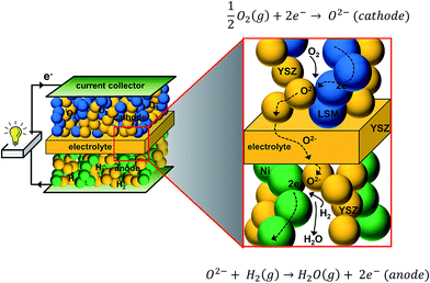 | ||
| Fig. 1 Schematic diagram showing the operating principle of a solid oxide fuel cell (SOFC) (cathode: LSM + YSZ, electrolyte: YSZ, and anode: Ni + YSZ). | ||
To date, the performance of most of the reported SOFCs seems to be limited by the electrodes, thus requiring the search and development of improved anodes and cathodes for low-to-medium temperature SOFCs. The conventional electrode materials are yet to be optimized to perform at the intermediate temperatures (500–700 °C), and alternative new electrodes with higher activity, chemical stability and durability should be developed. The aim of this article is to highlight the currently emerging electrode engineering approaches employed in the cathodes and anodes of SOFCs and its related technologies. Specifically, insights into the infiltration method in cathodes and the ex-solution method in anodes for SOFCs/SOECs are presented. The infiltration method is not only limited to application in cathodes, and the research activities concerning the use of infiltration in anodes are about the same pace as in cathodes.10–12 A part of the review focuses and outlines specific trends and ideas within the topic of infiltration that have been sparking interest in recent years with SOFC cathodes. This article also aims to give an overview of the materials used in state-of-the-art electrodes for SOFCs together with motivation for employing electrode-engineering techniques in the electrodes.
2. Brief overview of SOFC electrode materials
2.1 SOFC cathodes
Despite the high total (electronic and ionic) conductivity of LSM, its poor oxide ion conductivity rather limits the active sites for the oxygen reduction reaction (ORR) to be confined mainly to the triple-phase boundary (TPB) sites. Hence, the electrochemical performance of a cathode fabricated by depositing a layer of LSM onto a dense YSZ electrolyte is mainly dictated by the number of active contact sites of LSM and the YSZ electrolyte. An idea to enlarge the electrochemically active area is to extend the electrolyte through the whole thickness of the LSM layer. Thus, attempts have been made to use a composite of LSM and YSZ, as the cathode in SOFCs (Fig. 1). Several studies have demonstrated that the area specific polarization resistance (ASR) for the ORR of a pure LSM cathode is significantly higher than that of LSM-YSZ composite cathodes.13–16 Apart from the extension of the electrochemically active region, the use of composites can enhance the electrode microstructural stability and also improve mechanical properties due to better adherence to the YSZ electrolyte.17Reduction in the overall electrode polarization resistance for the ORR can be made further by replacing YSZ with an electrolyte material of higher oxide ion conductivity such as Gd-doped ceria (CGO), Sr and Mg-co-doped LaGaO3 (LSGM), and LSM with more electrochemically active mixed ionic and electronic conductors (MIECs). In MIECs, the oxygen exchange could occur at a larger surface of the material due to its appreciable amount of oxygen vacancies ( ) and faster oxide ion transport within the cathode material.
To date, the well-known MIECs, including perovskite-type structure La1−xSrxCo1−yFeyO3−δ (LSCF) and Ba1−xSrxCo1−yFeyO3−δ (BSCF) and layered double perovskite-type LnBaCo2O5+δ are being explored as cathodes for next generation SOFCs.18,19 Several groups have demonstrated that the electrochemical performance of porous LSCF cathodes is superior to that of conventional LSM cathodes.20,21 It should be noted that MIECs generally have high activation energy for oxygen self-diffusion compared to oxide ion electrolytes such as Ce0.9Gd0.1O1.95 (CGO) and LSGM; thus, their ionic conductivity drops sharply with decreasing temperature. For example, the activation energy for oxygen tracer diffusion (EA,D*) in La0.6Sr0.4CoO3−δ is 176 kJ mol−1 while that for CGO is 87 kJ mol−1.22,23 Thus, the addition of high ionic conducting CGO is advantageous for reduced temperature operation. The presence of the solid electrolyte phase in the cathode should serve to enhance the chemical compatibility of the electrode with the electrolyte by improving the adhesion and matching the thermal expansion coefficient (TEC) of the materials. Thus, composite cathodes are generally favored over singe-phase MIECs, even though there is a significant decrease in the electrochemically active surface area of electrodes.
Exploration of other electrolyte and cathode materials may also reduce the energy losses from ohmic resistance and activation polarization resistance. In the case of the ionic conducting component, there are several materials with higher ionic conductivity than YSZ that can be considered,27–34 including fluorite-type Ce0.9Gd0.1O1.95 (CGO), perovskite-type Ba2In2O5, Ba2In1.75Ce0.25O5.125, and La0.9Sr0.1Ga0.9Mg0.1O3 (LSGM),24 and layered structure Bi2VO5.5, Bi2Sr2Nb2GaO11.5, and Bi2V0.9Cu0.1O5.35 (BICUVOX)25 (Fig. 2).32–34 However, some of these other oxide ion electrolyte systems show several disadvantages. For example, LSGM suffers from significant reactivity with perovskite-type structure LSM, LSCF and BSCF electrodes under oxidizing conditions and forms secondary phases in the course of processing.26,27 Bismuth-based oxides are known for their poor thermodynamic stability under reducing atmospheres (e.g., SOFC anode). Doped bi-oxides with MIECs or metals could be used as cathodes in oxidizing atmospheres at intermediate temperatures. Furthermore, doped Bi2O3 has been used with doped ceria as a bi-layer membrane for intermediate temperature SOFCs.28–31 Ceria exhibits relatively easy reducibility at low pO2 leading to the increase in electronic conductivity at elevated temperatures. Therefore, the operating temperature should be kept below 700 °C, if doped ceria is used as the electrolyte to avoid a significant reduction of open circuit voltage (OCV) due to the electronic conduction. However, if these materials are maintained under oxidizing conditions, such as in a SOFC cathode, there appear to be no issues even at higher temperatures. Thus, ceria appears to be the most promising composite material in a SOFC cathode in terms of thermo-mechanical stability and reactivity with common perovskite-type transition metal oxide-based cathodes.
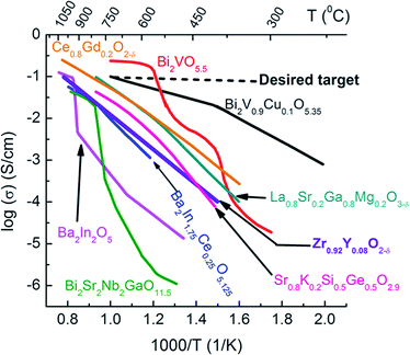 | ||
| Fig. 2 Oxide ion conductivities of some solid electrolytes.32–34 | ||
To ensure the high durability in a SOFC, a careful choice of components for a composite cathode should be made based on chemical and thermo-mechanical compatibility with the electrolyte.35 Cobaltite- and ferrite-based electrodes are not being used as composites due to their poor matching TEC with conventional electrolyte YSZ. A number of studies have demonstrated that highly ionic conducting electrolytes, with MIEC ceramics or metals, can be utilized as cathode materials to improve electrochemical performances. For example, Xia and Liu demonstrated that BICUVOX can be effectively employed in a composite cathode with Ag (57 wt%) as the electronic conducting component.36 This composite cathode showed a remarkable performance of 0.53 Ω cm2 at 500 °C using CGO as an electrolyte. Several optimization studies have been performed for different composite cathodes and found that the optimum amount of solid electrolyte component falls within 30–60 wt%.17 The addition of more electrolytes results in an increase in ORR ASR due to a decrease in the amount of electrocatalysts.
2.2 SOFC anodes
Some of the ideas in the SOFC cathode research have been applied in the case of SOFC anode development. In the case of anodes, Ni has been known to be a good catalyst for the hydrogen oxidation reaction (HOR). However, pure Ni tends to aggregate at high temperatures. The addition of an oxide component such as YSZ not only solves the aggregation problem, as first recognized by Spacil,37 but also improves the electrochemical performance of the anode.10 Indeed, Ni/YSZ anodes are robust, easy to fabricate, and highly efficient for the electrochemical HOR and electrochemical oxidation of syn-gas.38 For the targeted commercial application, however, it is highly desirable that the anode can be fed directly with hydrocarbon fuels such as natural gas. Unfortunately, Ni is also a good catalyst for the decomposition of hydrocarbons to form carbon deposits in the anode surface, which block the gas access in electrochemical reaction zones. Another problem, when using hydrocarbon fuels, is the presence of sulfur as impurity, which exists as gaseous H2S after reforming. Ni-based SOFC anodes have a very low level of tolerance towards sulfur poisoning.10,39 Finding alternatives to Ni/YSZ anodes is the focus of many recent studies that aim at directly utilizing hydrocarbon fuels in SOFCs.The long-term global challenge is to replace the Ni–YSZ cermet anode with alternative H2S and coke stable MIEC ceramics for advanced SOFCs. The presence of ionic conductivity would also serve to enhance the effective size of TPBs. Indeed, in recent studies, the enlargement of the active surface in MIECs was reported in fluorite-type ceria using in situ X-ray photoelectron spectroscopy (XPS).40 A change of the Ce3+/4+ valence state in the electrode upon a bias voltage was a span of 100 μm from the current collector, suggesting that the whole ceria surface could be electrochemically active for the HOR. Chueh et al. also demonstrated that the ‘near-equilibrium’ HOR pathway on ceria-based electrodes is only dominated by electrocatalysis at the MIEC oxide/gas interface, as shown in their electrochemical impedance spectra (EIS) using well-defined pattern electrodes.41 Nonetheless, the effective surface area of other MIEC anodes is yet to be deeply investigated. Over the last two decades, a large number of promising MIECs, including Ce1−xMxO2−δ (M = Ni, Cu), La1−xSrxCr1−yMnyO3, and BaZr0.1Ce0.7Y0.2−xYbxO3−δ, have been shown to have excellent electrochemical performance under impure fuel conditions.42,43 The design strategies of next generation SOFC anodes were recently reported.3,7,8,44
3. Emerging SOFC electrode engineering techniques
Not only the electrode material chemical composition, but also the electrode engineering is equally important to optimize the transport of electrons, gases, and ions in the electrode layer. Electrode engineering parameters include the processing parameters such as temperature, sintering duration and atmosphere, which determine the final microstructure and chemical composition of the electrode. The choice of techniques commonly depends on the cell design, which can be tubular, planar, and more recently, “micro-fabricated”.45–49The common way to prepare cathodes in a planar design, particularly in an anode supported SOFC, is to deposit the cathode after preparing the anode/electrolyte assembly, using slurry coating, screen printing, tape casting, and wet powder spraying methods.50 In these methods, the thickness of the deposited layer after sintering is usually several micrometers. The sintering temperature is a compromise between the formation of sufficient connection between the electrode and the electrolyte and the prevention of solid-state reactions between the components of the cathode and the electrolyte. Sometimes, the sintering temperature range is very narrow such that the choice of materials for a two-phase combination is very limited. For example, it may be thought that a material can replace LSM in the LSM–YSZ composite with a superior electrocatalytically active Sr-doped LaCoO3 (LSC) cathode. However, at temperatures above 1000 °C, it is known that LSC reacts with YSZ.51,52 A firing temperature lower than 1000 °C may be attempted to fabricate a LSC–YSZ composite cathode, but the resulting cathode would not be optimal as YSZ requires about 1000 °C to attain sufficient connection of grains.53
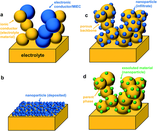
The surface areas of cathodes prepared by conventional methods are normally low; hence they exhibit a high ASR at low operating temperatures. This drawback has initiated great interest in nano-scaled electrodes, which possess an inherently large electrochemically active surface area. Generally, there are three ways to prepare nano-sized particle electrodes for SOFCs namely, thin-film deposition, infiltration, and ex-solution (Fig. 3).54
3.1 Thin-film deposition
In the conventional thin-film deposition method, the cathode is deposited on a dense solid oxide ion electrolyte substrate (Fig. 3b). The thicknesses of electrodes attained in this method range typically from the submicron to several micrometer level, and they are sometimes called as “micro (μ)-SOFCs”.55 Most relevant thin-film deposition techniques for SOFC/SOEC applications include vacuum deposition (for e.g., physical vapor deposition (PVD), chemical vapor deposition (CVD), and pulsed laser deposition (PLD)) as well as liquid precursor-based thin-film deposition (for e.g., spray deposition, electrophoretic deposition (EPD) and spin- and dip-coating) methods. An excellent review of some of these techniques was written by Beckel et al. in 2007.56 Typical cathode materials used in μ-SOFCs include Pt, LSC, LSCF, and BSCF.56In the work of Dieterle et al., a dip coating technique was employed to obtain nano-porous La0.6Sr0.4CoO3−δ thin films with the thickness in the range of 150–200 nm.57 ORR ASR (Rp) of 0.023 Ω cm2 at 600 °C was reported.57 However, a significant degradation of performance (ASR increased to 0.069 Ω cm2 at 600 °C) was observed after 100 h. Employing the spray pyrolysis technique, Darbandi et al. obtained an ORR ASR (Rp) of 0.038 Ω cm2 at 600 °C for nano-porous La0.25Ba0.25Sr0.5Co0.2Fe0.8O3−δ thin films (≤1 μm),58 but with no detail discussed on the stability. The use of the thin-film deposition method is promising but there are several issues such as optimization of the electrode microstructure, substrate choice and component durability that need to be addressed before commercialization.59 A summary of electrochemical performances of selected SOFC electrodes prepared using various preparation techniques is shown in Table 1.13,18,54–56,60–66
| Technique | Configuration | Electrolyte | Electrodes (thickness) | Performance | Remarks | Reference |
|---|---|---|---|---|---|---|
| Conventional (spin coating, spraying) | Symmetrical cell | YSZ | La0.8Sr0.2MnO3 (∼20 μm) | R p: 51.03 Ω cm2 at 600 °C | n/a | 13 |
| Symmetrical cell | YSZ | La0.8Sr0.2MnO3/YSZ 50 wt% (∼20 μm) | R p: 11.37 Ω cm2 at 600 °C | n/a | 13 | |
| Symmetrical cell | YSZ with CGO interlayer | La0.6Sr0.4CoO3−δ (∼20 μm) | R p: 1.8 Ω cm2 at 600 °C | n/a | 60 | |
| Symmetrical cell | CGO | La0.6Sr0.4CoO3−δ/CGO 30 wt% (∼20 μm) | R p: 0.7 Ω cm2 at 600 °C | n/a | 60 | |
| Full cell | YSZ with CGO interlayer on cathode side | Cathode: La0.6Sr0.4CoO3−δ/CGO 30 wt% (∼20 μm) anode: Ni/YSZ | P max: 0.27 W cm−2 at 600 °C | 300 h, 650 °C at 0.625 A cm−2, H2/air: cell voltage drop from 483 to 474 mV during the first 20 h, stable afterwards | 18 | |
| Symmetrical cell | CGO | (La0.6Sr0.4)1−xCo0.2Fe0.8O3−δ/CGO 50 wt% (∼20 μm) | R p: 0.19 Ω cm2 at 600 °C | n/a | 61 | |
| Symmetrical cell | YSZ | (La0.6Sr0.4)1−xCo0.2Fe0.8O3−δ/CGO 30 wt% (∼20 μm) | R p: 1 Ω cm2 at 600 °C | 200 h, 800 °C: Rp increase from 0.025 to 0.1 Ω cm2 with no change in serial resistance, Rs | 61 | |
| Symmetrical cell/Three electrode | Ce0.85Sm0.15O2−δ | Ba0.5Sr0.5Co0.8Fe0.2O3−δ (∼20 μm) | R p: 0.055–0.071 Ω cm2 at 600 °C | n/a | 60 | |
| Thin film-spin coating | Symmetrical cell | YSZ with CGO interlayer | La0.25Ba0.25Sr0.5Co0.2Fe0.8O3−δ (≤1 μm) | R p: 0.038 Ω cm2 at 600 °C | n/a | 58 |
| Symmetrical cell | CGO | La0.6Sr0.4CoO3−δ (∼0.15–0.2 μm) | R p: 0.023 Ω cm2 at 600 °C | 100 h, 700 °C: Rp increase from <0.03 to 0.069 Ω cm2 | 57 | |
| 100 h, 800 °C: Rp increase from <0.03 to 0.16 Ω cm2 | ||||||
| Thin film-metal–organic deposition | Symmetrical cell | YSZ | La0.6Sr0.4CoO3−δ (∼0.2–0.3 μm) | R p: 0.146 Ω cm2 at 600 °C | 100 h, 600 °C: Rp increase is ∼3.67x or 0.146 to ∼0.54 Ω cm2 | 62 |
| YSZ with CGO interlayers | La0.6Sr0.4CoO3−δ (∼0.2–0.3 μm) | R p: 0.130 Ω cm2 at 600 °C | 100 h, 650 °C: Rp increased to ∼0.14 Ω cm2 | 62 | ||
| Infiltration | Symmetrical cell | YSZ | Backbone: La0.75Sr0.25Mn1.05O3−δ/YSZ (thickness not reported) | R p: 0.39 Ω cm2 at 600 °C | n/a | 63 |
| Infiltrate: dual La0.75Sr0.25Mn1.05O3−δ/Ce0.8Sm0.2O1.9 | ||||||
| Symmetrical cell | Ce0.8Sm0.2O1.9 | Backbone: Ce0.8Sm0.2O1.9 (∼50 μm) | R p: 0.29–0.31 Ω cm2 at 600 °C | 20 cycles of 800 to 500 °C then measure at 600 °C, continue 10 cycles of 800 °C to RT, hold at 600 °C for 3 months: From 0.306 to 0.29 Ω cm2 | 64 | |
| Infiltrate: La0.6Sr0.4CoO3−δ | ||||||
| Symmetrical cell | CGO | Backbone: CGO (∼25 μm) | R p: 0.24 Ω cm2 at 600 °C | ∼336 h at 650 °C: 0.17–0.23 Ω cm2 to final ∼0.14 Ω cm2 | 65 | |
| Infiltrate: La0.6Sr0.4Co0.2Fe0.8O3−δ | ||||||
| Symmetrical cell | CGO | Backbone: CGO (∼25 μm) | R p: 0.044 Ω cm2 at 600 °C | ∼450 h at 600 °C: 0.044 Ω cm2 to final ∼0.07 Ω cm2 | 54 | |
| Infiltrate: La0.6Sr0.4CoO3−δ | ||||||
| Ex-solution | Full cell | YSZ | Cathode: LSM/YSZ 50 wt% | R p (anode): 0.5 Ω cm2 at 600 °C | n/a | 66 |
| Anode: La0.3Sr0.6Ce0.1Ni0.1Ti0.9O3 (thickness not reported) | P max: 0.26 W cm−2 at 800 °C (5000 ppm H2S/H2) | |||||
| Full cell | YSZ | Cathode: LSM/YSZ 50 wt% | R p (anode): 1.2 Ω cm2 at 600 °C | n/a | 66 | |
| Anode: La0.3Sr0.6Ni0.1Ti0.9O3 (thickness not reported) | P max: 0.175 W cm−2 at 800 °C (5000 ppm H2S/H2) | |||||
| Full cell | YSZ | Cathode: LSM/YSZ 50 wt% | R p (anode): 0.25 Ω cm2 at 600 °C | n/a | 66 | |
| Anode: La0.7Sr0.3Cr0.85Ni0.15O3 (thickness not reported) | P max: 0.470 W cm−2 at 800 °C (5000 ppm H2S/H2) | |||||
| Full cell | YSZ | Cathode: LSM/YSZ 50 wt% | R p (anode): 0.2 Ω cm2 at 600 °C | n/a | 66 | |
| Anode: La0.7Sr0.3Cr0.85Ni0.11Fe0.04O3 (thickness not reported) | P max: 0.560 W cm−2 at 800 °C (5000 ppm H2S/H2) | |||||
| Full cell | YSZ | Cathode: LSM/YSZ 50 wt% | R p (anode): 0.35 Ω cm2 at 600 °C | n/a | 66 | |
| Anode: La0.7Sr0.3Cr0.85Fe0.15O3 (thickness not reported) | P max: 0.350 W cm−2 at 800 °C (5000 ppm H2S/H2) |
3.2 Infiltration technique
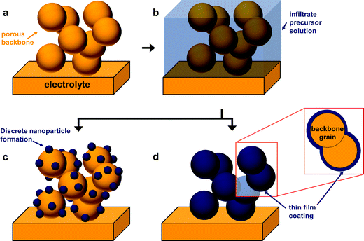
The fabrication of SOFC components via infiltration has been widely employed in recent years and several excellent reviews have already been published.10–12,38,53,67,68 The present article aims to highlight nano-/microstructuring strategies that are related to infiltration and show opportunities with this technique. In general, in an infiltration technique, a liquid solution usually composed of dissolved metal nitrates is introduced into a pre-formed porous backbone, followed by drying and calcination to produce the desired oxide phase (Fig. 3c). The infiltrated material can form either discrete nanoparticles or a thin continuous network on the surface of the electrolyte backbone.12 Capillary forces enable the incorporation of the infiltrate into the porous backbone, through vacuum assisted infiltration.54,69A schematic of the infiltration procedure is shown in Fig. 4. Here, the backbone can be inherently functional or skeletal as classified in the recent review by Ding et al.67 Inherently, functional backbones would include a single-phase MIEC or a composite of an electrolyte and an electronic conductor. Skeletal backbones are ionic conducting scaffolds such as YSZ, CGO and LSGM. Depending on the combination of the infiltrate and the backbone material, infiltration into the as-sintered backbones is performed to increase catalytic activity and ion and electron conductivity.12
Compared to the conventional composite method, the major advantage of the infiltration technique is that nanoparticles of the catalyst can be established resulting in highly enlarged zones of electrocatalytic materials. By employing a skeletal backbone of ionic conducting scaffolds, the electrode process offers a lower ASR. The bulk oxygen ion conductivity of the ionic conducting backbone is much higher than that of the MIEC, which allows the electrochemically active thickness of the electrode to be spread out further in the electrode, and thus, significantly increases the catalytically active surface area. In addition, infiltration can be independent of other sintering steps, and such a process can be integrated on electrodes prepared by conventional methods including screen-printing, tape casting and spraying. The possible chemical reactions between the infiltrated and backbone phases are also minimized because of the low calcination temperature involved. This could also mean that a wider variety of catalyst materials can be employed which cannot be otherwise used in the conventional composite electrodes. Specific trends in infiltration are discussed more thoroughly in the succeeding section.
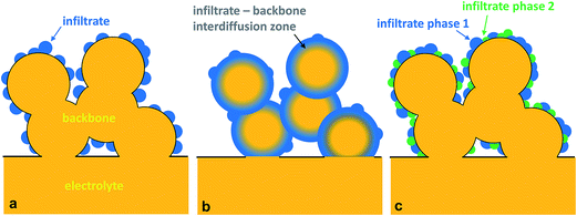
The infiltration method has shown improved electrochemical performance for a variety of candidate materials. Especially for SOFC cathodes, several combinations including perovskite/YSZ and perovskite/ceria, especially lanthanum cobaltite-based perovskite/ceria combinations, have been studied.10,38,67 To date, three approaches, namely morphological control, core shell structure formation, and multi-component/multiphase infiltrates, have been used to obtain functional nanostructured electrodes with high electrochemical activity for SOFCs. A schematic of these three approaches is shown in Fig. 5.
The physical properties and composition of the infiltrate solution can greatly affect the morphology of the catalyst or the infiltrate. Fig. 6 shows an example of the varying microstructures depending on the nature of the infiltrate precursor solution. Thus, engineering or finding the right combination of the components of the infiltrate precursor solution is very important for SOFC electrodes. Usually, the infiltration precursor solution consists of a solvent, surfactant, and metal nitrates. The purpose of the surfactant is to not only form complexes with metal cations to assist the formation of a crystalline phase but also to control the particle size through suitable micelles.78,79 Typical examples of surfactants used in SOFCs are citric acid,67,78,80 Triton X-series,78,79,81 and co-polymers.77,82 In addition to the surfactant, chelating agents/dispersants are added to the infiltrate. They effectively separate the cations, thereby improving mixing of the cations in the infiltrate precursor solution. Problems such as inhomogeneous dispersion of catalyst crystals into the porous host and impurity phase formation, when the infiltrate solution consists of more than 3 elements, can be mitigated by the addition of dispersants to the infiltrate.
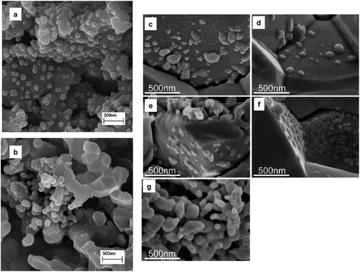 | ||
Fig. 6 Examples of the infiltrate showing different microstructures based on infiltration solutions (a) 1.44 M Sm0.5Sr0.5CoO3 (SSC) nitrate solution with water![[thin space (1/6-em)]](https://www.rsc.org/images/entities/char_2009.gif) : :![[thin space (1/6-em)]](https://www.rsc.org/images/entities/char_2009.gif) ethanol volume ratio (1 ethanol volume ratio (1![[thin space (1/6-em)]](https://www.rsc.org/images/entities/char_2009.gif) : :![[thin space (1/6-em)]](https://www.rsc.org/images/entities/char_2009.gif) 0.6),78 (b) 1.44 M SSC nitrate solution (without ethanol);78 (c) pure nitrate derived 0.5 M SSC (electrode/electrolyte interface),81 (d) triton X–derived 0.5 M SSC (electrode/electrolyte interface),81 (e) citric acid derived 0.5 M SSC (electrode/electrolyte interface),81 (f) triton X–derived 0.293 M SSC (electrode/electrolyte interface), and (g) citric acid derived 0.5 M SSC (within electrode).81 Reprinted with permission. 0.6),78 (b) 1.44 M SSC nitrate solution (without ethanol);78 (c) pure nitrate derived 0.5 M SSC (electrode/electrolyte interface),81 (d) triton X–derived 0.5 M SSC (electrode/electrolyte interface),81 (e) citric acid derived 0.5 M SSC (electrode/electrolyte interface),81 (f) triton X–derived 0.293 M SSC (electrode/electrolyte interface), and (g) citric acid derived 0.5 M SSC (within electrode).81 Reprinted with permission. | ||
The viscosity of the infiltrate solution is subject to change by all of the constituents of the infiltrate precursor solution. Van Dillen et al. have found non-uniform distribution of derived catalysts when the infiltrate has a high viscosity.83 Jiang et al. have shown a more uniform catalyst layer when low viscosity infiltrate precursor solution was used.84 A disadvantage of low viscosity is that a large number of infiltration cycles are needed to introduce a sufficient amount of catalysts. Increased surfactant and/or metal cation concentration effectively increases the viscosity. An advantage of increased metal cation concentration is that the number of infiltration cycles could be reduced. Sholklapper et al. attempted a single-step infiltration using a concentrated LSM nitrate precursor solution with a commercial polymeric surfactant (Triton-X100) and shown that it is possible to form a thin layer of a continuous network of nano-structured LSM on an YSZ backbone.79 A problem though with highly viscous and concentrated infiltrate solution is penetration in the porous structure.10 Researchers are continually tackling the task of improving the infiltrate solution to obtain uniformly distributed and phase pure catalysts which is not time consuming and does not hinder its practical application in SOFCs.
The other scheme to influence the morphology of the catalyst layer using the infiltration technique is to engineer the backbone. A typical backbone for infiltration is designed to have a very high porosity to provide easy penetration of the infiltration solution and transport of gas species once it is utilized as an electrode. One of the best examples of backbone microstructure engineering is from the study of Küngas et al. where an YSZ backbone is etched with hydrofluoric acid to maximize the TPBs.85Fig. 7 shows a comparison of the resulting microstructures from HF etching of the YSZ backbone to control the morphology of the infiltrated electrode.85 Many studies were reported to understand the effect of morphology on electrochemical performance but a simple enlargement of the surface area for the oxygen surface exchange reaction could not explain the enhancement.54,57,86,87
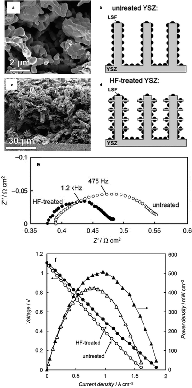 | ||
| Fig. 7 Example of backbone engineering from Küngas et al.85 (a) YSZ backbone before HF etching, (b) schematic of untreated YSZ, (c) YSZ after HF etching, (d) schematic of the HF etched-YSZ backbone, (e) impedance comparison of full cells with untreated and HF-treated backbone (LSF infiltration) cathode and Pd–CeO2 anode in humidified (3% H2O) H2 and (f) the corresponding I–V and power dens\lity curves of the fuel cell. Reprinted with permission. | ||
Inter-diffusion of the elemental components of the infiltrate and backbone material to form new compound(s) or a gradient of inter-diffused elements at the interface could be beneficial, if a material with superior electrical/electrochemical properties and an electrode with highly improved electrochemical activity with increased morphological stability can be obtained. Increased morphological stability may be inferred from the resulting new microstructure, as shown schematically in Fig. 7b. Essentially, a thin-film running through the entire grain of the backbone can form a continuous network of the necessary catalyst for ORR and HRR. The problem of possible discontinuity among the infiltrate through grain-growth and particle segregation at elevated temperatures could be avoided using this method. Several studies have exploited this idea of forming highly active surfaces due to the migration of species in the infiltrate or the backbone material. An example of this kind of electrode is the diffusion of Mn from LSM electrodes to YSZ surfaces.92,93
The idea of a core–shell structure to take advantage of the desirable physical properties of the reacted entities between the backbone and infiltrate is shown recently by Chen et al.94 Here, a core–shell electrode composed of a Sm0.2Ce0.8O1.9 (SDC) scaffold electrolyte, and a MIEC, Sm, Ce-doped SrCoO3−δ, was formed from solution infiltration in combination with high temperature reactive sintering (Fig. 8a).94 The concept of the core–shell structure between SrCoO3−δ (SC) and SDC was utilized to develop a high performance SOFC cathode.95 SC is unstable and is a moderate electrocatalyst for the ORR. A and/or B-site doping in SC is usually performed to stabilize the perovskite phase structure and increase its ionic and/or electronic conductivity.94,96,97 In the study by Zhou et al.,95 SC and SDC powders were mixed and fired at varying temperatures. XRD confirmed the chemical reaction between the SC and SDC; specifically, the formation of a cubic lattice structure in the reacted powder was attributed to the incorporation of Ce into the B-site of perovskite-type SC. The evidence of the formation of a high electronic conductivity phase was inferred from the fact that the electronic conductivities of the SC + SDC composite sintered at 1000 °C have reached ca. 100–200 S cm−1 at 300–900 °C in air, while that of pristine SC showed 5–25 S cm−1. The reaction between SC and SDC was also found to have improved ionic conductivity compared to the negligible ionic conductivity of the SC.
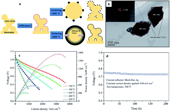 | ||
| Fig. 8 (a) Schematic of the preparation for the core–shell formation derived from infiltration and reactive sintering from the work of Chen et al.;94 (b) TEM of the core-shell structure (c) I–V and power density curves of cells with the Ni–YSZ anode, YSZ electrolyte, and SC infiltrated SDC cathode sintered at 1000 °C with operating temperatures from 550 to 750 °C. (d) The long-term behavior of the fuel cells. Reprinted with permission. | ||
Chen et al.94 performed infiltration of SC onto SDC scaffolds followed by reactive sintering (>900 °C for 2 h). TEM results, as shown in Fig. 8b, confirm a core–shell structure with the core part seen as a darker area and the shell part seen as a brighter area with a thickness less than 100 nm. The electrochemical performance of an anode supported SOFC with the core–shell structured cathode exhibited much better electrochemical performance compared to SOFCs with a single-phase mixed conducting electrode or normal composite electrode (Fig. 8c).94 It was also shown that such an electrode is very stable (Fig. 8d). Formation of core–shell structures offers great promise in obtaining electrodes with improved electrochemical performance and enhanced thermal stability. With the ease of fabrication and firing using the infiltration method, it would be no surprise to find that several research studies using the idea of a core–shell structure using various combinations of materials would emerge in the immediate future.
In the case of cathodes for SOFCs, perhaps the first known motivation in pursuing multi-phase materials is from the identification of Sase et al.,103 that the hetero-interfaces in the composite of La0.6Sr0.4CoO3 (LSC-113) and (La,Sr)2CoO4 (LSC-214) showed about three orders of magnitude higher oxygen surface exchange coefficient than that of single-phase LSC-113. Several studies have followed attempting to further explain the origins of such enhancement.104–106 Employing first-principles calculation, Han and Yildiz proposed that both the anisotropic oxygen incorporation kinetics of the LSC-214 and the lattice strain in the vicinity of the interface are important contributors to oxygen-exchange reaction enhancement in the LSC-113/LSC-214 system.105 The work of Hayd et al. on LSC-113 thin-film cathodes, derived by metal organic deposition and with a nanoscaled microstructure, has shown that the presence of secondary phases such as LSC-214 and Co3O4 leads to significant improvement in oxygen surface–exchange properties (47 times better surface exchange coefficient than that of the bulk LSC-113).107
Mutoro et al.,102 investigated the effect of adding particles of simple oxides on the surface of La0.8Sr0.2CoO3−δ on the oxygen reduction activity. They have found that a small amount of secondary phase (La, Co, and Sr-(hydr)oxides/carbonates) on La0.8Sr0.2CoO3−δ can significantly affect the electrode performances. Interestingly, Sr-decoration on top of the La0.8Sr0.2CoO3−δ surface leads to an enhanced oxygen surface exchange coefficient, while La- and Co-decoration led to no change and reduction of the oxygen surface exchange coefficient, respectively. The enhancement in the case of Sr-decorated surfaces was attributed to the catalytically active interface regions between surface of Sr-enriched particles and the La0.8Sr0.2CoO3−δ surface. The topic of interphase enhancement by the presence of secondary phases is an exciting area. Advancements in the nanoparticle synthesis may guide researchers on how to control the formation of such multi-phase infiltrates in actual SOFC or SOEC electrodes.
3.3 Ex-solution method
In the ex-solution method, catalytically active transition metals, which were first substituted in a host oxide lattice under oxidizing conditions, are released to the surface of the host oxide under reducing conditions (Fig. 3d). The incorporation of precious dopants (e.g., Ru, Pt, and Rh) into the perovskites as the catalyst was reported in the 1970s.70 For example, La0.6Sr0.4Co0.94Pt0.03Ru0.03O3 was tested to remove simultaneously HC, CO and NO from vehicle exhausts. Electron spectroscopy for chemical analysis showed a change in the valence state of the precious dopants in a reducing atmosphere.70 In 2002, Nishihata et al. demonstrated a novel catalyst of nano-sized Pd, which was generated in situ from perovskite-type LaFe0.57Co0.38Pd0.05O3 (Fig. 9).71 Such a catalyst was used to oxidize CO and unburned hydrocarbons in automotive emissions. The catalyst can retain its high activity for a long period, with minimal aggregation due to special structural architecture, where nano-particles are partially confined into the host compound. Such a concept was later further optimized to incorporate Rh, Pt and Pd into the catalytic converters by Daihatsu, and it is commonly called as “Super Intelligent Catalyst”.71–73 | ||
| Fig. 9 The duration of ageing in engine exhausts of the perovskite-type LaFe0.57Co0.38Pd0.05O3 and conventional Pd–Al2O3 composite for the conversion of CO and NOx.71 TEM images of Pt grains of catalysts aged in engine exhausts at 900 °C for 100 h from CaTi0.95Pt0.05O3 and Pt/γ-Al2O3 are shown for comparison.73 Reprinted with permission. | ||
Neagu and others further modified an ex-solution concept by selecting SrTiO3-type MIEC as the host compound, and replacing the precious metals with Ni for the HOR catalyst.74 For the first time, the new-type catalyst was demonstrated as a robust electrochemical catalyst for SOFCs and SOECs.68 The targeted dopants are first doped into the MIEC backbone in air, as they have high solubility to form a single-phase perovskite-type structure. As the MIEC is exposed at elevated temperatures under low pO2, some dopants can be ex-soluted due to the change of the chemical solubility and formation of new chemical formulism of MIECs. The negative Gibbs free energy of the formation of net reaction drives this spontaneous chemical reduction reaction from their binary metal oxide systems at elevated temperatures under a reducing atmosphere. The Gibbs free energy of some common metal oxides as a function of temperature is shown in Fig. 10.75 This diagram is generally used by metallurgists to find suitable temperature and pO2 for the reduction of the ores of important metals. For a given reaction, the position of a line in the diagram shows the chemical/thermodynamic stability window of the metal oxides.
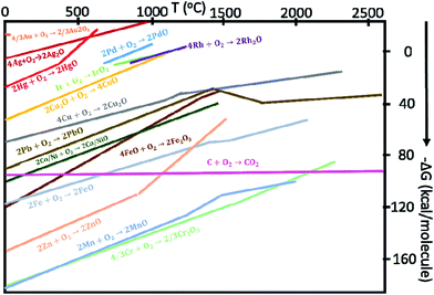 | ||
| Fig. 10 The Gibbs free energy for some metal or metal oxide oxidation reactions as a function of temperature.75 | ||
• For a stoichiometric perovskite ABO3, the ex-solution process can yield a B-site deficient perovskite AB1−xO3−δ and nanoparticles of B-site ions, i.e., ABO3(s) → AB1−xO3−δ′(s) + xB(s).
• For an A-site deficient perovskite A1−xBO3−δ, the ex-solution process can yield a stoichiometric perovskite ABO3−δ and nanoparticles of B-site ions, i.e., A1−xBO3−δ(s) → (1 − x)ABO3−δ′(s) + xB(s).
• For a stoichiometric perovskite ABO3, the ex-solution process can also yield A and B-site defective perovskites A1−xB1−yO3−δ, nanoparticles of A-site and B-site ions, i.e., ABO3(s) → A1−xB1−yO3−δ′(s) + xA(s) + yB(s).
Early studies by Ruiz-Morales et al. suggested that defects could also be detrimental to the transport properties if their concentration exceeds a certain threshold, and defects tend to order in the structures as intergrowth structures, as shown in La4Srn−4TinO3n+2 (Fig. 11).109 By increasing the value of n toward 12, the intergrowth layer diminished, and the oxide-ion conductivity reached its highest value. To characterize the microstructure of samples, Neagu et al. examined stoichiometric La0.3Sr0.7Ti0.94M0.06O3−δ (M = Ti, Ni), but they did not observe nanoparticle growth on the substrate.74 This result was not surprising since DFT calculations showed rather small negative Gibbs free energies for those transition metals. Furthermore, they investigated A-site deficient compounds, La0.4Sr0.4Ti0.94M0.06O3−δ (M = Mn, Fe, Ni, and Cu) and ex-solution of nanoparticles was observed in high resolution scanning electron microscopy images (Fig. 12).74 This result showed that off-stoichiometry could be a means to control the amount and size of nanoparticles ex-soluted on the host oxides. Neagu et al. pointed out that the case 2 is more feasible to ex-solute metallic nanoparticles as the process involves “unstable” to “stable” conversion.
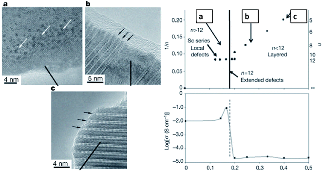 | ||
| Fig. 11 The intergrowth of oxide-ion defects in the perovskite and their impact on the oxide-ion conductivity of La4Srn−4TinO3n+2.109 Reprinted with permission. | ||
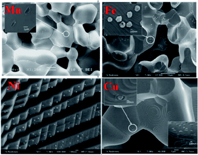 | ||
| Fig. 12 Scanning electron microscopy (SEM) images of the ex-soluted nanoparticles from La0.4Sr0.4Ti0.94M0.06O3−δ (M = Mn, Fe, Ni and Cu).74 Reprinted with permission. | ||
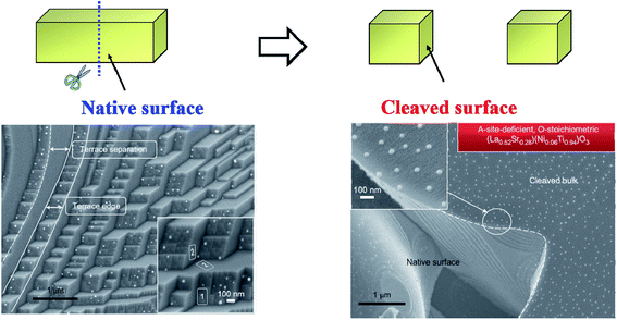 | ||
| Fig. 13 Schematic diagram of the surface-dependent ex-solution for La0.52Sr0.28Ni0.06Ti0.94O3.110 Reprinted with permission. | ||
In addition to the A-site deficient (La1−xSrx)1−yTiO3-type perovskites, ex-solution was also found in other structure-type hosts including fluorite-type CeO2, and rutile-type NbTiO4 (Fig. 14).111–115 Xiao and Qin found that Sr0.95Ti0.76Nb0.19Ni0.05O3 and La0.18Sr0.72Ti0.9Fe0.1O3 perovksites could ex-solute nanoparticles of Ni and Fe, respectively.111,112 Papargyriou and Yoon observed the ex-solution of Ni and Ru nanoparticles from La1−xSrxCr1−yMyO3 (M = Mn, Fe) and La0.4Sr0.6Ti1−xRuxO3 (0 < x < 0.05), respectively.113,114 Thalinger et al. found, for the first time, that nanoparticles of SrO and Fe could be ex-soluted from the A and B-site stoichiometric perovskite-type La0.6Sr0.4FeO3.115 These results have an important implication that BaO could be ex-soluted from the perovskite-type structure which showed anti-coking properties by facilitating the H2O vapor to oxidize deposited carbon.116
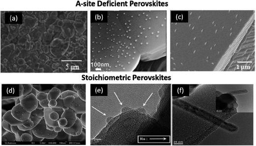 | ||
| Fig. 14 Typical example of A-site deficient and stoichiometric perovskites that ex-solute nanoparticles in reducing atmospheres at elevated temperatures.111–115 (a) La0.18Sr0.72Ti0.9Fe0.1O3,112 (b) Sr0.95Ti0.76Nb0.19Ni0.05O3,111 (c) La0.4Sr0.4Ti0.94Ni0.06O3,112 (d) La0.75Sr0.25Cr0.475Fe0.475Ni0.05O3,113 (e) La0.4Sr0.6Ti1−xRuxO3,114 and (f) La0.6Sr0.4FeO3.115 Reprinted with permission. | ||
For the first time, Qi and Wei reported metal/metal alloy ex-solution in a non-perovskite-type structure. For example, Ni and Ni1−xCux were stabilized from Ce0.9Ni0.1O2 and NbTi0.5Ni0.25Cu0.25O4, respectively (Fig. 15).117,118 The latter alloy is of great interest as the catalytic activity and chemical stability could be tailored as a function of Cu content. Nonetheless, the strategic design poses some difficulties in the control of well-defined alloys and their microstructures. Using TGA, Sun et al. showed that the onset temperatures for the reduction reaction of Ni and Fe are slightly different (Fig. 16).66 As a result, a core–shell structure for some of the ex-soluted species could be observed with a Fe-rich core and Ni-rich shell. Nonetheless, it is very challenging to understand the reduction behavior of individual species (e.g., Ni and Fe) from TGA and PXRD. These observations provided the valuable information about the total reduction of Ni and Fe. Stoichiometry and defects could alter the lattice energy of metal oxide systems, and affect both the kinetics and the thermodynamics of the ex-solution processes.119–121
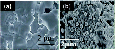 | ||
| Fig. 15 Scanning electron microscopy (SEM) images of Ni and Ni1−xCux nanoparticles ex-soluted from Ce0.9Ni0.1O2 (a) and NbTi0.5Ni0.25Cu0.25O4 (b), respectively.117,118 Reprinted with permission. | ||
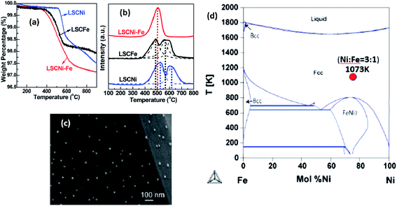 | ||
| Fig. 16 (a) Thermogravimetric analysis (TGA), (b) temperature programmed reduction (TPR) and (c) scanning electron microscopy (SEM) of the Fe1−xNix alloy ex-soluted from La0.7Sr0.3Cr0.85M0.15O3−δ (M = Fe1−xNix). (d) Phase diagram of the Fe1−xNix alloy.66 Reprinted with permission. | ||
Besides SEM images, Neagu et al. studied the microstructure of the substrate after treatment with acid to dissolve the Ni nanoparticles grown on its surface.110 Atomic-force microscopy (AFM) images revealed that the part of the ex-soluted nanoparticles were embedded in the substrate at about 100 nm deep (Fig. 17).110 Such nano-socked Ni particles were later found to have better thermal and chemical stability over sintering and coking, respectively. They hypothesized that the diffusion of Ni particles could be hard since they have to overcome the large barrier of the socket where they are located. Moreover, the carbon nanotubes are highly limited to grow to certain directions, and therefore, the Ni-locked surface seems to have less coking compared to bare Ni surfaces.
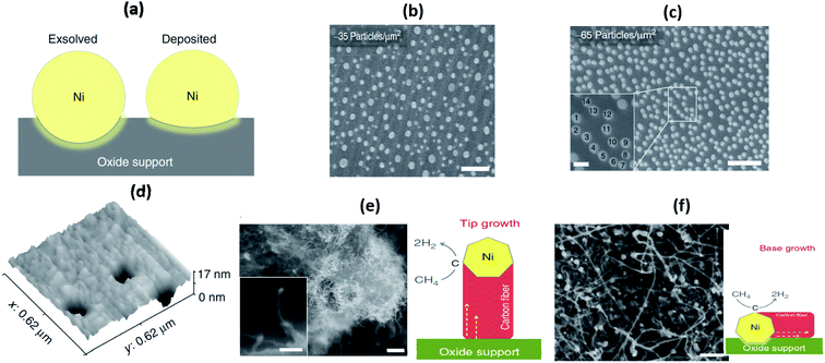 | ||
| Fig. 17 (a) Schematic illustration of the particle–substrate interface for deposited and ex-soluted Ni particles on the oxide backbone, (b) and (c) SEM micrographs of vapour-deposited Ni particles on the perovskite-type La0.4Sr0.4TiO3 surface, (d) three-dimensional AFM images showing sockets of Ni after etching in HNO3, and (e) and (f) SEM micrographs of Ni-deposited La0.4Sr0.4TiO3 samples after the coking test and schematic of possible carbon fiber growth mechanisms.110 Reprinted with permission. | ||
Very recently, Oh et al. further studied the formation mechanism of these ex-soluted nanoparticles by using AFM on surfaces to understand different exposure times in reducing atmospheres (Fig. 18).122 They observed that some pits were formed prior to the emergence of nanoparticles. They hypothesized that a movement of ions should occur near the surface to form pits at 600 °C in dry H2. At 700 °C, Ni nanoparticles were found to grow confined inside the pits. Such an observation might indicate that the species involved in the ionic diffusion in the first stage are likely different from the species that emerged in the second stage.
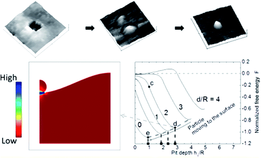 | ||
| Fig. 18 Top panel shows the AFM images of pit in the perovskite-type La0.4Sr0.4Ti0.97Ni0.03O3−δ after reduction at 600 °C under dry H2 and 700 °C under dry H2, and the bottom panel shows the calculated normalized free energy versus pit depth.122 Reprinted with permission. | ||
Previous studies have shown that bond valence sum (BVS) has been used to predict the ionic pathways in solids.35,123–127 Kan et al. recently explored the use of a BVS map to predict the diffusion behavior of ions in the perovskite-type structure at elevated temperatures.124 The ex-solution mechanism is yet to be understood deeply; however, it is likely involved in the diffusion of cations to the surface before the cations are being reduced. BVS calculations could be useful to understand bond valence of metals before and after ex-solution and to understand structural stability. The low BVS mismatch pathways may suggest the facile diffusion pathways for particular ions. Calculation was conducted on various Ni-doped perovskite-type SrTiO3 compounds to understand the potential ex-solution of A and/or B-site ions. The results revealed an interesting phenomenon that Sr2+ ions in the A-site (with smaller BVS mismatches) are more ready to diffuse than the Ni2+ ions in the B-site (Fig. 19), suggesting that the formation of the metal might be initiated by the migration of A-site ions.
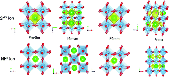 | ||
| Fig. 19 Bond valance sum (BVS) map calculation revealed the Sr2+ and Ni2+ ions conduction pathway in the perovskite-type SrTiO3 compound. 3D BVSMAPPER was used to calculate the BVS map.127 The yellow contour surface with a low BVS mismatch of 10 and 2 for Sr2+ and Ni2+ ions in SrTi0.95Ni0.5O3 with different space groups. The imported crystallographic information files (cif) were obtained from the International Centre for Diffraction Data (ICDD) database (J. Phys. Soc. Jpn., 1965, 20, 179; J. Phys. Soc. Jpn., 1978, 45, 206; Mater. Res. Bull., 1973, 8. 545; Philos. Mag., 2006, 86, 2283). | ||
Conventional Ni-based SOFC anodes are known to suffer coking and poisoning when hydrocarbons with ppm H2S are used as fuels. On the other hand, many MIECs are shown to have higher chemical stability toward those fuels, but less electrochemically active resulting in lower power outputs. Among the reported MIECs, La1−xSrxTiO3 (LST) is known to be highly stable in hydrocarbons and H2S, but it also has a drawback of low electrochemical activity. Sun et al. tried to improve the electrochemical activity of LST-type perovskites by decorating their surface with nano-sized Ni and Ce through an ex-solution method.128 A series of Ni and Ce-doped La0.3Sr0.6Ce0.1Ni0.1Ti0.9O3 perovskites were prepared and their HOR activity was investigated (Table 1).66 On the basis of their I–V curves, the Ni and Ce co-doped samples (LSCNT) reached an impressive peak power density of 650 mW cm−2 in 5000 ppm H2S/H2 at 900 °C, and it may be related to the small polarization resistance of 0.2 Ω cm2. Similarly, the LSCNT also showed a reasonably high peak power density of 600 mW cm−2 in dry CH4. Several perovskite-type compounds such as La0.7Sr0.3Cr0.85Ni0.15O3 (LSCNi), La0.7Sr0.3Cr0.85Fe0.15O3 (LSCFe), and La0.7Sr0.3Cr0.85Ni0.11Fe0.04O3 (LSCNi–Fe) were also studied in 5000 ppm H2S/H2 at 800 °C.66
Besides SOFC application, the perovskites were also studied as electrodes for SOECs to convert steam into H2 and O2. Zhang et al. investigated Ni nanoparticles embedded in host La0.3Sr0.7TiO3 and they demonstrated a significant enhancement by 20–30% of current efficiency in their steam electrolysis, compared to the bare La0.3Sr0.7TiO3 (LST) (Fig. 20).129 The improvement was due to the lower polarization resistance of the LSTN sample compared to LST.129 The Ni nanoparticles seem to be re-dissolved into the host perovskite upon switching to an oxidizing atmosphere. The powder X-ray diffraction patterns showed that the crystal structure was maintained after two redox cycles at 1300 °C for 10 h, while no nanoparticles and crack were observed in the SEM images. Both suggested that Ni re-dissolution was fairly completed.
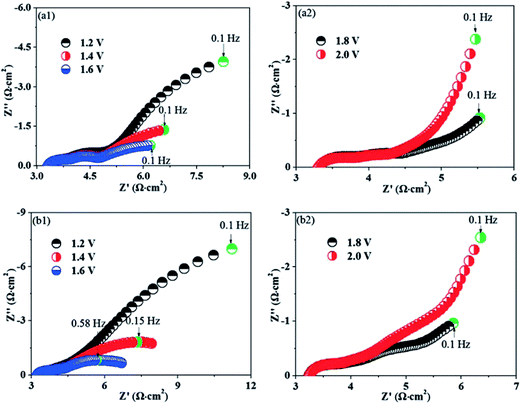 | ||
| Fig. 20 The electrochemical ac impedance spectra of La0.3Sr0.7TiO3 (LST) and (La0.3Sr0.7)0.9Ti0.9Ni0.1O3−δ (LSTN) in a mixture of 3% H2O, 5% H2 and 93% Ar at 800 °C (left).129 Reprinted with permission. | ||
4. Future prospects
Various synthetic methods to prepare the nano-structural electrodes for SOFCs were briefly reviewed in this study. Some of them did show improved performance of electrodes under various fuel conditions; however, most literature studies did not report long-term operating performances, suggesting that the durability test is required before commercializing these promising nano-structured electrodes in SOFCs. Moreover, the scale up process remains an open area for further work. Amongst the reported nano-structural approaches, the ex-solution-type method has showed some promise to mitigate the unwanted side reactions, such as the suppression of the growth of carbon in hydrocarbon fuels. However, ex-solution is strongly limited by the solubility of dopants in the host structure and their density on surfaces seems to be hard to control at the large scale production, unlike conventional composite electrodes. A few reports claim to report the synthesis of bimetallic particles by the ex-solution method, but ambiguity was raised due to the fact that the diffusion coefficient of various ions was not considered. So far, there seems to be no systematic study to quantify the amount of dopants being ex-soluted as a function of temperature. Using in situ synchrotron X-ray and neutron diffraction measurements, due to their strong penetration depth and their sensitivity, one could fill this gap. With the use of certain constrain conditions in the Rietveld refinement, a quantitative analysis of the ex-soluted particles as a function of temperature and atmosphere could be estimated. Also, the ex-solution-type cathode for SOFCs is a rather unexplored area of research. In summary, the fundamental understanding of the microstructure–property relationships of electrodes is critical for the development of next generation electrodes for SOFCs. With similar materials and preparation techniques, it is entirely possible that such a methodology may also be transferable to electrolysis SOECs application.Abbreviations
Acknowledgements
V. T. acknowledges the support from the Natural Sciences and Engineering Research Council of Canada thorough the Discovery Grants program (Grant Number: RGPIN-2016-03853). W. H. K. acknowledges the financial support from the China Spallation Neutron Source, the institute of High Energy Physics, Chinese Academy of Sciences.References
- A. D. Boyd, Int. J. Greenhouse Gas Control, 2015, 32, 81–89 CrossRef CAS.
- J. Twidell and T. Weir, Renewable Energy Resources, Taylor & Francis, 2015 Search PubMed.
- A. Atkinson, S. Barnett, R. J. Gorte, J. T. S. Irvine, A. J. McEvoy, M. Mogensen, S. C. Singhal and J. Vohs, Nat. Mater., 2004, 3, 17–27 CrossRef CAS PubMed.
- R. O'Hayre, S. W. Cha, W. Colella and F. B. Prinz, Fuel Cell Fundamentals, Wiley, 2009 Search PubMed.
- K. Huang and J. B. Goodenough, Solid Oxide Fuel Cell Technology: Principles, Performance and Operations, Elsevier Science, 2009 Search PubMed.
- J. T. S. Irvine, D. Neagu, M. C. Verbraeken, C. Chatzichristodoulou, C. Graves and M. B. Mogensen, Nat. Energy, 2016, 1, 15014 CrossRef.
- W. H. Kan and V. Thangadurai, Ionics, 2015, 21, 301–318 CrossRef CAS.
- E. D. Wachsman and K. T. Lee, Science, 2011, 334, 935–939 CrossRef CAS PubMed.
- N. Behling, Fuel Cells Current Technology Challenges and Future Research Needs, Elsevier, 1st edn, 2012 Search PubMed.
- S. P. Jiang, Int. J. Hydrogen Energy, 2012, 37, 449–470 CrossRef CAS.
- Z. Liu, B. Liu, D. Ding, M. Liu, F. Chen and C. Xia, J. Power Sources, 2013, 237, 243–259 CrossRef CAS.
- T. Sholklapper, C. Jacobson, S. Visco and L. De Jonghe, Fuel Cells, 2008, 8, 303–312 CrossRef CAS.
- E. Perry Murray and S. A. Barnett, Solid State Ionics, 2001, 143, 265–273 CrossRef CAS.
- T. Kenjo and M. Nishiya, Solid State Ionics, 1992, 57, 295–302 CrossRef CAS.
- M. J. Jørgensen, S. Primdahl, C. Bagger and M. Mogensen, Solid State Ionics, 2001, 139, 1–11 CrossRef.
- M. J. L. Østergård, C. Clausen, C. Bagger and M. Mogensen, Electrochim. Acta, 1995, 40, 1971–1981 CrossRef.
- E. V. Tsipis and V. V. Kharton, J. Solid State Electrochem., 2008, 12, 1367–1391 CrossRef CAS.
- Z. Shao and S. M. Haile, Nature, 2004, 431, 170–173 CrossRef CAS PubMed.
- J.-H. Kim and A. Manthiram, J. Mater. Chem. A, 2015, 3, 24195–24210 CAS.
- S. P. Jiang, Solid State Ionics, 2002, 146, 1–22 CrossRef CAS.
- A. Esquirol, N. P. Brandon, J. A. Kilner and M. Mogensen, J. Electrochem. Soc., 2004, 151, A1847–A1855 CrossRef CAS.
- A. V. Berenov, A. Atkinson, J. A. Kilner, E. Bucher and W. Sitte, Solid State Ionics, 2010, 181, 819–826 CrossRef CAS.
- P. S. Manning, J. D. Sirman and J. A. Kilner, Solid State Ionics, 1996, 93, 125–132 CrossRef CAS.
- T. Ishihara, H. Matsuda and Y. Takita, J. Am. Chem. Soc., 1994, 116, 3801–3803 CrossRef CAS.
- F. Abraham, J. C. Boivin, G. Mairesse and G. Nowogrocki, Solid State Ionics, 1990, 40–41, 934–937 CrossRef CAS.
- J. W. Stevenson, T. R. Armstrong, L. R. Pederson, J. Li, C. A. Lewinsohn and S. Baskaran, Solid State Ionics, 1998, 113–115, 571–583 CrossRef CAS.
- E. Djurado and M. Labeau, J. Eur. Ceram. Soc., 1998, 18, 1397–1404 CrossRef CAS.
- S. H. Chan, X. J. Chen and K. A. Khor, Solid State Ionics, 2003, 158, 29–43 CrossRef CAS.
- Y. J. Leng and S. H. Chan, Electrochem. Solid-State Lett., 2006, 9, A56–A59 CrossRef CAS.
- E. D. Wachsman, P. Jayaweera, N. Jiang, D. M. Lowe and B. G. Pound, J. Electrochem. Soc., 1997, 144, 233–236 CrossRef CAS.
- J. S. Ahn, D. Pergolesi, M. A. Camaratta, H. Yoon, B. W. Lee, K. T. Lee, D. W. Jung, E. Traversa and E. D. Wachsman, Electrochem. Commun., 2009, 11, 1504–1507 CrossRef CAS.
- J. C. Boivin and G. Mairesse, Chem. Mater., 1998, 10, 2870–2888 CrossRef CAS.
- A. Orera and P. R. Slater, Chem. Mater., 2010, 22, 675–690 CrossRef CAS.
- P. Singh and J. B. Goodenough, Energy Environ. Sci., 2012, 5, 9626–9631 CAS.
- W. H. Kan, K.-Y. Lai, A. Huq and A. Manthiram, J. Power Sources, 2016, 307, 454–461 CrossRef CAS.
- C. Xia and M. Liu, Adv. Mater., 2002, 14, 521–523 CrossRef CAS.
- H. S. Spacil, US Pat., US3503809 A, 1970.
- R. J. Gorte and J. M. Vohs, Curr. Opin. Colloid Interface Sci., 2009, 14, 236–244 CrossRef CAS.
- S. Zha, Z. Cheng and M. Liu, J. Electrochem. Soc., 2007, 154, B201–B206 CrossRef CAS.
- C. Zhang, M. E. Grass, A. H. McDaniel, S. C. DeCaluwe, F. E. Gabaly, Z. Liu, K. F. McCarty, R. L. Farrow, M. A. Linne, Z. Hussain, G. S. Jackson, H. Bluhm and B. W. Eichhorn, Nat. Mater., 2010, 9, 944–949 CrossRef CAS PubMed.
- W. C. Chueh, Y. Hao, W. Jung and S. M. Haile, Nat. Mater., 2011, 11, 155–161 CrossRef PubMed.
- M. Chen, S. Paulson, W. H. Kan, V. Thangadurai and V. Birss, J. Mater. Chem. A, 2015, 3, 22614–22626 CAS.
- L. Deleebeeck and V. Birss, Solid State Ionics, 2011, 203, 69–79 CrossRef CAS.
- Z. Gao, L. V. Mogni, E. C. Miller, J. G. Railsback and S. A. Barnett, Energy Environ. Sci., 2016, 9, 1602–1644 CAS.
- N. M. Sammes, Y. Du and R. Bove, J. Power Sources, 2005, 145, 428–434 CrossRef CAS.
- T. Suzuki, T. Yamaguchi, Y. Fujishiro and M. Awano, J. Power Sources, 2006, 160, 73–77 CrossRef CAS.
- Y. Funahashi, T. Shimamori, T. Suzuki, Y. Fujishiro and M. Awano, J. Power Sources, 2007, 163, 731–736 CrossRef CAS.
- A. Evans, A. Bieberle-Huetter, J. L. M. Rupp and L. J. Gauckler, J. Power Sources, 2009, 194, 119–129 CrossRef CAS.
- C.-W. Kwon, J.-W. Son, J.-H. Lee, H.-M. Kim, H.-W. Lee and K.-B. Kim, Adv. Funct. Mater., 2011, 21, 1154–1159 CrossRef CAS.
- S. C. Singhal and K. Kendall, High-temperature Solid Oxide Fuel Cells: Fundamentals, Design and Applications, Elsevier Science, 2003 Search PubMed.
- F. M. Figueiredo, J. A. Labrincha, J. R. Frade and F. M. B. Marques, Solid State Ionics, 1997, 101–103, 343–349 CrossRef CAS.
- H. Yokokawa, N. Sakai, T. Kawada and M. Dokiya, J. Electrochem. Soc., 1991, 138, 2719–2727 CrossRef CAS.
- J. M. Vohs and R. J. Gorte, Adv. Mater., 2009, 21, 943–956 CrossRef CAS.
- A. Samson, M. Søgaard, R. Knibbe and N. Bonanos, J. Electrochem. Soc., 2011, 158, B650–B659 CrossRef CAS.
- A. Evans, A. Bieberle-Hütter, J. L. M. Rupp and L. J. Gauckler, J. Power Sources, 2009, 194, 119–129 CrossRef CAS.
- D. Beckel, A. Bieberle-Hütter, A. Harvey, A. Infortuna, U. Muecke, M. Prestat, J. Rupp and L. Gauckler, J. Power Sources, 2007, 173, 325–345 CrossRef CAS.
- L. Dieterle, P. Bockstaller, D. Gerthsen, J. Hayd, E. Ivers-Tiffée and U. Guntow, Adv. Energy Mater., 2011, 1, 249–258 CrossRef CAS.
- A. J. Darbandi and H. Hahn, Solid State Ionics, 2009, 180, 1379–1387 CrossRef CAS.
- A. Evans, A. Bieberle-Hütter, H. Galinski, J. L. Rupp, T. Ryll, B. Scherrer, R. Tölke and L. J. Gauckler, Monatsh. Chem., 2009, 140, 975–983 CrossRef CAS.
- Y. Tao, J. Shao, W. G. Wang and J. Wang, Fuel Cells, 2009, 9, 679–683 CrossRef CAS.
- W. G. Wang and M. Mogensen, Solid State Ionics, 2005, 176, 457–462 CrossRef CAS.
- C. Peters, A. Weber and E. Ivers-Tiffée, J. Electrochem. Soc., 2008, 155, B730–B737 CrossRef CAS.
- J. Højberg and M. Søgaard, Electrochem. Solid-State Lett., 2011, 14, B77–B79 CrossRef.
- F. Zhao, R. Peng and C. Xia, Mater. Res. Bull., 2008, 43, 370–376 CrossRef CAS.
- M. Shah and S. A. Barnett, Solid State Ionics, 2008, 179, 2059–2064 CrossRef CAS.
- Y.-F. Sun, J.-H. Li, L. Cui, B. Hua, S.-H. Cui, J. Li and J.-L. Luo, Nanoscale, 2015, 7, 11173–11181 RSC.
- D. Ding, X. Li, S. Y. Lai, K. Gerdes and M. Liu, Energy Environ. Sci., 2014, 7, 552–575 CAS.
- Z. Jiang, C. Xia and F. Chen, Electrochim. Acta, 2010, 55, 3595–3605 CrossRef CAS.
- K. K. Hansen, M. Wandel, Y. L. Liu and M. Mogensen, Electrochim. Acta, 2010, 55, 4606–4609 CrossRef CAS.
- R. J. H. Voorhoeve, D. W. Johnson, J. P. Remeika and P. K. Gallagher, Science, 1977, 195, 827–833 CAS.
- Y. Nishihata, J. Mizuki, T. Akao, H. Tanaka, M. Uenishi, M. Kimura, T. Okamoto and N. Hamada, Nature, 2002, 418, 164–167 CrossRef CAS PubMed.
- M. Uenishi, H. Tanaka, I. Tan, M. Taniguchi, N. Kajita, M. Kimura, K. Narita and H. Suzuki, AutoTechnology, 2007, 7, 44–47 Search PubMed.
- H. Tanaka, M. Taniguchi, M. Uenishi, N. Kajita, I. Tan, Y. Nishihata, J. i. Mizuki, K. Narita, M. Kimura and K. Kaneko, Angew. Chem., Int. Ed., 2006, 45, 5998–6002 CrossRef CAS PubMed.
- D. Neagu, G. Tsekouras, D. N. Miller, H. Menard and J. T. S. Irvine, Nat. Chem., 2013, 5, 916–923 CrossRef CAS PubMed.
- H. J. T. Ellingham, J. Soc. Chem. Ind., 1944, 63, 125–160 CrossRef CAS.
- D. Ding, M. Liu and M. Liu, ECS Trans., 2013, 57, 1801–1810 CrossRef.
- R. Kiebach, C. Knöfel, F. Bozza, T. Klemensø and C. Chatzichristodoulou, J. Power Sources, 2013, 228, 170–177 CrossRef CAS.
- X. Lou, Z. Liu, S. Wang, Y. Xiu, C. P. Wong and M. Liu, J. Power Sources, 2010, 195, 419–424 CrossRef CAS.
- T. Z. Sholklapper, C. Lu, C. P. Jacobson, S. J. Visco and L. C. De Jonghe, Electrochem. Solid-State Lett., 2006, 9, A376–A378 CrossRef CAS.
- S. Lee, N. Miller, H. Abernathy, K. Gerdes and A. Manivannan, J. Electrochem. Soc., 2011, 158, B735–B742 CrossRef CAS.
- J. D. Nicholas and S. A. Barnett, J. Electrochem. Soc., 2010, 157, B536–B541 CrossRef CAS.
- J. M. Serra and H.-P. Buchkremer, J. Power Sources, 2007, 172, 768–774 CrossRef CAS.
- A. J. Van Dillen, R. J. Terörde, D. J. Lensveld, J. W. Geus and K. P. De Jong, J. Catal., 2003, 216, 257–264 CrossRef CAS.
- P.-P. Jiang, S.-H. Zhang, Y.-L. Guo, Y. Guo, X.-Y. Wang and G.-Z. Lu, J. Inorg. Mater., 2004, 19, 634–640 CAS.
- R. Küngas, J.-S. Kim, J. M. Vohs and R. J. Gorte, J. Am. Ceram. Soc., 2011, 94, 2220–2224 CrossRef.
- H. Zhang and W. Yang, Chem. Commun., 2007, 4215–4217 RSC.
- A. J. Samson, M. Søgaard, P. Hjalmarsson, J. Hjelm, N. Bonanos, S. P. V. Foghmoes and T. Ramos, Fuel Cells, 2013, 13, 511–519 CrossRef CAS.
- V. Dusastre and J. A. Kilner, Solid State Ionics, 1999, 126, 163–174 CrossRef CAS.
- E. Perry Murray, M. J. Sever and S. A. Barnett, Solid State Ionics, 2002, 148, 27–34 CrossRef CAS.
- A. Petric, P. Huang and F. Tietz, Solid State Ionics, 2000, 135, 719–725 CrossRef CAS.
- M. Sase, D. Ueno, K. Yashiro, A. Kaimai, T. Kawada and J. Mizusaki, J. Phys. Chem. Solids, 2005, 66, 343–348 CrossRef CAS.
- M. Backhaus-Ricoult, Solid State Ionics, 2006, 177, 2195–2200 CrossRef CAS.
- M. Backhaus-Ricoult, K. Adib, T. S. Clair, B. Luerssen, L. Gregoratti and A. Barinov, Solid State Ionics, 2008, 179, 891–895 CrossRef CAS.
- D. Chen, G. Yang, F. Ciucci, M. O. Tade and Z. Shao, J. Mater. Chem. A, 2014, 2, 1284–1293 CAS.
- Y. Zhou, B. An, Y. Guo, R. Ran and Z. Shao, Electrochem. Commun., 2009, 11, 2216–2219 CrossRef CAS.
- T. Nagai, W. Ito and T. Sakon, Solid State Ionics, 2007, 177, 3433–3444 CrossRef CAS.
- W. Zhou, Z. Shao, R. Ran, W. Jin and N. Xu, Chem. Commun., 2008, 5791–5793, 10.1039/b813327a.
- P. Hjalmarsson, J. Hallinder and M. Mogensen, J. Solid State Electrochem., 2012, 16, 2759–2766 CrossRef CAS.
- A. J. Samson, M. Søgaard and N. Bonanos, Electrochem. Solid-State Lett., 2012, 15, B54–B56 CrossRef CAS.
- L. Dieterle, P. Bockstaller, D. Gerthsen, J. Hayd, E. Ivers-Tiffée and U. Guntow, Adv. Energy Mater., 2011, 1, 249–258 CrossRef CAS.
- N. Imanishi, R. Ohno, K. Murata, A. Hirano, Y. Takeda, O. Yamamoto and K. Yamahara, Fuel Cells, 2009, 9, 215–221 CrossRef CAS.
- E. Mutoro, E. J. Crumlin, M. D. Biegalski, H. M. Christen and Y. Shao-Horn, Energy Environ. Sci., 2011, 4, 3689–3696 CAS.
- M. Sase, K. Yashiro, K. Sato, J. Mizusaki, T. Kawada, N. Sakai, K. Yamaji, T. Horita and H. Yokokawa, Solid State Ionics, 2008, 178, 1843–1852 CrossRef CAS.
- M. J. Gadre, Y.-L. Lee and D. Morgan, Phys. Chem. Chem. Phys., 2012, 14, 2606–2616 RSC.
- J. W. Han and B. Yildiz, Energy Environ. Sci., 2012, 5, 8598–8607 CAS.
- E. J. Crumlin, E. Mutoro, S.-J. Ahn, G. J. la O’, D. N. Leonard, A. Borisevich, M. D. Biegalski, H. M. Christen and Y. Shao-Horn, J. Phys. Chem. Lett., 2010, 1, 3149–3155 CrossRef CAS.
- J. Hayd, H. Yokokawa and E. Ivers-Tiffée, J. Electrochem. Soc., 2013, 160, F351–F359 CrossRef CAS.
- F. A. Kroger, Annu. Rev. Mater. Sci., 1977, 7, 449–475 CrossRef.
- J. C. Ruiz-Morales, J. Canales-Vázquez, C. Savaniu, D. Marrero-López, W. Zhou and J. T. S. Irvine, Nature, 2006, 439, 568–571 CrossRef CAS PubMed.
- D. Neagu, T.-S. Oh, D. N. Miller, H. Menard, S. M. Bukhari, S. R. Gamble, R. J. Gorte, J. M. Vohs and J. T. S. Irvine, Nat. Commun., 2015, 6(8120), 1–8 Search PubMed.
- G. Xiao, S. Wang, Y. Lin, Y. Zhang, K. An and F. Chen, ACS Appl. Mater. Interfaces, 2014, 6, 19990–19996 CAS.
- Q. Qin, G. Wu, S. Chen, W. Doherty, K. Xie and Y. Wu, Electrochim. Acta, 2014, 127, 215–227 CrossRef CAS.
- D. Papargyriou and J. T. S. Irvine, Solid State Ionics, 2016, 288, 120–123 CrossRef CAS.
- H. Yoon, J. Zou, N. M. Sammes and J. Chung, Int. J. Hydrogen Energy, 2015, 40, 10985–10993 CrossRef CAS.
- R. Thalinger, M. Gocyla, M. Heggen, B. Klötzer and S. Penner, J. Phys. Chem. C, 2015, 119, 22050–22056 CAS.
- L. Yang, Y. Choi, W. Qin, H. Chen, K. Blinn, M. Liu, P. Liu, J. Bai, T. A. Tyson and M. Liu, Nat. Commun., 2011, 2, 357 CrossRef PubMed.
- W. Qi, K. Xie, M. Liu, G. Wu, Y. Wang, Y. Zhang and Y. Wu, RSC Adv., 2014, 4, 40494–40504 RSC.
- H. Wei, K. Xie, J. Zhang, Y. Zhang, Y. Wang, Y. Qin, J. Cui, J. Yan and Y. Wu, Sci. Rep., 2014, 4, 5156 CAS.
- J. Liu, P. Han, M. Dong, G. Fan, G. Qiao and J. Yang, Phys. B, 2012, 407, 891–895 CrossRef CAS.
- A. Refaat Ali, S. A. Mahmoud, Z. M. Farid and K. Atef, Phys. Status Solidi A, 1998, 165, 377–387 CrossRef CAS.
- A. Seko, N. Odagaki, S. R. Nishitani, I. Tanaka and H. Adachi, Mater. Trans., 2004, 45, 1978–1981 CrossRef CAS.
- T.-S. Oh, E. K. Rahani, D. Neagu, J. T. S. Irvine, V. B. Shenoy, R. J. Gorte and J. M. Vohs, J. Phys. Chem. Lett., 2015, 6, 5106–5110 CrossRef CAS PubMed.
- W. H. Kan, P. Dong, J.-S. Bae, S. Adams and V. Thangadurai, Solid State Ionics, 2016, 290, 90–97 CrossRef CAS.
- W. H. Kan, A. Huq and A. Manthiram, Chem. Mater., 2016, 28, 1832–1837 CrossRef CAS.
- W. H. Kan, A. Huq and A. Manthiram, Chem. Mater., 2015, 27, 7729–7733 CrossRef CAS.
- W. H. Kan, A. Huq and A. Manthiram, Chem. Commun., 2015, 51, 10447–10450 RSC.
- M. Sale and M. Avdeev, J. Appl. Crystallogr., 2012, 45, 1054–1056 CrossRef CAS.
- Y.-F. Sun, X.-W. Zhou, Y. Zeng, B. S. Amirkhiz, M.-N. Wang, L.-Z. Zhang, B. Hua, J. Li, J.-H. Li and J.-L. Luo, J. Mater. Chem. A, 2015, 3, 22830–22838 CAS.
- J. Zhang, K. Xie, Y. Gan, G. Wu, B. Ding, Y. Zhang and Y. Wu, New J. Chem., 2014, 38, 3434–3442 RSC.
Footnote |
| † These authors contributed equally. |
| This journal is © The Royal Society of Chemistry 2016 |


