 Open Access Article
Highly durable Pt nanoparticle-supported carbon catalysts for the oxygen reduction reaction tailored by using an ionic liquid thin layer†
Kazuki
Yoshii
a,
Keisuke
Yamaji
a,
Tetsuya
Tsuda
*a,
Hiroaki
Matsumoto
b,
Takeshi
Sato
b,
Reiko
Izumi
a,
Tsukasa
Torimoto
c and
Susumu
Kuwabata
*a
aDepartment of Applied Chemistry, Graduate School of Engineering, Osaka University, 2-1 Yamada-oka, Suita, Osaka 565-0871, Japan. E-mail: ttsuda@chem.eng.osaka-u.ac.jp; kuwabata@chem.eng.osaka-u.ac.jp
bScience and Medical Systems Business Group, Hitachi High-Technologies Corporation, Hitachinaka, Ibaraki 312-0057, Japan
cDepartment of Crystalline Materials Science, Graduate School of Engineering, Nagoya University, Furo-cho, Chikusa-ku, Nagoya, Aichi 464-8603, Japan
First published on 4th July 2016
Abstract
Pt nanoparticles monodispersed in an ionic liquid (IL), which can be readily prepared by magnetron sputtering onto an IL, are a key material for tailoring highly durable Pt nanoparticle-supported carbon electrocatalysts, e.g., Pt nanoparticle-supported single-walled carbon nanotubes (Pt-SWCNTs) and Vulcan® XC-72 (Pt-Vulcan®), for the electrochemical oxygen reduction reaction. The durability largely surpasses that of one of the commercially available Vulcan® XC-72-based catalysts, TEC10V30E. The differences were very obvious from the results of electrochemical measurements, ex situ TEM observation, and in situ SEM/STEM observation; that is, considerable damage by carbon corrosion was recognized for the TEC10V30E, but it was not the case for the Pt-SWCNT and Pt-Vulcan®. The unexpected high durability should be due to the suppression of carbon corrosion by the ionic liquid thin layer that exists between the Pt nanoparticles and carbon support.
1. Introduction
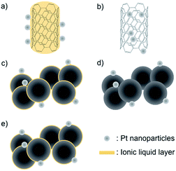
Polymer electrolyte membrane (PEM) fuel cells are an attractive electric power generation system for mobile and stationary applications because of their high energy conversion efficiency and environmental friendliness.1–3 Nevertheless, the cost per watt generated by the fuel cell system and the difficulty of maintaining its long-term operation are big hurdles for popularizing it in our daily life. In PEM fuel cells, Pt nanoparticle-supported conductive carbons, such as Ketjen black EC and Vulcan® XC-72, are commonly used as cathode electrocatalysts.4 The deterioration of these electrocatalysts, which is highly correlated with the long-term operation hurdle above, is one of the key issues to solve. The deterioration is caused by electrochemical corrosion (oxidation) of the carbon support at the cathode,5–8 and, furthermore, the corrosion is particularly accelerated during start-up and shutdown operations when the local cathode potential can reach voltages as high as 1.5 V.9–11 Under these conditions, the carbon material is oxidized to carbon dioxide and/or carbon monoxide. This also leads to the aggregation and migration of Pt nanoparticles, as well as their detachment from the carbon support. Such deterioration of the cathode electrocatalyst in a PEM fuel cell has been observed by a combination of electrochemical measurements, spectroscopic analyses, and electron microscopic observations.12–17 Variations in the nanostructural morphology have been commonly observed by using an ex situ transmission electron microscopy (TEM) technique. Now, direct observation of the deterioration of the electrocatalyst is possible using a special in situ SEM/STEM technique that includes heating under an air-injection atmosphere.18 This in situ technique has revealed that the carbon support needs to be anti-corrosive in nature in order to enhance the durability of the cathode catalysts. In fact, novel carbon materials such as carbon nanotubes and graphene have been studied as the catalyst support to improve the durability of the Pt catalyst,19–22 as they offer corrosion resistance and have special electronic and mechanical properties. One thing to take into consideration though is that it is difficult to support Pt nanoparticles onto these carbon materials without breaking down the sp2 structure due to their surface inertness.23 We recently found that various metal nanoparticles, prepared by metal magnetron sputtering onto an ionic liquid (IL),24,25 can be easily supported by carbon materials by heat treatment without the requirement of any further process,26–31e.g., glassy carbon (GC), highly oriented pyrolytic carbon (HOPG), and single-walled carbon nanotubes (SWCNTs), and thus concluded that the IL works as a glue to support the Pt nanoparticles onto these materials.30 Very recently, Su et al. proposed a similar idea, namely that a very thin IL layer could be formed on a nanocarbon material via an entrapping effect.32 While the Pt-supported SWCNTs (Pt-SWCNTs) prepared by our approach show a favorable electrocatalytic activity toward the oxygen reduction reaction (ORR),30 there is no information about their durability during continuous operation or about the effect of the IL between the Pt nanoparticles and carbon supports. In this study, five types of electrocatalysts: Pt-SWCNTs, Pt-supported SWCNTs prepared by a conventional method (Pt-SWCNTsconv), Pt-supported Vulcan® obtained by a method similar to that for the Pt-SWCNTs (Pt-Vulcan®), IL-modified TEC10V30E (TEC10V30E-IL), and commercially available TEC10V30E were investigated to reveal the points described above. Schematic illustrations of these electrocatalysts are given in Fig. 1a–e. Only two samples, Pt-SWCNTs and Pt-Vulcan®, had an IL thin layer between the Pt nanoparticles and the carbon support.2. Experimental
2.1 Materials
The ionic liquid (IL), N,N,N-trimethyl-N-propylammonium bis(trifluoromethanesulfonyl)amide ([N1,1,1,3][Tf2N]), was purchased from Kanto Chemical (specially manufactured grade). In order to remove a trace of Br anions derived from the chemical precursor, the dichloromethane phase containing the IL was washed repeatedly with reverse osmosis (RO) water (18.2 MΩ cm) until the water phase was found to contain no bromide as determined by the addition of a few drops of a silver nitrate solution. The dichloromethane and remaining water were removed by stirring under vacuum conditions at 373 K for 24 h. Single-walled carbon nanotubes (SWCNTs) and carbon black (Vulcan® XC-72) were purchased from Meijo Nano Carbon and Cabot, respectively. Nafion® solution (5 wt%) was purchased from Sigma-Aldrich. TEC10V30E, which is a commercially available Pt nanoparticle-supported carbon catalyst, was purchased from Tanaka Kikinzoku Kogyo. Except the IL, all chemicals were used as received.2.2 Preparation of Pt nanoparticle-supported carbon materials
The soda glass (2.5 cm × 2.5 cm), on which [N1,1,1,3][Tf2N] (0.4 mL) was spread, was placed in a Cressington108 auto SE sputter coater. A polycrystalline Pt plate target (ϕ 5.7 cm, 99.98%) was placed 4.5 cm above the glass plate. Sputter deposition onto [N1,1,1,3][Tf2N] was conducted with a sputter current of 40 mA in a dry Ar (99.999%) atmosphere whose pressure did not exceed 7 ± 1 Pa. The sputtering was carried out in direct current (DC) mode at room temperature (298 ± 2 K). SWCNTs (1.5 mg) or Vulcan® (2.0 mg) were mixed with 0.4 mL of Pt-sputtered [N1,1,1,3][Tf2N] in a vial and agitated for 10 h to make a homogeneous dispersion state. The resulting mixture was heated at 573 K for 5 h. Similarly, IL-modified TEC10V30E (TEC10V30E-IL) was prepared by agitating TEC10V30E (2.5 mg) and [N1,1,1,3][Tf2N]. The obtained Pt-SWCNT, Pt-Vulcan®, and TEC10V30E-IL were rinsed with acetonitrile several times, followed by vacuum drying for a few hours in vacuo. The Pt-SWCNTconv was prepared based on a previous report.332.3 Characterization
The Pt nanoparticle-supported carbon electrocatalysts used in this study were observed using a HITACHI H-7650 transmission electron microscope (TEM) with an acceleration voltage of 100 kV. The Pt contents in the carbon materials were identified using a Shimadzu ICPS-7510 inductively coupled plasma atomic emission spectrometer (ICP-AES). The Pt nanoparticles on the carbon composites were dissolved in hot aqua regia prior to the ICP-AES measurements. The durability of the Pt catalysts was electromicroscopically examined under air injection up to 4–10 Pa (56–60% RH (relative humidity), 298–300 K) by in situ scanning electron microscopy (SEM) and scanning transmission electron microscopy (STEM) analyses with a Hitachi HF-3300 cold field-emission environmental TEM system. The detailed setup for the in situ analyses is described in a previous study.18 The specimens were heated at 473 K during the durability test.2.4 Electrochemical measurement
Electrocatalytic activities of the Pt-SWCNT, Pt-SWCNTconv, Pt-Vulcan®, TEC10V30E, and TEC10V30E-IL were examined with a Hokuto Denko HZ-7000 potentiostat/galvanostat controlled with a laptop computer. The electrochemical experiments were conducted using a three-electrode cell at room temperature. A glassy carbon (GC) rotating disk electrode (surface area: 0.196 cm2, Pine Instruments) was used as the working electrode. The GC electrode was polished to a mirror finish with a slurry of 0.06 μm alumina and then rinsed with RO water and dry ethanol before use. The catalyst ink was prepared by ultrasonically dispersing 1.0 mg of Pt–carbon materials described above in 2-propanol (0.2 mL) for 30 min. 5 μL of the ink was uniformly spread onto GC and the 2-propanol in the ink was slowly evaporated in air. Then, the GC disk was covered with 5 μL of Nafion® solution (0.2 wt%) diluted with 2-propanol to fix the catalyst on GC robustly. The obtained working electrode was set in a Pine Instruments AFMSRCE electrode rotator for the measurements. A platinum mesh was used as the counter electrode. A silver/silver chloride double-junction electrode immersed in saturated-KCl aqueous solution was used as the reference electrode. All potential values in this paper are referenced to the reversible hydrogen electrode (RHE). 0.1 M HClO4 aqueous solution was used as the electrolyte. Before the measurement of their electrocatalytic activities, electrochemical cleaning of the working electrode was performed by fifty potential sweeps between 0.05 and 1.2 V (vs. RHE) at 50 mV s−1 under a nitrogen atmosphere. The electrochemical surface area (ECSA) of Pt nanoparticles was determined by hydrogen adsorption or desorption coulombic charge in the cyclic voltammogram under a nitrogen atmosphere after subtracting double layer charge current. The value of the ECSA was calculated from the equation given by | (1) |
The durability of the electrocatalysts was estimated by a standard degradation test recommended by Fuel Cell Commercialization Conference of Japan (FCCJ).35,36 This test overloads a cathode for a PEM fuel cell system by potential sweeps between 1.0 and 1.5 V (vs. RHE) at 500 mV s−1. Under this condition, carbon corrosion proceeds with ease. In other words, we can evaluate the durability of the cathode catalyst electrochemically in a short time. In order to obtain more insight into the deterioration behavior, the catalytic activity retention rate for the ECSA was estimated by the following equation (eqn (2)):
 | (2) |
Catalytic activity retention rate for mass activity was obtained by a similar equation (eqn (3)):
 | (3) |
3. Results and discussion
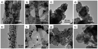
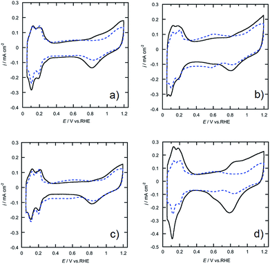
The morphologies of the Pt-SWCNT, Pt-SWCNTconv, Pt-Vulcan®, and TEC10V30E were observed by TEM to know the dispersed state of Pt nanoparticles (Fig. 2a–d). The Pt nanoparticles uniformly existed on the Pt-SWCNT and Pt-Vulcan®, and their mean particle size was ca. 3.6–3.7 nm. On the other hand, the Pt nanoparticles agglomerated were partially recognized on the Pt-SWCNTconv and TEC10V30E, but their mean particle size (ca. 2.6–2.8 nm) was smaller than that of the aforementioned two samples. The Pt loading amounts for all the samples were ca. 26–32 wt%. The detailed information is given in Table 1. Fig. 3a–d show cyclic voltammograms (CVs) recorded at the Pt-supported electrocatalysts in 0.1 M HClO4 solution deaerated with N2 at room temperature before and after the potential cycle test which simulates an actual fuel cell operation.9 At all the electrocatalysts, redox waves for the hydrogen adsorption/desorption and the Pt-oxide formation/reduction appeared at potentials ranging from 0.10 to 0.35 V (vs. RHE) and from 0.80 to 1.20 V, respectively. As is well known, a pair of ill-defined peaks that are assignable to the redox reaction of quinone and hydroquinone moieties appear at around 0.60 V due to the oxidation of the carbon support.37 Especially at the Pt-SWCNTconv and TEC10V30E, the undesirable peaks became clearer after the cycle test. Also, the changes in the electrochemical surface area (ECSA) during the potential cycle test give important information on whether the carbon material has favorable characteristics as a carbon support for the electrocatalysts or not. The data are shown in Fig. 4a as a function of the cycle number. The ECSA decreased with increasing cycle number. But, it increased at the initial several thousand cycles for the Pt-SWCNT. This unexpected behavior would be caused by the slight residual IL on the Pt nanoparticles rinsed during the test. The Pt-SWCNT showed the highest maximum ECSA owing to keeping a favorable Pt nanoparticle dispersed state. In order to obtain more insight into the behavior, the data are converted to the catalytic activity retention rate, which directly shows the catalytic durability, by the expression, eqn (3), in the Experimental section. The data are graphically displayed in Fig. 4b and all the data obtained by the cycle test are summarized in Table 1. The order of the catalytic activity retention rate calculated from the ECSA data after 15![[thin space (1/6-em)]](https://www.rsc.org/images/entities/char_2009.gif) 000 cycles is as follows: Pt-SWCNT, Pt-Vulcan®, Pt-SWCNTconv, and TEC10V30E. As the Pt-SWCNT was prepared without laborious pretreatment such as an oxidative treatment, it maintains a pristine structure on the surface. The pristine SWCNT composed of only sp2 carbon is inherently more physicochemically stable than carbon black and acid-pretreated SWCNTs that have various functional groups such as hydroxyl or carboxyl groups.38 Therefore, it is considered that the Pt-SWCNT has a strong resistance toward the corrosion during the potential cycle test leading to the inhibition of the Pt nanoparticle aggregation, migration, and detachment from the catalysts. What makes the result even more interesting is that Pt-Vulcan® has a higher catalytic activity retention rate compared with TEC10V30E, although these two electrocatalysts use the same carbon support (Vulcan® XC-72). It is commonly believed that the corrosion of Vulcan® proceeds easily during the potential cycle test through the oxidation of functional groups to carbon dioxide or carbon monoxide.4 The difference between Pt-Vulcan® and TEC10V30E is that an IL thin layer exists on the carbon surface or not. To clarify the importance of the location where the IL exists on the carbon support, we applied the IL to the TEC10V30E by the approach described in the Experimental section. The resulting material, TEC10V30E-IL, was covered with a thin IL layer, but Pt nanoparticles were directly in contact with the carbon support (Fig. 1e). The variation in the catalytic activity retention rate for the TEC10V30E-IL was slightly worse compared to that for the original TEC10V30E (Fig. S1†). It means that the modification of the as-prepared Pt supported catalyst by using the IL is ineffective in preventing the degradation of the catalyst and that the IL has to exist between the Pt nanoparticles and carbon support to enhance the durability.
000 cycles is as follows: Pt-SWCNT, Pt-Vulcan®, Pt-SWCNTconv, and TEC10V30E. As the Pt-SWCNT was prepared without laborious pretreatment such as an oxidative treatment, it maintains a pristine structure on the surface. The pristine SWCNT composed of only sp2 carbon is inherently more physicochemically stable than carbon black and acid-pretreated SWCNTs that have various functional groups such as hydroxyl or carboxyl groups.38 Therefore, it is considered that the Pt-SWCNT has a strong resistance toward the corrosion during the potential cycle test leading to the inhibition of the Pt nanoparticle aggregation, migration, and detachment from the catalysts. What makes the result even more interesting is that Pt-Vulcan® has a higher catalytic activity retention rate compared with TEC10V30E, although these two electrocatalysts use the same carbon support (Vulcan® XC-72). It is commonly believed that the corrosion of Vulcan® proceeds easily during the potential cycle test through the oxidation of functional groups to carbon dioxide or carbon monoxide.4 The difference between Pt-Vulcan® and TEC10V30E is that an IL thin layer exists on the carbon surface or not. To clarify the importance of the location where the IL exists on the carbon support, we applied the IL to the TEC10V30E by the approach described in the Experimental section. The resulting material, TEC10V30E-IL, was covered with a thin IL layer, but Pt nanoparticles were directly in contact with the carbon support (Fig. 1e). The variation in the catalytic activity retention rate for the TEC10V30E-IL was slightly worse compared to that for the original TEC10V30E (Fig. S1†). It means that the modification of the as-prepared Pt supported catalyst by using the IL is ineffective in preventing the degradation of the catalyst and that the IL has to exist between the Pt nanoparticles and carbon support to enhance the durability.
| Catalyst | Mean particle size (nm) | Loading amount of Pt (wt%) | Initial ECSA (m2 g−1) | Maximum ECSA (m2 g−1) | ECSA after 15![[thin space (1/6-em)]](https://www.rsc.org/images/entities/char_2009.gif) 000 cycles (m2 g−1) 000 cycles (m2 g−1) |
Catalytic activity retention rate for the ECSAa after 15![[thin space (1/6-em)]](https://www.rsc.org/images/entities/char_2009.gif) 000 cycles (%) 000 cycles (%) |
|---|---|---|---|---|---|---|
| a The catalytic activity retention rate was estimated by eqn (2). b The values show the standard deviation. | ||||||
| Pt-SWCNTs | 3.7 (0.8)b | 25.6 | 63.1 | 66.4 | 49.5 | 75 |
| Pt-SWCNTsconv | 2.8 (0.9)b | 29.5 | 44.3 | 44.3 | 18.5 | 41 |
| Pt-Vulcan® | 3.6 (0.9)b | 32.4 | 51.4 | 51.4 | 34.2 | 67 |
| TEC10V30E | 2.6 (0.7)b | 28.7 | 57.4 | 57.4 | 25.2 | 44 |
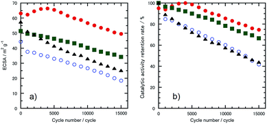 | ||
| Fig. 4 Variation in (a) the ECSA and (b) catalytic activity retention rate for the ECSA estimated from Fig. 2a as a function of cycle number. The electrocatalysts were (●) Pt-SWCNT, (○) Pt-SWCNTconv, (■) Pt-Vulcan®, and (▲) TEC10V30E. | ||
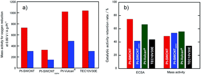
Because electrocatalytic mass activity is another important factor, the mass activity for the electrocatalysts prepared in this research for the ORR before and after the potential cycle test was measured by rotating disk electrode (RDE)-linear sweep voltammetry in an anodic direction, as shown in Fig. S2.† We have already revealed that the electrochemical ORR proceeds at the Pt-SWCNT by a four-electron reduction reaction.30 The onset potentials of the ORR recorded at the Pt-SWCNT and Pt-Vulcan® were almost unchanged even after the test of 15![[thin space (1/6-em)]](https://www.rsc.org/images/entities/char_2009.gif) 000 cycles. In order to conduct quantitative evaluation, the mass activity was calculated from the reduction current at 0.80 V before and after the potential cycle test (Fig. 5a). The mass activity decreased without exception. However, as shown in Fig. 5b, the degree of the catalytic activity retention rate for the mass activity calculated by eqn (2) varied a great deal depending on the electrocatalysts. Deterioration of the Pt-SWCNT and Pt-Vulcan® is obviously suppressed compared to the Pt-SWCNTconv and TEC10V30E. It is essential to know the morphology change of the catalysts after the potential cycle test to deduce the deterioration mechanism. Fig. 2e–h show TEM images of the Pt-SWCNT, Pt-SWCNTconv, Pt-Vulcan® and TEC10V30E after the potential cycle test. With regard to the Pt-SWCNT and Pt-Vulcan®, Pt nanoparticles remained on the carbon supports while aggregation behavior of the Pt nanoparticles was slightly recognized. Interestingly, the grain boundary of the carbon black used for Pt-Vulcan® was sustained. However, as for the TEC10V30E, most Pt nanoparticles and grain boundary disappeared. It coincides with previous reports.2,8 Pt nanoparticles on the Pt-SWCNTconv severely aggregated after the cycle test. These results strongly suggest that the IL that exists at the interface between the Pt nanoparticles and carbon support is a key to enhance catalytic durability.
000 cycles. In order to conduct quantitative evaluation, the mass activity was calculated from the reduction current at 0.80 V before and after the potential cycle test (Fig. 5a). The mass activity decreased without exception. However, as shown in Fig. 5b, the degree of the catalytic activity retention rate for the mass activity calculated by eqn (2) varied a great deal depending on the electrocatalysts. Deterioration of the Pt-SWCNT and Pt-Vulcan® is obviously suppressed compared to the Pt-SWCNTconv and TEC10V30E. It is essential to know the morphology change of the catalysts after the potential cycle test to deduce the deterioration mechanism. Fig. 2e–h show TEM images of the Pt-SWCNT, Pt-SWCNTconv, Pt-Vulcan® and TEC10V30E after the potential cycle test. With regard to the Pt-SWCNT and Pt-Vulcan®, Pt nanoparticles remained on the carbon supports while aggregation behavior of the Pt nanoparticles was slightly recognized. Interestingly, the grain boundary of the carbon black used for Pt-Vulcan® was sustained. However, as for the TEC10V30E, most Pt nanoparticles and grain boundary disappeared. It coincides with previous reports.2,8 Pt nanoparticles on the Pt-SWCNTconv severely aggregated after the cycle test. These results strongly suggest that the IL that exists at the interface between the Pt nanoparticles and carbon support is a key to enhance catalytic durability.
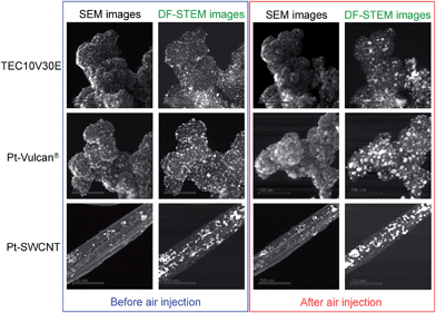
In order to obtain solid evidence for supporting our idea, we conducted durability tests for typical Pt catalysts used in this study, TEC10V30E, Pt-Vulcan®, and Pt-SWCNT, by using a brand-new in situ SEM/STEM observation technique.18 According to previous articles,4,16 carbon corrosion of the Pt particle-supported carbon cathode catalyst for a PEM fuel cell system proceeds by electrochemical carbon support combustion, and the unfavorable combustion reaction is enhanced by Pt nanoparticles. A similar combustion reaction can be replicated in the in situ SEM/STEM system under air injection without the electrode reaction, but the catalyst must be heated. Fig. 6 shows SEM and annular dark-field STEM (DF-STEM) images of TEC10V30E, Pt-Vulcan®, and Pt-SWCNT before and after low-humidity air injection for the durability tests. These images shown were captured from video clips of the in situ SEM and STEM observation. The information on the surface morphology of the Pt catalysts and on the coalescence behavior of the Pt nanoparticles on the carbon matrix can be obtained from the SEM image. In contrast, by the DF-STEM observation, even the coalescence behavior that occurs in the carbon matrix and at the behind side can be observed clearly. Combination of these two approaches enables us to directly give a conclusive answer to the question, that is, why do the Pt-Vulcan® and Pt-SWCNT prepared in this investigation show a long catalyst life? If the three Pt catalysts were heated at 473 K under high vacuum conditions (5.75 × 10⁻⁵ Pa), the morphology did not alter during the observation, and the Pt nanoparticles maintained a homogeneously dispersed state on the carbon support (Fig. S3–S5†). It means that the catalysts are stable under such conditions. During the air injection, carbon corrosion of TEC10V30E was recognized as reported in previous paper (Fig. 6).18 In the SEM image, most Pt nanoparticles disappeared and many holes appeared at the site of the original particles. The DF-STEM image indicated that the Pt nanoparticles moved into any part of the carbon matrix with their agglomeration. In light of these results, the carbon corrosion by the combustion reaction is initiated at the Pt nanoparticle|carbon support phase boundary. For the Pt-Vulcan® and Pt-SWCNT, as shown in Fig. 6, Pt nanoparticles remained even after air injection experiments but some migrate and aggregate on or in the carbon supports. The Pt-SWCNT showed a better corrosion resistance than the two other catalysts due to the chemically inert basal surface of the SWCNT without functional groups. A major variation in the catalyst was only Pt nanoparticle aggregation. What is notable is that the carbon corrosion of the Pt-Vulcan® is also suppressed compared with TEC10V30E, i.e., more Pt nanoparticles existed on the Pt-Vulcan® with fewer holes after the test. All the details of each carbon corrosion behavior can be visually understood from the video clips (Movies S1–S3†), which have been uploaded on the website of this journal.
4. Conclusions
In this study, highly durable electrocatalysts, Pt-Vulcan® and Pt-SWCNT, for the ORR were readily prepared by agitating the Pt nanoparticles monodispersed in the IL and carbon support at 573 K for 5 h. Electrochemical experiments and in situ SEM and DF-STEM observations revealed that the thin IL layer between the Pt nanoparticles and carbon support directly relates to the durability enhancement. The most important finding is that it is possible to give anti-corrosive nature to the commonly used carbon support, e.g., Vulcan®, with ease by using our approach. The Pt-Vulcan® substantially outperformed a commercially available electrocatalyst with the same carbon matrix in terms of durability. We believe that this material tailoring process will be a new approach for designing cathode catalysts for PEM fuel cell systems.Acknowledgements
K. Y. expresses his special thanks for the Research Fellowship Program for Young Scientists, Japan Society for the Promotion of Science (JSPS). Part of this research was supported by Grant-in-Aid for Scientific Research, Grant Numbers 15H03591, 15K13287, 15H2202, 16H06507 from Japanese Ministry of Education, Culture, Sports, Science and Technology (MEXT) and by Advanced Low Carbon Technology Research and Development Program (ALCA) for Specially Promoted Research for Innovative Next Generation Batteries (SPRING), Japan Science and Technology Agency (JST).References
- V. Mehta and J. S. Cooper, J. Power Sources, 2003, 114, 32–53 CrossRef CAS.
- R. Borup, J. Meyers, B. Pivovar, Y. S. Kim, R. Mukundan, N. Garland, D. Myers, M. Wilson, F. Garzon, D. Wood, P. Zelenay, K. More, K. Stroh, T. Zawodzinski, J. Boncella, J. E. McGrath, M. Inaba, K. Miyatake, M. Hori, K. Ota, Z. Ogumi, S. Miyata, A. Nishikata, Z. Siroma, Y. Uchimoto, K. Yasuda, K. Kimijima and N. Iwashita, Chem. Rev., 2007, 107, 3904–3951 CrossRef CAS PubMed.
- S. Zhang, Y. Shao, G. Yin and Y. Lin, J. Mater. Chem. A, 2013, 1, 4631–4641 CAS.
- X. Yu and S. Ye, J. Power Sources, 2007, 172, 145–154 CrossRef CAS.
- L. Roen, C. Paik and T. Jarvi, Electrochem. Solid-State Lett., 2004, 7, A19–A22 CrossRef CAS.
- Y. Shao, G. Yin and Y. Gao, J. Power Sources, 2007, 171, 558–566 CrossRef CAS.
- A. P. Young, V. Colbow, D. Harvey, E. Rogers and S. Wessel, J. Electrochem. Soc., 2013, 160, F381–F388 CrossRef CAS.
- T. Ioroi, T. Akita, M. Asahi, S. Yamazaki, Z. Siroma and N. Fujiwara, J. Power Sources, 2013, 223, 183–189 CrossRef CAS.
- C. Reiser, L. Bregoli and T. Patterson, Electrochem. Solid-State Lett., 2005, 8, A273–A276 CrossRef CAS.
- Y. Yu, H. Li, H. Wang, X.-Z. Yuan, G. Wang and M. Pan, J. Power Sources, 2012, 205, 10–23 CrossRef CAS.
- E. Brightman and G. Hinds, J. Power Sources, 2014, 267, 160–170 CrossRef CAS.
- S. Maass, F. Finsterwalder, G. Frank, R. Hartmann and C. Merten, J. Power Sources, 2008, 176, 444–451 CrossRef CAS.
- H. Schulenburg and B. Schwanitz, J. Phys. Chem. C, 2011, 115, 14236–14243 CAS.
- K. Hartl, M. Hanzlik and M. Arenz, Energy Environ. Sci., 2011, 4, 234–238 CAS.
- M. Hara, M. Lee, C. H. Liu, B. H. Chen, Y. Yamashita, M. Uchida, H. Uchida and M. Watanabe, Electrochim. Acta, 2012, 70, 171–181 CrossRef CAS.
- X. Zhao, A. Hayashi, Z. Noda, K. Kimijima, I. Yagi and K. Sasaki, Electrochim. Acta, 2013, 97, 33–41 CrossRef CAS.
- T. Kinumoto, H. Nishihara, M. Matsuoka, N. Eguchi, T. Tsumura and M. Toyoda, Electrochemistry, 2015, 83, 12–17 CrossRef CAS.
- H. Matsumoto, M. Konno, T. Sato, I. Nagaoki, T. Yaguchi and J. Y. Howe, Microsc. Anal., 2013, 11–14 Search PubMed.
- A. Kongkanand, K. Vinodgopal, S. Kuwabata and P. V. Kamat, J. Phys. Chem. B, 2006, 110, 16185–16188 CrossRef CAS PubMed.
- S. Guo and S. Sun, J. Am. Chem. Soc., 2012, 134, 2492–2495 CrossRef CAS PubMed.
- Y. Li, Y. Li, E. Zhu, T. McLouth, C.-Y. Chiu, X. Huang and Y. Huang, J. Am. Chem. Soc., 2012, 134, 12326–12329 CrossRef CAS PubMed.
- S. Takenaka, H. Miyamoto, Y. Utsunomiya, H. Matsune and M. Kishida, J. Phys. Chem. C, 2014, 118, 774–783 CAS.
- R. Yu, L. Chen, Q. Liu, J. Lin, K.-L. Tan, S. C. Ng, H. S. O. Chan, G.-Q. Xu and T. S. A. Hor, Chem. Mater., 1998, 10, 718–722 CrossRef CAS.
- T. Torimoto, K. Okazaki, T. Kiyama, K. Hirahara, N. Tanaka and S. Kuwabata, Appl. Phys. Lett., 2006, 89, 243117 CrossRef.
- S. Kuwabata, T. Tsuda and T. Torimoto, J. Phys. Chem. Lett., 2010, 3177–3188 CrossRef CAS.
- K. Okazaki, T. Kiyama, T. Suzuki, S. Kuwabata and T. Torimoto, Chem. Lett., 2009, 38, 330–331 CrossRef CAS.
- T. Tsuda, T. Kurihara, Y. Hoshino, T. Kiyama, K. Okazaki, T. Torimoto and S. Kuwabata, Electrochemistry, 2009, 77, 693–695 CrossRef CAS.
- T. Tsuda, K. Yoshii, T. Torimoto and S. Kuwabata, J. Power Sources, 2010, 195, 5980–5985 CrossRef CAS.
- M. Hirano, K. Enokida, K. Okazaki, S. Kuwabata, H. Yoshida and T. Torimoto, Phys. Chem. Chem. Phys., 2013, 15, 7286–7294 RSC.
- K. Yoshii, T. Tsuda, T. Arimura, A. Imanishi, T. Torimoto and S. Kuwabata, RSC Adv., 2012, 2, 8262–8264 RSC.
- T. Torimoto, Y. Ohta, K. Enokida, D. Sugioka, T. Kameyama, T. Yamamoto, T. Shibayama, K. Yoshii, T. Tsuda and S. Kuwabata, J. Mater. Chem. A, 2015, 3, 6177–6186 CAS.
- Y. Ding, X. Sun, L. Zhang, S. Mao, Z. Xie, Z.-W. Liu and D. S. Su, Angew. Chem., Int. Ed., 2015, 54, 231–235 CrossRef CAS PubMed.
- W. Li, C. Liang, W. Zhou, J. Qiu, Z. Zhou, G. Sun and Q. Xin, J. Phys. Chem. B, 2003, 107, 6292–6299 CrossRef CAS.
- K. Yamamoto, D. M. Kolb, R. Kötz and G. Lehmpfuhl, J. Electroanal. Chem. Interfacial Electrochem., 1979, 96, 233–239 CrossRef.
- Fuel Cell Commercialization Conference of Japan (FCCJ), Proposals of the development targets, research and development challenges and evaluations methods concerning PEFCs, http://fcc.jp/pdf/23_01_kt.pdf.
- A. Iiyama, K. Shinohara, S. Iguchi and A. Daimaru, Handbook of Fuel Cells – Fundamentals, Technology, and Application, John Wiley & Sons, West Sussex, UK, 2009 Search PubMed.
- K. H. Kangasniemi, D. A. Condit and T. D. Jarvi, J. Electrochem. Soc., 2004, 151, E125–E132 CrossRef CAS.
- D. Tasis, N. Tagmatarchis, A. Bianco and M. Prato, Chem. Rev., 2006, 106, 1105–1136 CrossRef CAS PubMed.
Footnote |
| † Electronic supplementary information (ESI) available: Additional data (Figure S1–S5 and Movies S1–S3) and captions for Movies S1–S3. See DOI: 10.1039/c6ta04859e |
| This journal is © The Royal Society of Chemistry 2016 |

