 Open Access Article
Creative Commons Attribution 3.0 Unported Licence
A one step processed advanced interwoven architecture of Ni(OH)2 and Cu nanosheets with ultrahigh supercapacitor performance†
D.
Shi
,
L.
Zhang
,
X.
Yin
,
T. J.
Huang
and
H.
Gong
*
Department of Material Science and Engineering, National University of Singapore, 7 Engineering Drive 1, 117574, Singapore. E-mail: msegongh@nus.edu.sg
First published on 6th July 2016
Abstract
In this work, an interwoven nanoscale structure of Ni(OH)2 and copper is successfully grown on Ni foam (NF) by using a one-step cheap chemical method. The concurrently formed structure with active Ni(OH)2 growing together with the conductive Cu network facilitates fast electron transport throughout the electrode. As a result of enhanced conductivity by Cu and ultrathin nanosheet morphology of the active material, the Ni(OH)2–Cu hybrid electrode delivers an ultrahigh areal capacitance (8.66 F cm−2 at 1 mA cm−2), superior rate capability (79.1% capacitance retention at 20 mA cm−2 and 61.8% capacitance retention at 50 mA cm−2vs. 1 mA cm−2) and outstanding cycling stability (98.5% capacitance retention after being charged/discharged at a series of current densities for 3500 cycles). Furthermore, the full cell, with Ni(OH)2–Cu/NF as the positive electrode and reduced graphene oxide (RGO) as the negative electrode, delivers high areal capacitances and superior energy densities especially at high rates. The involved mechanisms are analyzed and discussed.
1. Introduction
Supercapacitors (SCs), featured with fast charge–discharge rates, long cycle life time and high power density, have triggered tremendous interest in the energy storage field especially in the last few years.1 SCs store energy based either on electrode/electrolyte interface charge separation, known as electric double-layer capacitors (EDLCs), or on reversible surface faradaic reactions, known as pseudocapacitors.2 Due to relatively low specific capacitance and energy density, it is very difficult for EDLCs to satisfy the ever-growing demand for applications such as peak-power assistance in electric vehicles.3 Thus, tremendous attention has been focused on pseudocapacitors that can exhibit capacitances at least one order of magnitude higher than EDLCs.3Transition metal oxides and hydroxides, such as NiO, Co3O4, Fe3O4, MnO2, Ni(OH)2, Co(OH)2 and their binary systems, are among the most promising pseudocapacitor electrode materials for their various oxidation states, high electrochemical activity and abundance of sources in nature.4 However the poor conductivity and short mean free path of these semiconductor materials seriously hinder their realization of their high theoretical capacitance, especially at high charging/discharging rates.5 To address this problem, extensive research has been carried out to fabricate a hybrid structure of metal oxide/hydroxide with conductive materials, most of which are carbon based materials (graphene, carbon nanotubes, etc.,),6–10 conductive polymers11,12 and expensive metals such as Au13,14 and Ag.15,16 Copper, with conductivity ranking only second to silver and of low cost, however, has not been widely studied for conductive reinforcement in oxide/hydroxide composite design.
The existing technologies for fabricating hybrids with conductive reinforcement usually involve multi-step procedures: the synthesis of conductive nanostructure cores or skeletons (such as carbon nanotubes, Co3O4 nanowires, etc.,) followed by the growth of active material shells.17 The problems of a multi-step process include the possible core surface contamination or change prior to the growth of the active material shells, which may affect the electrical properties of the final products arising from the core–shell interface. Also, the multi-step process will result in an increase in the production cost and poor utilization of space due to the existence of empty regions among the core–shell structures. It will be beneficial if the hybrid structure of active material and conductive reinforcement can be synthesized through a one-step process.
Furthermore, the hydrothermal method, a popular method for the synthesis of metal oxide/hydroxide due to the convenient operation and ultrafine crystallization of the products, has been reported to rely on precipitants, such as alkali sources,18,19 oxidants7,9,20 and toxic solvents,4 for OH− sources. To the best of our knowledge, a clean and green hydrothermal method purely based on the reaction between metal precursors and water to produce a hybrid structure of hydroxide and metal network has not been reported.
In this paper, we fabricated one special interwoven structure of ultrathin Ni(OH)2–Cu nanosheets together with a conductive Cu layer growing on NF. Notably, such a favourable structure is achieved with a facile, simple and totally green one-step hydrothermal process with only nickel salt, copper salt and water as precursors. In the as-obtained hybrid film, Ni(OH)2 and Cu are firmly connected with each other. Benefiting from such an architecture and nano-scale morphology, the as-obtained Ni(OH)2–Cu hybrid film exhibits a high capacitive performance and superior energy density. Especially the nano-scale conductive copper network and the clean interface between the core and shell provide fast electron transportation paths, making high performance possible even at high charge/discharge rates.
2. Experimental section
2.1 Synthesis of Ni(OH)2–Cu on NF
All the chemicals are of analytical grade and used without further purification. 262.9 mg NiSO4·6H2O, and 30 mg CuSO4·5H2O were added to 35 mL of deionized water (DI water). The solution was magnetically stirred for 15 min and then transferred to a 45 mL Teflon-lined stainless steel autoclave. 2 cm × 2 cm NF, pretreated by 20 min of sonication in acetone, ethanol and DI water, respectively, was immersed into a Teflon liner. Then the autoclave was sealed and transferred to an oven for 5 h for the hydrothermal process to take place at 140 °C. After the completion of the hydrothermal process, the substrate was collected, rinsed with DI water several times and dried at 60 °C for 12 h.2.2 Fabrication of the asymmetric supercapacitor (ASC) full cell
The asymmetric supercapacitor is constructed with Ni(OH)2–Cu/NF as the positive electrode, reduced graphene oxide (RGO) as the negative electrode, and 2 M KOH as the electrolyte. The RGO negative electrode was prepared by mixing 80 wt% RGO (Graphene Supermarket), 10 wt% carbon black and 10 wt% PTFE and spreading the mixture onto 2 cm × 2 cm NF. The mass loading of the RGO electrode was adjusted based on the principle of Q+ = Q−, where Q+ is the charge stored in the positive electrode, Q− is the charge stored in the negative electrode. Q− was calculated according to the gravimetric capacitance of the negative electrode measured in the three-electrode configuration.2.3 Characterization
The morphology and composition of the sample were examined by using a scanning electron microscope (SEM, Zeiss SUPRA40) equipped with an energy dispersive X-ray spectrometer (EDS) and transmission electron microscope (TEM, JEOL 100CX 2010F), which was also used for acquiring the selected area electron diffraction (SAED) patterns. The crystal structure was determined by X-ray diffraction (XRD) (BRUKER AXS, Cu, K = 0.154060 nm) at 40 kV and 40 mA.2.4 Electrochemical measurements
Electrochemical measurements of the Ni(OH)2–Cu/NF sample were carried out on an electrochemical workstation (PARSTAT MC), using a three-electrode mode with the as-fabricated hybrid as the working electrode, Pt wire as the counter electrode and saturated calomel electrode (SCE) as the reference electrode. 2 M KOH was used as the electrolyte. Cyclic voltammetry (CV) curves were obtained within the potential range of 0 V–0.5 V at various scan rates (1 mV s−1–20 mV s−1). Charge–discharge performances were tested at constant current densities from 1 mA cm−2 to 50 mA cm−2. In the cycling test, the sample was charged and discharged at a series of current densities in the sequence of 40 mA cm−2, 30 mA cm−2, 20 mA cm−2, 30 mA cm−2 and 40 mA cm−2, with 3500 cycles in total. Electrochemical impedance spectroscopy (EIS) was performed by applying an AC voltage with a perturbation amplitude of 5 mV versus the open circuit in the frequency range from 0.01 Hz to 100 kHz.The electrochemical properties of the ASC were investigated with a two-electrode configuration using 2 M KOH as the electrolyte. CV curves were obtained within the potential range of 0 V–1.5 V at various scan rates (2 mV s−1–30 mV s−1). Charge–discharge performances were tested at constant current densities from 1 mA cm−2 to 50 mA cm−2. 3600 cycles of cycling stability test were carried out at the current densities of 40 mA cm−2, 30 mA cm−2, 20 mA cm−2, 30 mA cm−2 and 40 mA cm−2 in sequence.
3. Results and discussion
3.1 Synthesis of a Ni(OH)2–Cu hybrid electrode
In this report, we will show that by using a single-step hydrothermal method (see Fig. 1(a) and experimental section), Ni(OH)2 and Cu hybrid is formed (see Fig. 1(b)). The hybrid film is composed of two parts: a Cu nanoparticle layer at the bottom and an upper layer of interwoven Ni(OH)2 and Cu nanosheets. This interesting architecture, with a nano-scale conductive Cu network spreading all over Ni(OH)2, enables fast electron transportation throughout the whole electrode. It shows great potential as a fast charging/discharging SC electrode material. The Ni(OH)2 part in this hybrid is formed due to the hydrolysis effect (see eqn (1)). The zero-valent metallic Cu might be formed from a replacement reaction as shown in eqn (2). The replacement reaction can occur because the zero-valent Ni substrate has a lower oxidation potential compared to that of Cu. The loss of Ni from the NF substrate is evidenced from the unreasonably high gravimetric capacitance of 12![[thin space (1/6-em)]](https://www.rsc.org/images/entities/char_2009.gif) 371.4 F g−1 (at 1 mA cm−2) when the mass of the active material is calculated by using the weight gain of the sample after the single-step hydrothermal synthesis. Since the substrate takes part in the reaction and the traditional way of measuring the amount of active material will overestimate the gravimetric capacitance, areal capacitance is utilized to evaluate the electrode's performance in this report.
371.4 F g−1 (at 1 mA cm−2) when the mass of the active material is calculated by using the weight gain of the sample after the single-step hydrothermal synthesis. Since the substrate takes part in the reaction and the traditional way of measuring the amount of active material will overestimate the gravimetric capacitance, areal capacitance is utilized to evaluate the electrode's performance in this report.| NiSO4 + 2H2O → Ni(OH)2 + H2SO4 | (1) |
| Ni + CuSO4 → NiSO4 + Cu | (2) |
 | ||
| Fig. 1 Schematic illustration of the (a) one-step hydrothermal method; (b) structure of Ni(OH)2–Cu hybrid. | ||
Fig. 2 shows the (a) plan-view and (b) cross-section SEM and EDS elemental mapping images of the as-synthesized film on the NF substrate. It can be seen from the Cu mapping image in Fig. 2(a) that copper is interconnected. A comparison of the Cu and O mapping images reveals that Cu appears in oxygen deficient regions generally, for example, regions (i) and (ii) in Fig. 2(a). Such a correspondence is an indication that Cu exists as copper metal rather than copper oxide, which is later proved true from the XRD pattern shown in Fig. 3. Nickel appears everywhere as seen in the Ni mapping image in Fig. 2(a). These observations suggest an interwoven architecture of Ni(OH)2 and Cu, which can be further proved from the cross-sectional view in Fig. 2(b). From the cross-section SEM and elemental mapping images in Fig. 2(b), we can see an inner copper nanoparticle layer on the Ni substrate; furthermore, interconnected copper is distributed in the nickel hydroxide matrix across the upper layer. A comparison of Cu and O elemental images reveals that the Cu regions generally correspond to O deficient regions (for example, regions (iii) and (iv)), also indicating that copper exists as Cu metal rather than oxide/hydroxide. As seen in region (iii), the part of bright flower-like nanosheets are rich in Cu and poor in O and Ni, suggesting flaked Cu in morphology. The plain-view and cross-section SEM and elemental mapping images reveal that a copper nanoparticle layer is first deposited on NF, followed by a layer of interwoven nickel hydroxides and copper nanosheets.
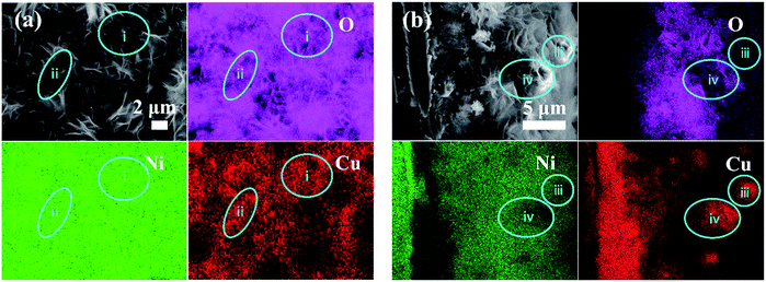 | ||
| Fig. 2 EDS mappings of the Ni(OH)2–Cu film on NF: (a) top view and (b) cross sectional view (taken from the knife-scratched sample surface). Blue circles are used to mark some Cu-rich regions. | ||
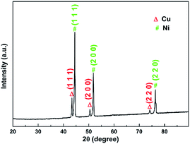
Fig. 3 displays the XRD pattern of the as-synthesized sample. Strong peaks belonging to metallic Ni (JCPDS 70-1849) and Cu (JCPDS 89-2838) can be seen from the graph. Ni peaks come from the NF substrate and Cu peaks suggest the formation of metallic copper during the hybrid film synthesis. The existence of metallic Cu explains why copper appears in oxygen deficient regions shown in Fig. 2. The signal of nickel hydroxide in this plot is very weak due to the very strong Cu and Ni signals.
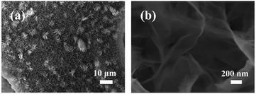
Fig. 4 shows the flaked morphology of the hybrid film in low and high magnification SEM images. A good coverage on the NF substrate by the as-fabricated nanosheets can be seen from Fig. 4(a). As exhibited in Fig. 4(b), the outer hybrid film is mainly comprised of geometrically sheet-like 2D structures with thickness at a nanoscale level. As the charge storage mechanism of pseudocapacitor is mainly based on the surface/near-surface reaction, this morphology of porous ultrathin nanosheets is among the most favorable architectures for SC electrode materials owing to the large surface area and high exposure to electrolyte ions.
The Ni(OH)2 phase in the sample is evidenced from Fig. 5. From Fig. 5(a), the magnified XRD pattern of Fig. 3, (101) and (110) peaks of Ni(OH)2·0.75H2O (JCPDS 38-0715) are observed. Since these peaks are very weak, TEM and SAED are further employed to examine the phases of the nanosheets. As exhibited in Fig. 5(b), the as-formed nanosheets show a foldaway silk-like morphology with high electron transparency, indicating an ultrathin nature,3 which is consistent with the SEM observation. The SAED pattern of the nanosheets is shown in Fig. 5(c). The d-spacings derived from these symmetric ring/spots reveal that two sets of rings exist in the SAED pattern. One set can be indexed to Ni(OH)2·0.75H2O (JCPDS 38-0715) crystal planes of (101), (015), (110) and (113), and the other set to Cu (JCPDS 89-2838) crystal planes of (111), (220) and (311). Such results suggest the outer nanosheet phases of the sample to be Ni(OH)2·0.75H2O and metallic Cu. The ratio of these two phases in the upper nanosheet layers are measured by XPS (see Fig. S1 and ESI†). The atomic ratio of Ni to Cu element is 11.58: 0.68 ≈ 17.03. The corresponding weight ratio of the Ni(OH)2 phase (Ni(OH)2·0.75H2O) to Cu phase is calculated to be 28.46.
 | ||
| Fig. 5 (a) XRD pattern of Ni(OH)2–Cu on a magnified scale; (b) TEM image and (c) SAED pattern of Ni(OH)2–Cu nanosheets scratched down from the substrate. | ||
3.2 Electrochemical properties of the Ni(OH)2–Cu hybrid electrode
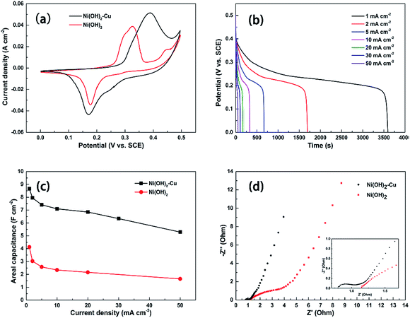
To explore the electrochemical properties of the as-synthesized electrode material, electrochemical tests in three-electrode configuration were performed. For comparison, we have also examined the pure Ni(OH)2 sample (SEM image is shown in Fig. S2†) prepared under the same experimental conditions but without adding the copper source. The morphologies of the Ni(OH)2–Cu sample and the pure Ni(OH)2 sample are quite similar, although the Ni(OH)2–Cu sample appears slightly more porous. As seen in Fig. 6(a), the typical cyclic voltammetry (CV) curve of the Ni(OH)2–Cu hybrid exhibits a pair of well-defined redox peaks, indicating a strong pseudocapacitive behavior of the hybrid material.4 The redox reaction corresponds to the reversible conversion between Ni(II) and Ni(III):| Ni(OH)2 + OH− ↔ NiOOH + H2O + e− | (3) |
Compared to the pure Ni(OH)2 electrode, the CV curve of the Ni(OH)2–Cu electrode shows an evidently larger area, and the specific capacitances of the two electrodes are calculated to be 3.2 F cm−2 and 5.95 F cm−2 accordingly. The prominent enhancement in areal capacitance of Ni(OH)2–Cu compared with Ni(OH)2 appears to be mainly attributed to the interwoven structure of metallic Cu and Ni(OH)2 nanosheets. The metallic Cu layer formed at the bottom of the hybrid film on NF provides a high conducting path and low contact resistance for charge carriers. More importantly, the upper interwoven metallic copper in the film provides a highly-conductive network that enables fast transportation of charge carriers within the electrode and benefits fast redox reaction kinetics of the active material.
Fig. 6(b) plots a series of discharging curves of the Ni(OH)2–Cu electrode tested at increasing current densities. The expected non-linear shapes of the discharge curves confirm the pseudocapacitive nature of the electrode. The corresponding areal capacitances (shown in Fig. 6(c)) are calculated from the discharging curves based on eqn (4):
 | (4) |
To further understand the enhanced electron transportation capability of the Ni(OH)2–Cu electrode, EIS analysis is performed on the Ni(OH)2–Cu sample and Ni(OH)2 reference (Fig. 6(d)). At very high frequencies, the intercept at the real axis (Z′) represents a combinational resistance of intrinsic resistance of the electrode material, contact resistance at the active material/current collector interface and ionic resistance of the electrolyte.21 The Ni(OH)2–Cu sample exhibits a much smaller real axis intersection than Ni(OH)2, indicating its significantly smaller internal resistance. The Ni(OH)2–Cu electrode exhibits a much smaller depressed semicircle, which represents reduced charge-transfer resistance occurring in faradic reactions at the electrode–electrolyte interface. These results demonstrate that the Cu network in the active material helps to provide a favorable electron-transport pathway and improve the conductivity of the sample. In the low frequency area, the slope of the curve shows the Warburg impedance that is related to the electrolyte diffusion in a porous electrode and proton diffusion in host materials.22 As shown in the graph, the Ni(OH)2–Cu electrode displays a more ideal straight line along the imaginary axis, indicating a lower diffusion resistance occurring in this electrode.
The specific areal capacitance of this sample is also compared with other Cu–Ni compound based electrodes reported in the literature in Table 1. The areal capacitances are calculated based on the mass loading and gravimetric capacitances provided in those papers. It can be seen that our Ni(OH)2–Cu hybrid shows enormously enhanced capacitance, which is possibly due to its advanced structure.
| No. | Material | Current density (mA cm−2) | Areal capacitance (F cm−2) | References |
|---|---|---|---|---|
| 1 | NiCu(OH)2CO3 nanowire on Cu foam | 2.2 | 2.14 | 24 |
| 2 | Ternary Ni–Cu–OH on the carbon nanofiber substrate | 6 | 0.77 | 25 |
| 3 | Nickel copper hydroxide (NCH) on the carbon fiber paper | 2 | 2.88 | 26 |
| 4 | Cu0.2Ni0.8O on Cu foam | 5 | 2.97 | 27 |
| 5 | Nickel copper oxide (NCO) nanowires on NF | 2.5 | 2.24 | 28 |
| 6 | Ni(OH) 2 –Cu hybrid on NF | 2 | 7.95 | Current work |
| 5 | 7.41 | |||
| 10 | 7.1 |
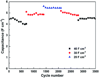
The cycling performance of the Ni(OH)2–Cu electrode was evaluated by charge/discharge testing at a series of high current densities. As observed from Fig. 7, a slight increase in areal capacitance from 4.44 F cm−2 to 4.54 F cm−2 occurs during the first 160 cycles at 40 mA cm−2, which corresponds to full activation of the electrode material as mentioned in several reports.5,23 Then the capacitance goes through a slight decrease in each of the first three sections (700 cycles for each section) tested at reduced current densities, where a tendency shows up that smaller charging/discharging rate results in higher capacitance retention during the cycling test (90.5%, 95.3% and 97.1% retention after 700 cycles at 40, 30 and 20 mA cm−2, respectively). Ultimately, the Ni(OH)2–Cu electrode exhibits a capacitance of 4.47 F cm−2 (at 40 mA cm−2) after 3500 cycles, corresponding to 98.5% retention of the highest capacitance achieved at 40 mA cm−2, indicating an outstanding cycling stability.
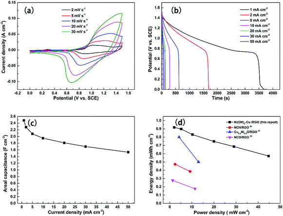
To further evaluate the Ni(OH)2–Cu electrode for real applications, the performance of the two-electrode asymmetric supercapacitor, with Ni(OH)2–Cu as the positive electrode and RGO as the negative electrode, was tested. Fig. 8(a) shows typical CV curves of the ASC tested in a 2 M KOH electrolyte at various scan rates between 0 and 1.5 V. The clearly observed redox peaks indicate the pseudocapacitance contribution from the positive electrode.29,30 The galvanostatic discharge curves acquired at different current densities are exhibited in Fig. 8(b). The nonlinearities of these discharge curves further confirm that the faradaic reaction occurred in the ASC. The specific areal capacitances of the ASC vs. various current densities were conducted and the corresponding results are shown in Fig. 8(c). A high areal capacitance of 2.48 F cm−2 is achieved at the small current density of 1 mA cm−1, while the capacitance retains 73% (1.81 F cm−2) and 61.7% (1.53 F cm−2) of the value at high current densities of 20 mA cm−2 and 50 mA cm−2, respectively. The results indicate a good performance of the ASC in both high specific capacitance and superior rate capability, which is mostly attributed to the advanced architecture of the positive electrode.
Energy density and power density are two important parameters for characterizing the electrochemical performance of a supercapacitor. Based on the discharge curves, the areal energy density and power density can be calculated using the following equations:
 | (5) |
 | (6) |
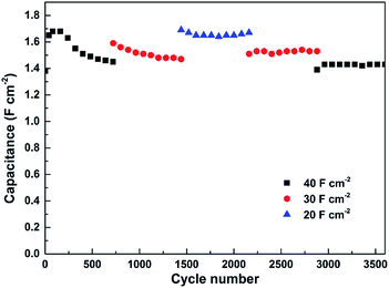
The cycling stability of the as-fabricated ASC was evaluated by performing 3600 cycles of the charge/discharge test at various current densities (see Fig. 9). An activation process of the electrode first takes place during the initial 80 cycles at 40 mA cm−2 and the capacitance goes through an increase from 1.38 F cm−2 to 1.68 F cm−2. Then the capacitance suffers a minor decrease in each of the first two 720 cycles tested at 40 and 30 mA cm−2, respectively. In the last three 720 cycles of testing, however, the capacitance of the ASC remains stable with no sign of further decrease. In the end, a capacitance of 1.43 F cm−2 (85.1% of the highest capacitance achieved at 40 mA cm−2) is retained by the ASC after 3600 cycles, confirming its good cycling stability.
4. Conclusion
In summary, the Ni(OH)2–Cu hybrid electrode was synthesized through a facile and green one-step hydrothermal process. Only two metal salts and water were used as precursors without the need of adding alkali, oxidant or organic solutions. The as-fabricated electrode possesses an advanced architecture with the Cu nanoparticle layer at the bottom upon which grows an interwoven nanosheet layer of Ni(OH)2 and Cu. Such a Ni(OH)2–Cu hybrid electrode delivers an ultra-high areal capacitance of 8.66 F cm−2 at 1 mA cm−2, superior rate performance such that the capacitance of 6.85 and 5.29 F cm−2 is retained when the current density goes up to 20 and 50 mA cm−2, corresponding to 79.1% and 61.8% retention, respectively, and also outstanding cycling stability. Moreover, the as-obtained Ni(OH)2–Cu//RGO ASC also exhibits high capacitive performance and superior energy densities especially at high power density. Therefore, the as-synthesized interwoven architecture of the Ni(OH)2–Cu hybrid shows great potential in high-performance supercapacitor applications.Acknowledgements
The support of Singapore Ministry of Education Academic Research Fund Tier 2 MOE Tier 2 MOE2013-T2-2-138, grant R-284-000-125-112 is appreciated.References
- J. Yan, Q. Wang, T. Wei and Z. Fan, Adv. Energy Mater., 2014, 4, 1300816 CrossRef.
- Y. Wang and Y. Xia, Adv. Mater., 2013, 25, 5336–5342 CrossRef CAS PubMed.
- C. Yuan, J. Li, L. Hou, X. Zhang, L. Shen and X. W. D. Lou, Adv. Funct. Mater., 2012, 22, 4592–4597 CrossRef CAS.
- H. Chen, L. Hu, M. Chen, Y. Yan and L. Wu, Adv. Funct. Mater., 2014, 24, 934–942 CrossRef CAS.
- J. Kang, A. Hirata, H. J. Qiu, L. Chen, X. Ge, T. Fujita and M. Chen, Adv. Mater., 2014, 26, 269–272 CrossRef CAS PubMed.
- X. A. Chen, X. Chen, F. Zhang, Z. Yang and S. Huang, J. Power Sources, 2013, 243, 555–561 CrossRef CAS.
- D. P. Dubal, G. S. Gund, C. D. Lokhande and R. Holze, ACS Appl. Mater. Interfaces, 2013, 5, 2446–2454 CAS.
- S. Min, C. Zhao, G. Chen and X. Qian, Electrochim. Acta, 2014, 115, 155–164 CrossRef CAS.
- J. Xu, S. L. Gai, F. He, N. Niu, P. Gao, Y. J. Chen and P. P. Yang, J. Mater. Chem. A, 2014, 2, 1022–1031 CAS.
- L. L. Zhang, Z. Xiong and X. S. Zhao, J. Power Sources, 2013, 222, 326–332 CrossRef CAS.
- X. H. Xia, D. L. Chao, Z. X. Fan, C. Guan, X. H. Cao, H. Zhang and H. J. Fan, Nano Lett., 2014, 14, 1651–1658 CrossRef CAS PubMed.
- W. C. Jiang, D. S. Yu, Q. Zhang, K. L. Goh, L. Wei, Y. L. Yong, R. R. Jiang, J. Wei and Y. Chen, Adv. Funct. Mater., 2015, 25, 1063–1073 CrossRef CAS.
- J. Zhu, Z. Xu and B. N. Lu, Nano Energy, 2014, 7, 114–123 CrossRef CAS.
- Z. G. Zeng, H. J. Zhou, X. Long, E. J. Guo and X. H. Wang, J. Alloys Compd., 2015, 632, 376–385 CrossRef CAS.
- Y. H. Li, Z. Y. Wang and Y. F. Zhang, J. Alloys Compd., 2015, 644, 47–53 CrossRef CAS.
- H. Xia, C. Y. Hong, X. Q. Shi, B. Li, G. L. Yuan, Q. F. Yao and J. P. Xie, J. Mater. Chem. A, 2015, 3, 1216–1221 CAS.
- Z. Tang, C. H. Tang and H. Gong, Adv. Funct. Mater., 2012, 22, 1272–1278 CrossRef CAS.
- J. Li, W. Zhao, F. Huang, A. Manivannan and N. Wu, Nanoscale, 2011, 3, 5103–5109 RSC.
- Y. X. Xu, X. Q. Huang, Z. Y. Lin, X. Zhong, Y. Huang and X. F. Duan, Nano Res., 2013, 6, 65–76 CrossRef CAS.
- M. M. Wang, W. L. Ma, J. Y. Xue, F. M. Zhang and H. T. Cui, Phys. Status Solidi A, 2016, 213, 215–220 CrossRef CAS.
- X. Chen, C. Long, C. Lin, T. Wei, J. Yan, L. Jiang and Z. Fan, Electrochim. Acta, 2014, 137, 352–358 CrossRef CAS.
- L. Mei, T. Yang, C. Xu, M. Zhang, L. B. Chen, Q. H. Li and T. H. Wang, Nano Energy, 2014, 3, 36–45 CrossRef CAS.
- X. H. Xiong, D. Ding, D. C. Chen, G. Waller, Y. F. Bu, Z. X. Wang and M. L. Liu, Nano Energy, 2015, 11, 154–161 CrossRef CAS.
- X. Zheng, Y. Ye, Q. Yang, B. Geng and X. Zhang, Chem. Eng. J., 2016, 290, 353–360 CrossRef CAS.
- N. A. Alhebshi and H. N. Alshareef, Mater. Renew. Sustain. Energy, 2015, 4, 9 CrossRef.
- L. Zhang and H. Gong, Sci. Rep., 2015, 5, 18108 CrossRef CAS PubMed.
- L. Y. Zhang and H. Gong, ACS Appl. Mater. Interfaces, 2015, 7, 15277–15284 CAS.
- L. Zhang, C. Tang and H. Gong, Nanoscale, 2014, 6, 12981–12989 RSC.
- C. D. Wang, J. L. Xu, M. F. Yuen, J. Zhang, Y. Y. Li, X. F. Chen and W. J. Zhang, Adv. Funct. Mater., 2014, 24, 6372–6380 CrossRef CAS.
- A. Pendashteh, S. E. Moosavifard, M. S. Rahmanifar, Y. Wang, M. F. El-Kady, R. B. Kaner and M. F. Mousavi, Chem. Mater., 2015, 27, 3919–3926 CrossRef CAS.
Footnote |
| † Electronic supplementary information (ESI) available. See DOI: 10.1039/c6ta03336a |
| This journal is © The Royal Society of Chemistry 2016 |

