
 Open Access Article
 This Open Access Article is licensed under a
 Creative Commons Attribution 3.0 Unported Licence
Low-energy formate production from CO2 electroreduction using electrodeposited tin on GDE†
E.
Irtem
a,
T.
Andreu
 *ab,
A.
Parra
a,
M. D.
Hernández-Alonso
c,
S.
García-Rodríguez
c,
J. M.
Riesco-García
c,
G.
Penelas-Pérez
c and
J. R.
Morante
ab
*ab,
A.
Parra
a,
M. D.
Hernández-Alonso
c,
S.
García-Rodríguez
c,
J. M.
Riesco-García
c,
G.
Penelas-Pérez
c and
J. R.
Morante
ab
aDepartment of Advanced Materials for Energy, Catalonia Institute for Energy Research (IREC), Jardins de les Dones de Negre, 1, 08930 Sant Adrià de Besòs, Catalonia, Spain. E-mail: tandreu@irec.cat
bUniversitat de Barcelona (UB), Martí i Franquès, 1, 08028 Barcelona, Catalonia, Spain
cRepsol Technology Center, C/ Agustin de Betancourt s/n, 28935 Móstoles, Madrid, Spain
First published on 4th August 2016
Abstract
Tin electrodeposition on carbon fibers have been implemented for gas diffusion electrodes for the electroreduction of CO2 to formate in a electrochemical flow cell design. Unlike other approaches, this method does not incorporate any additive or binder in the electrode, thus improving their catalytic performances. Once optimized, the system shows an improved dependence of the effective production of formate yield by surface and time units, mol m−2 s−1, on the consumed energy by mol, W h mol−1. It reduces the formic acid production energy cost, requiring less than 250 W h mol−1, with formate faradaic efficiency as high as 71% and is fully stable for at least 6 hours.
1. Introduction
In order to move towards a circular economy, which implies reducing waste to a minimum, overturning the concept of CO2 as a pollutant, instead exploring its value as a feedstock through CO2 reduction techniques, emerges as an interesting opportunity. In this context, the electroreduction of CO2 (CO2R) in aqueous media is particularly interesting, and feasible, as water-based electrolytes can be used as a proton source, and the reaction is conducted at room temperature.1 For that, on one hand, it is important to promote CO2R over the competing hydrogen evolution reaction (HER) to guarantee the efficient production of reduced CO2 products. Furthermore, at least CO and HCOOH can compete as reduction compounds among CO2R:2| 2H+ + 2e− ⇔ H2, E0 = 0.00 VRHE | (1) |
| CO2 + 2H+ + 2e− ⇔ CO + H2O, E0 = −0.103 VRHE | (2) |
| CO2 + 2H+ + e− ⇔ HCOOH, E0 = −0.225 VRHE | (3) |
In order to favor the formic acid production, the difference among energy barriers needs to be compensated using a catalyst that favors the formation of formic acid over the other products. Many researchers have reported results of CO2R into formate (HCOO−) on different metal catalysts such as Sn, Pb, Bi and In.3–8 The cause of their selectivity to formate were related to the large overpotential for hydrogen evolution, giving enough room for the stabilization of intermediate steps for formate production, i.e. by formation of free or weakly adsorbed CO2˙− followed by proton attack to the carbon atom.9 Among these catalyst candidates, Sn appears to be the most abundant and environmentally friendly.
Furthermore, the low CO2 solubility (0.034 M) in aqueous solution is also an important issue. Therefore, a gas diffusion electrode (GDE) with disperse catalyst material is desirable in order to minimize the mass transport limitations and improve the availability of the three phase interfaces (TPI), which is the meeting point of CO2 gas–liquid electrolyte–electrode, where the catalyst reaction will take place.
Among the different potential CO2 reduced sub-products, formate, or formic acid, has been receiving great industrial attention because of its versatility in various applications (e.g., direct formic acid fuel cells,10 leather, textile, chemical and food industries). Likewise, its production from CO2 electrochemical reduction appears as a powerful alternative as long as the energy consumption is kept low enough during the electrosynthesis as well as in the posterior concentration procedure to reach the background purity of commercial formic, typically 85% in weight.11 This parameter is especially relevant for ensuring the economic viability of the process. Moreover, in order to decrease investment costs, the use of inexpensive electrode materials with high degradation endurance is also required. The price of the formic acid metric ton is currently around 1000€ with an estimated annual increase of about 2%. In this scenario, according to the existing literature12–15 nowadays, high faradaic efficiency values are obtained with energy consumptions per mol higher than 300 W h, whereas the combustion energy under standard conditions associated to formic acid is −254.6 kJ mol−1 (70.7 W h mol−1).
Recent efforts have been paid on the implementation of GDE for CO2R. In this way, a high density of active sites should be available in a three-dimensional network of conductive supporting materials, allowing simultaneously CO2 gas diffusion and charge transfer. Typically, a catalyst layer, consisting of Sn nanopowders and/or SnO2 film with Nafion® solution and propanol to disperse the components (with carbon black, carbon nanotubes or graphene), is drop cast on a glassy carbon (GC) electrode or sprayed on a gas diffusion layer. These have received attention due to an enhanced efficiency caused by the use of nanosized electrocatalysts, obtaining results of faradaic efficiency for formate ranging between 65 and 73%, although the consumed energy per mol is not yet improved enough4,14–24 (a summary is given in Table S1†). Consequently, important efforts are still needed for simultaneously improving degradation endurance, maintaining high faradaic efficiencies for formate concentration and decreasing the required energy consumption for formic acid synthesis. All these conditions must be fulfilled to satisfy the minimum requirements for its industrial applicability. Beyond these aspects, only a few studies in the literature have been addressed toward the influence of the gas and electrolyte flow rates on the production yield in an up-scalable and continuous flow cell using GDE25,26 considering the final concentration of the product in the catholyte.
In this work, a CO2 gas diffusion electrode based on submicron Sn catalyst particles, obtained by electrodeposition onto the carbon fibers of the GDE, was used as a cathode to convert CO2 into formate (HCOO−) with a high CO2R faradaic efficiency that achieves around 85%, of which 71% corresponds to sodium formate. In contrast to previous studies, no additive, such as a conductive powder or additional binder in the gas diffusion electrode that extend the foreseen life time, was used, thus increasing degradation endurance. This electrode has been used as an improved cathode in a stacked flow cell system that combines a well-defined electrode–electrolyte (membrane)–electrode interface, working close to each other to increase the diffusion of ions and decrease the cell resistance. At the same time, based on the continuous system, the gas/liquid flow ratio can be adequately modified to optimize formate production. Unlike previously proposed approaches,4,13–16,26–28 this system and procedure has a lower energy consumption per mol, (<250 W h mol−1), for competitive formate effective production yields, in the range 2–4 × 10⁻⁴ mol m−2 s−1.
2. Experimental
2.1. Catalyst preparation and characterization
Tin catalysts (Sn-GDE) were obtained by electrodeposition on carbon fibers using a conventional three electrode cell configuration. A sheet of carbon paper (Toray® carbon paper, TGP-H-60) with a size of 30 × 34 mm was used as a catalyst support (working electrode), the counter electrode was 40 × 40 mm graphite foil (0.5 mm thick, 99.8%, Alfa Aesar) and Ag/AgCl/KCl (3M) (E0 = 0.203 VNHE) was used as a reference electrode. A pyrophosphate bath containing 0.40 M K4P2O7, 0.09 M Sn2P2O7 and 0.05 M C4H6O6 was used as the electrolyte for tin electrodeposition.29 To enhance mass transport and prevent side reactions, such as the oxygen reduction reaction, argon gas was continuously bubbled during the plating process. The electrodeposition was carried out using a Biologic SP-150 potentiostat working under galvanostatic mode, applying a current density of 15 mA cm−2 during 5 min at room temperature. After electrodeposition, each electrode was thoroughly rinsed with deionized water and dried in a vacuum oven (25 torr, Ar atmosphere) at 70 °C for 2 h.Structural characterization was carried out by X-ray diffraction (XRD) in a D8 Advance Bruker equipment with a Cu Kα1 radiation source working at 40 kV and 40 mA with the samples being scanned from 2θ = 10° to 80° at a rate of 0.02 s−1 in Bragg–Brentano geometry. Morphology of the as deposited Sn-GDE was observed using a Zeiss (Auriga) scanning electron microscope (SEM) and elemental analysis was performed by the same microscope equipped with an Oxford X-ray energy dispersive spectrometer (EDS).
2.2. Electrolysis cell and experimental set-up
Carbon dioxide electroreduction experiments were carried out in a filter-press type electrochemical cell (Micro Flow Cell, Electrocell A/S), where a Dimensionally Stable Anode plate (DSA/O2, Electrocell S/A) was used as the anode and Sn-GDE was used as the cathode. An ionic transport membrane (Nafion® 117) divided the cell into two separated anodic and cathodic compartments. A leak-free Ag/AgCl 3.4 M KCl reference electrode (Warner Instruments) was assembled in a polytetrafluoroethylene (PTFE) frame of the cell and placed very close to the cathode surface. As seen in Fig. 1, the cell had three inputs (catholyte, anolyte and CO2) and two outputs (catholyte + CO2 and anolyte). Anolyte (0.5 M NaOH, Panreac, >98%) and catholyte (0.5 M NaHCO3, Merck >99.9%, pre-electrolyzed at −2 V under nitrogen bubbling to remove metal impurities) were kept in two separated tanks and recirculated continuously into the cell by a dual peristaltic pump (Major Science, MU-D02) to accumulate liquid products. A mass flow controller (Bronkhorst F-201CV) was used to control the CO2 flow rate entering the system, measured downstream by a volumetric digital flowmeter (Agilent ADM 2000). The flow of CO2 gas and electrolytes were kept at 10 mL min−1 unless otherwise specified, gas-to-liquid (G/L) ratio = 1. The experiments were carried out under potentiostatic conditions in a two-electrode configuration, applying a voltage between anode and cathode, using a potentiostat/galvanostat Biologic VMP3. A second potentiostat/galvanostat Biologic VMP3 was used to monitor the three-electrode configuration and the voltage of each electrode versus the Ag/AgCl reference electrode. For the sake of clarity, the potential was transformed to the reversible hydrogen electrode (RHE) scale: E (VRHE) = E (VAg/AgCl) + 0.0592 pH + 0.203.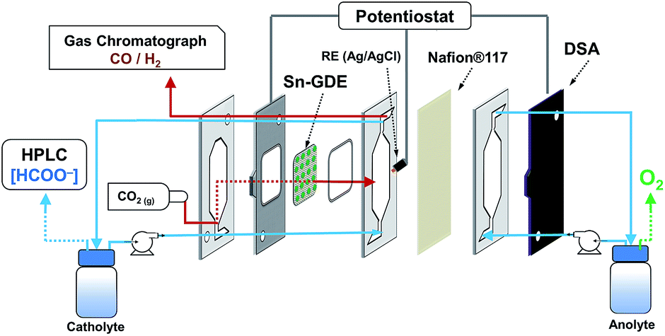 | ||
| Fig. 1 Scheme of the electrochemical flow cell. | ||
The faradaic efficiency to formate is the percentage of the total charge supplied that was used to produce formate. For its quantification, a total charge of 4 C mL−1 of catholyte (typical 50 mL) was employed for the electrolysis to assure a measurable quantity of formate at every potential. The product in the liquid phase was analyzed, after acidification, by a high performance liquid chromatography system (HPLC, Perkin Elmer Flexar SQ300MS) equipped with a Rezex ROA-Organic Acid H+ (8%) column (300 × 7.8 mm, Phenomenex), an isocratic pump (2.5 mM H2SO4, 6 mL min−1) and a UV detector set at 210 nm. Analogously, carbon monoxide and hydrogen faradaic efficiencies were calculated using the analysis of the outlet gas by gas chromatography using a multichannel Agilent 490 microGC equipped with two Molsieve columns with argon carrier gas for hydrogen analysis and with helium carrier gas for carbon monoxide analysis.
3. Results and discussion
3.1. Tin catalyst immobilized by electrodeposition
Tin catalysts (Sn-GDE) were obtained by electrodeposition on carbon fibers using a pyrophosphate bath. One of the advantages of the pyrophosphate solution is that its pH is close to neutrality (pH = 8). Then, with tartaric acid additive as the complexing agent, deposits can be obtained with a uniform morphology by favoring Sn metal reduction over hydrogen evolution (HER). As seen in the cyclic voltammetry (Fig. 2), the reduction of Sn2+ to Sn on the carbon fiber electrode starts at −0.13 VRHE, close to its standard redox potential,2 while HER is significantly retarded. Cathodic scan of the cyclic voltammogram shows a plateau near 20 mA cm−2 because tin reduction reaches a limiting current density. Later, a significant hydrogen formation was detected from −1.32 VRHE.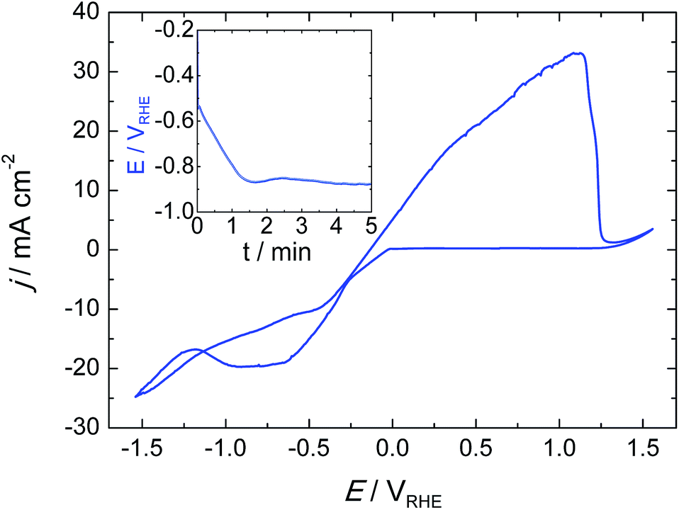 | ||
| Fig. 2 Cyclic voltammogram for tin deposition and stripping on the gas diffusion electrode (C-Toray TGP-H-60) in pyrophosphate bath (pH 8.3) at a scan rate of 20 mV s−1. Inset, chronopotentiometry at 15 mA cm−2 during Sn catalyst deposition. | ||
In order to understand the deposition mechanism, we applied five current values ranging from 1 to 30 mA cm−2. For all deposited samples, the charge density was kept constant (4.5 C cm−2), which gives rise to coverage of the carbon fibers located in the front part of the gas diffusion electrode. Depending on the current density used, the nucleation and distribution of the layer deposited onto the carbon fibers changes as well as the depth of the achieved coverage. Due to the nucleation, growth and deposition rates, the procedure from 1 to 6 mA cm−2 did not uniformly cover the fibers (Fig. S1†); while a current density that exceeds the limiting current density, like 30 mA cm−2, gave rise to Sn particles forming needle-like deposits with poor mechanical adherence due to concomitant hydrogen evolution. These deposits peeled off under a stream of N2 gas and also when the electrode is dipped inside a solution. In the range from 10 to 30 mA cm−2, 15 mA cm−2 was estimated to be the optimal current density for a uniform and compact distribution of tin over the carbon fibers (Fig. 3a). The chronopotentiometric curve (inset in Fig. 1) acquired during electrodeposition at 15 mA cm−2 shows a sharp decrease of electrode potential due to charging of the double layer since it has reached the potential where tin reduction takes place.
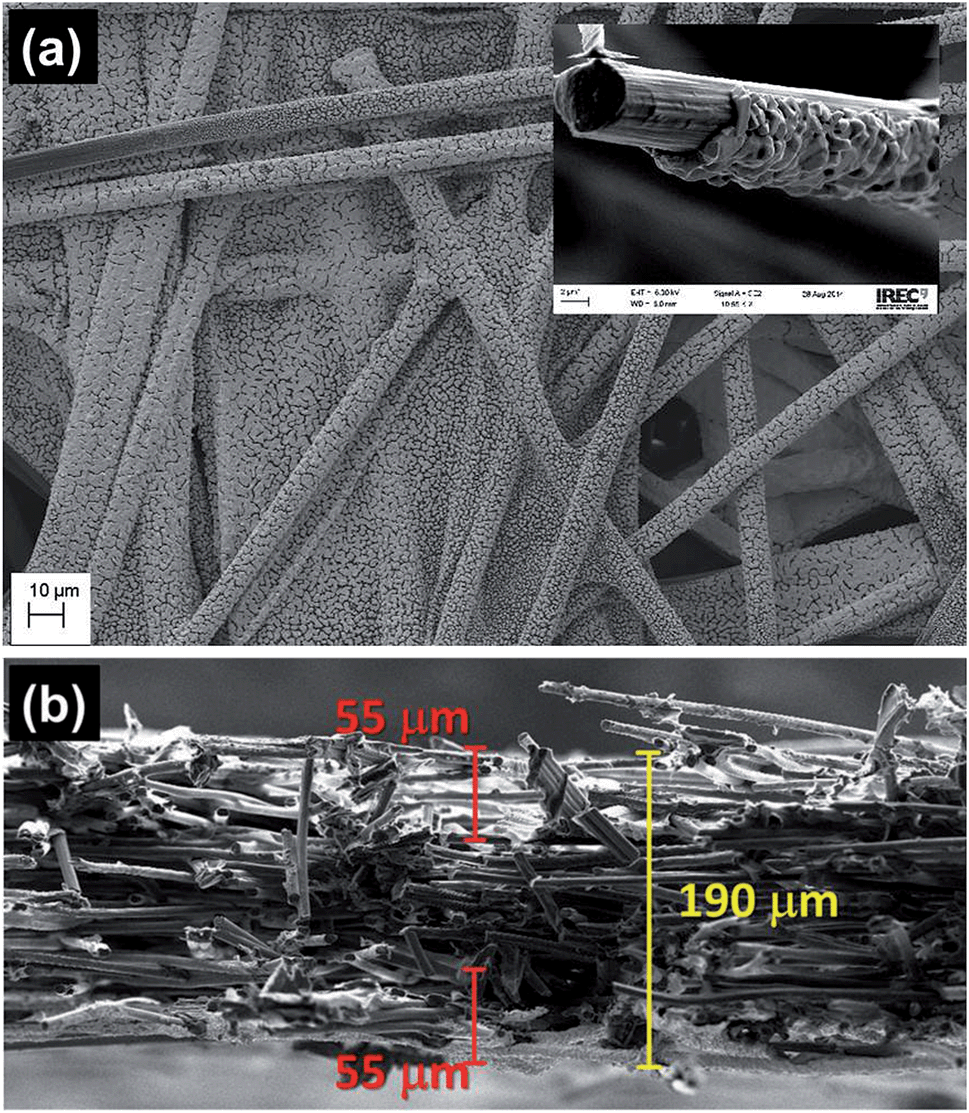 | ||
| Fig. 3 (a) FE-SEM top view image of the Sn-GDE electrode obtained by electrodeposition of Sn at 15 mA cm−2 for 4.5 C cm−2 on C-Toray paper from pyrophosphate solution. Inset shows the Sn deposit on a carbon fiber. (b) FE-SEM cross-section of Sn-GDE. | ||
Under these conditions, a thickness around 1 μm around a single carbon fiber was confirmed by FE-SEM. When the deposition was carried out at 15 mA cm−2, the average Sn loading on GDE, measured by weight difference, was 2.6 mg cm−2 for 4.5 C cm−2, and consequently, the average faradaic efficiency of Sn electrodeposition was 94%. Fig. 3b shows the cross-section of the sample, confirming Sn film formation at 50 ± 5 μm inside the porous electrode at both sides of the carbon paper.
The XRD pattern (Fig. S2†) shows that, among its allotropes, the catalyst obtained by electrodeposition crystallizes in its beta phase with a tetragonal structure. Besides the graphite reflection from the C-Toray® paper substrate, the (200) and (101) peaks of β-Sn were the strongest signals observed for the polycrystalline film and all the other peaks correspond well with the reference pattern.
3.2. Gas diffusion electrode test
Fig. 4 presents the comparison of polarization curves of the electroreduction on a glassy carbon (GC) electrode, pristine gas diffusion electrode (GDE), and electrodeposited Sn on GDE (Sn-GDE) in 0.5 M NaHCO3 electrolyte buffer under Ar or CO2 bubbling. The lower current density achieved with GC, compared to that obtained with GDE, verifies the large active surface area of the porous electrode vs. a planar support. Besides this, the nearly two times higher current density of Sn-GDE under CO2 than under Ar (grey and red line, respectively) was attributable to the electroreduction of CO2. The standard potential of CO2 reduction to formate and carbon monoxide are −0.225 and −0.103 VRHE (ref. 30) according to reactions in eqn (2) and (3), respectively. Hence, the overpotential of CO2 reduction was only 400 and 490 mV for CO and HCOO−. Furthermore, in comparison to the Ar-saturated solution, the current density increased by 3 times in the presence of CO2 gas at an overpotential of only 0.8 V. Compared with recent results with a 5 nm size catalyst,24 our electrodeposited Sn catalyst on carbon fiber performed at 0.25 V, regardless of the up-scaling challenges at larger electrode dimensions (Fig. S3†).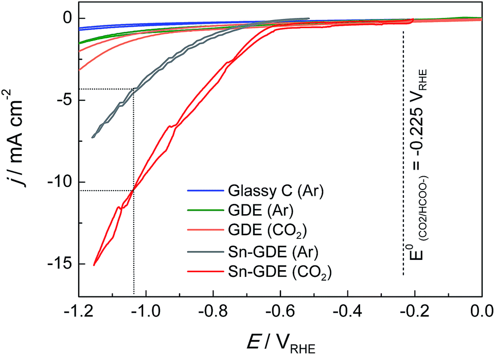 | ||
| Fig. 4 Cyclic voltammogram on glassy carbon (GC), GDE and Sn-GDE under 10 mL min−1 Ar or CO2 gas flow at a scan rate 20 mV s−1 in 0.5 M NaHCO3 electrolyte (GC electrode was tested in a 3-electrode EC cell with CO2 bubbling while the other electrodes were in filter-press EC cells). | ||
Before moving to the targeted electrolysis experiments, we conducted further analyses on the inertness of carbon fibers and final product contribution of the carbonate buffer. Firstly, previous studies showed31 that the carbon surface alone (GC and activated carbon) can reduce CO2 at sufficiently high potentials. Therefore, chronoamperometry tests were conducted with a similar flow cell to CO2R conditions during 10 hours onto pristine GDE under 10 mL min−1 CO2 gas flow at −0.85 VRHE in order to validate the inertness of GDE towards CO2 electroreduction. Secondly, Sn-GDE were tested under the same conditions, although the Ar gas flow was changed to 10 mL min−1 to confirm that CO2 in gas form was the true reactant involved in the electroreduction process at the TPI (gas–liquid–solid) sites and not only between liquid-electrode sites. At the end of the 10 hour experiments, 2 and 3 μmol h−1 of formate (HCOO−) were detected for GDE and Sn-GDE electrodes, respectively. Those values are equivalent to 24.8 and 36.6 ppm, which is within the error limit of HPLC protocols towards formate detection (<50 ppm). Therefore, the blank test results could be considered null in terms of formate faradaic efficiency, ensuring that gaseous CO2 was the active species.
3.3. CO2 reduction products and Tafel plot analysis
Total faradaic efficiencies towards formation of HCOO− and CO/H2 as liquid and gaseous products, respectively, are given in Fig. 5a. The working electrode potential versus CO2 conversion to formate frequently produces an “elbow” shape32 that was also observed in our results. As previously discussed by several authors,16,18–20,24,30,33,34 this is ascribed to a critical limiting step related to competitive hydrogen and carbon monoxide production. So, there is a (1![[thin space (1/6-em)]](https://www.rsc.org/images/entities/char_2009.gif) :1:1) product ratio voltage zone around −0.65 VRHE where Sn-GDE can convert CO2 into up to 32 ± 2.7% CO, as detected by an online gas chromatography set-up, 30 ± 2.8% HCOO− and the rest into H2. Increasing this voltage, the product ratio changes, favoring the production of HCOO− in the −0.65 to −1.1 VRHE range. Beyond that potential, selectivity shifts again towards H2 production. So by modulating the working conditions, a faradaic efficiency for HCOO−, detected by HPLC, as high as 71 ± 1.1% could be obtained, reaching 82 ± 2.0% of total CO2 reduced to C-products, including CO (6% ± 4.5%). Fig. S4† highlights the ratio control on the CO to H2 (syngas) with reliable stability for 2 hours for the voltages between −0.65 and −0.105 VRHE.
:1:1) product ratio voltage zone around −0.65 VRHE where Sn-GDE can convert CO2 into up to 32 ± 2.7% CO, as detected by an online gas chromatography set-up, 30 ± 2.8% HCOO− and the rest into H2. Increasing this voltage, the product ratio changes, favoring the production of HCOO− in the −0.65 to −1.1 VRHE range. Beyond that potential, selectivity shifts again towards H2 production. So by modulating the working conditions, a faradaic efficiency for HCOO−, detected by HPLC, as high as 71 ± 1.1% could be obtained, reaching 82 ± 2.0% of total CO2 reduced to C-products, including CO (6% ± 4.5%). Fig. S4† highlights the ratio control on the CO to H2 (syngas) with reliable stability for 2 hours for the voltages between −0.65 and −0.105 VRHE.
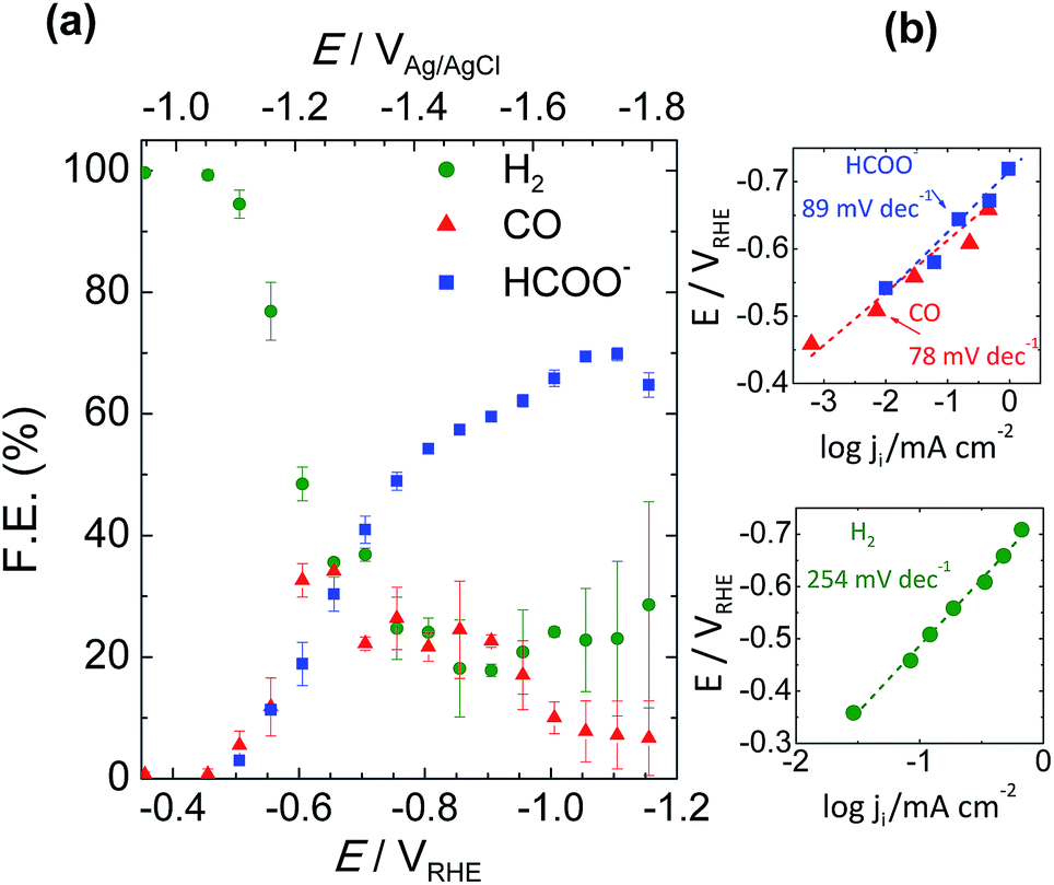 | ||
| Fig. 5 (a) Total faradaic efficiency of CO2 reduction products at the end of 200 C of charge passed from the external circuit and (b) the corresponding Tafel plots for production of HCOO−, CO and H2. | ||
Tafel slopes of the CO2 reduction process were calculated from analogous data obtained applying chronoamperometry tests of 200 C in 50 mL catholyte. Plotting the logarithm of partial current of each product against the electrode potential gives its Tafel slope value. Fig. 5b shows the reduction of CO2 to HCOO− and CO giving, respectively, a slope of 89 and 78 mV dec−1 at the low potential range. As expected, the Tafel slope value of H2 was found to be much higher, 254 mV dec−1, which was due to the low adsorption capability resulting in a higher overpotential and sluggish kinetics towards H2 evolution on Sn metal. Those findings are in good correlation with the Tafel values of Kanan et al.,17 which were 74 and 77 mV dec−1 for HCOO− and CO, respectively. Our initial findings, with comparable Tafel slopes and on-set voltage values,17,35,36 indicated a competing rate determining step prior to electron transfer to CO2 forming the CO2˙− radical.
3.4. Faradaic efficiency and hydrodynamic conditions
After verifying the catalytic performance of electrodeposited Sn on the carbon fiber-based gas diffusion electrode, the next step was to take advantage of the possibility of tuning the flow system, i.e., ratio of gas and liquid flows, and observe how mass transport can affect CO2 reduction. The influence of hydrodynamic conditions on mechanisms involved in the reaction intermediates has been well studied.37 These conditions may occur either because the electrode itself is in motion with respect to the solution, i.e. rotating disk electrode, or because there is a forced solution flow passing through a stationary electrode, i.e. channel electrodes or bubbling electrodes.38 The advantage is that a steady state is attained very quickly, meaning a diffusion layer would be formed at a certain distance from the electrode (diffusion layer, δ) by forced convection. In that state, the current can be related to flow rates by means of CO2 gas flux and the electrolyte that acts as the proton source. Therefore, changes in the formate production rate could take place by changing hydrodynamic conditions (gas and liquid flow rates) and electronic energies (applied potential or current) if some of these parameters were limiting these processes.Initially, a cyclic voltammetry test was conducted at different CO2 to Ar proportions, and the CO2 gas amount was increased from 0 to 100%. A clear distinction can be seen in the current density vs. potential plots in Fig. S5.† The increment of CO2 gas flow from 10 to 100% resulted in a one fold higher current density (0.69 to 8.3 mA cm−2) when the current generated under Ar was subtracted from CO2 to obtain partial current due to CO2 electroreduction, as shown in Fig. 6. Furthermore, when gas and liquid flow rates were equal (G/L = 1), the net current density reached 8.13 mA cm−2 for pure CO2 inlet at −1.1 VRHE. Further increases of gas flow rate above the liquid flow rate showed a smaller increase in the current density, 8.47 and 8.58 mA cm−2 – for G/L = 2 and 4 at 100 and 200 mL min−1 CO2 gas flow, respectively, while the liquid flow was 50 mL min−1. This result proved that not only the increase of the CO2 gas but also G/L flow ratio was essential to promote higher current densities. Here, the conversion of CO2 into formate (HCOO−) must be in relation to the liquid flow because the electrolyte was the critical component for the protonation of the intermediate species shown in eqn (3).
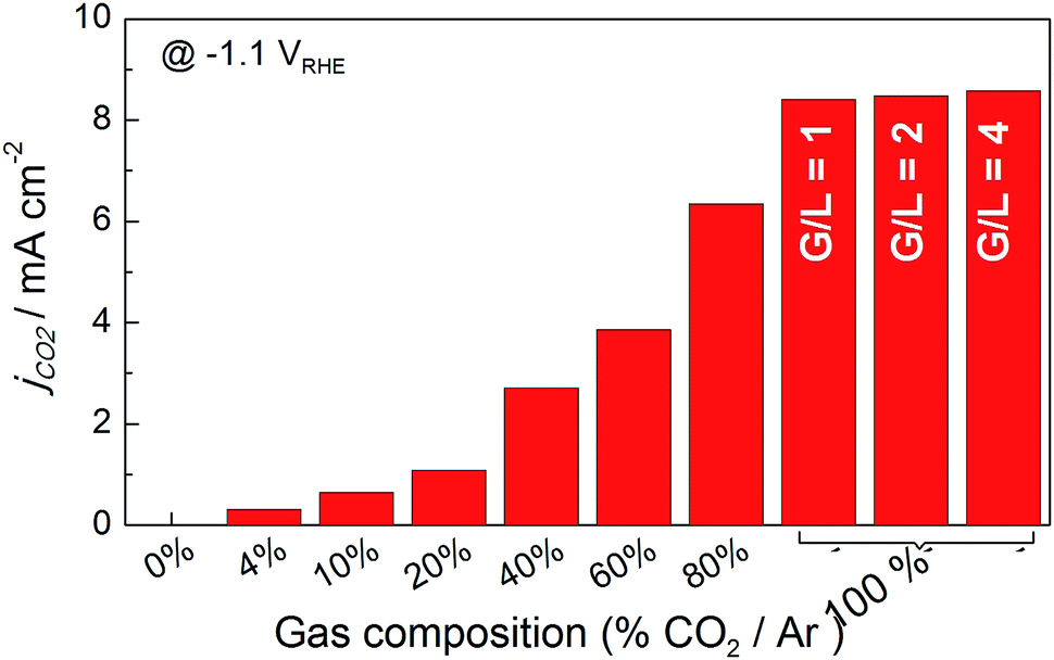 | ||
| Fig. 6 Histogram of net current density for CO2 reduction on Sn-GDE obtained by subtracting the current density value of Ar from CO2 at −1.1 VRHE in the CV scans (Fig. S5†). Data recorded in the filter-press cell in 0.5 M NaHCO3 (50 mL min−1) by increasing the amount of gas by CO2 percentage in Ar gas flow (total flow 50 mL min−1). For G/L 2 and 4, 100 and 200 mL min−1 of gas flow was used. | ||
For further understanding, electrolysis tests for 200 C were conducted at different cell currents (1, 5 and 10 mA cm−2) and G/L flow rates while individual electrode potential values were recorded during electrolysis. For the selected current densities, we explored 5 different G/L ratios by modifying the volumetric flow of CO2 gas and electrolyte from 5 to 50 mL min−1, resulting in G/L flow ratios of 0.5, 1, 2 and 5.
A thorough product analysis by liquid chromatography revealed a dependence of G/L ratio versus electrode potential, which is shown in Fig. 7a and b. All the lines show an arc-shaped dependence of formate efficiency to electrode potential. The most significant effect can be seen for the red and black curves, 0.2 and 0.5 G/L ratio. The amount of CO2 gas is not sufficient for reaching the overpotential required to convert CO2 into HCOO−. While a ratio of 1 provides higher current efficiency, the reaction was still under a rate control mechanism. Further increases of the G/L ratio gave a lower faradaic efficiency for formate in a related trend: 1 > 2 > 5. Here a remark should be given for the rising electrode potentials with the increment of G/L value in Fig. 7c. It is well-known that higher turbulence at the electrode–electrolyte interface hinders the complete utilization of the electrode surface. High amounts of bubbles most probably accumulate and locally block the active sites of the tin catalyst (Fig. 7d). Moreover, a contribution to the electrolyte resistance was revealed at the electrode interface, which is shown by the increase of the electrode potential in Fig. 7c.39
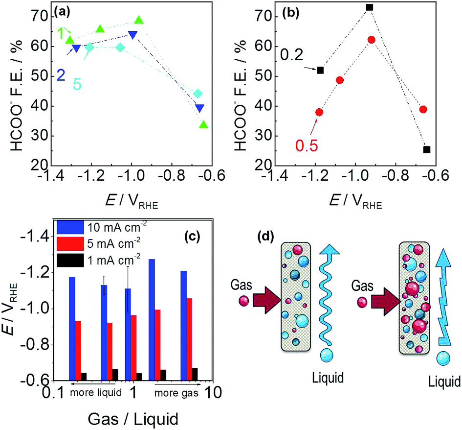 | ||
| Fig. 7 Faradaic efficiency of formate versus Sn-GDE electrode potential: (a) gas/liquid = 1, 2 or 5 and (b) gas/liquid = 0.2 or 0.5 in 0.5 M NaHCO3 for 200 C electrolysis. (c) CO2 gas to 0.5 M NaHCO3 electrolyte flow ratio effect on Sn-GDE electrode potential. (d) Schematic of gas and liquid flow over Sn-GDE, at G/L = 0.2 and 0.5 and G/L = 1, 2 and 5, left and right parts respectively. | ||
Moreover an improvement in faradaic efficiency was observed for 0.2 compared to 0.5. It seems that, at a low G/L flow ratio, where the liquid flow is superior to gas flow, there is sufficient time for the adsorption and stabilization of CO2(g) at the electrode surface before the consecutive step of electron uptake. Also, several (experimental and computational) studies highlighted that proton uptake of the CO2− radical could be a rate determining step and the faradaic efficiency for producing formate is promoted by proton existence at the surface layer and hydrogenating the carbon atom.20,33,35
3.5. Stability and cost of formate production
The catalytic activity of the Sn deposit was tested for 6 hours, results shown in Fig. S6(a),† where the dotted line corresponds to 100% faradaic efficiency of formate conversion from CO2. A stable formate production yield was attained (at 1 to 10 mA cm−2 applied current densities) during the whole experiment. Moreover, experiments at 1 and 5 mA cm−2 were held to longer times in order to maintain the analytical protocol by preventing a high product saturation altering the acidity of the electrolyte. The longstanding activity was attributed to the chosen deposition batch providing a catalyst coating free of impurities (proven by the EDX scan in Fig. S6†) and a well crystallized, compact catalyst film. Likewise, we have not observed any significant catalyst losses in weight. Previous works (Li & Oloman S1†) used Sn deposited on Cu mesh electrodes having 50–86% HCOOH conversion at a high expense of −4 to −5.8 V cell voltages but they reported low catalytic stability in their work (catalyst deteriorating after about 20 min operation) that was related to the loss of Sn from the mesh surface.40 In our case, it seems that there is no internal stress at the grain boundaries of the Sn deposit since no long crack formations have been observed.A final figure of merit to be highlighted is the energy efficiency of the process. Taking into account the combustion energy associated for formic acid (70.7 W h mol−1), a threshold of 250 W h mol−1 can be set, since the energy efficiency of the process would be 35%. In Fig. 8 the results of this work compared with previous literature that use a similar cell configuration but with a Sn-GDE obtained by spraying an ink (Sn nanoparticles + Nafion® solution) on C-Toray are shown.14,15 As can be seen, for the same applied current density, there are a wide range of values. Here, besides the current density, the faradaic efficiency of the process has a direct impact on the energy efficiency of the process, higher faradic efficiency implies a higher HCOO− rate and, consequently, lower energy consumption. Besides this, our binder free Sn-GDE electrode shows a lower resistance (1.2 Ω, see S3†) resulting in a lower iR drop, whereas reported values range from 5 to 7 Ω using ink-based electrodes (Wu, Jingjie, S1†).16 In our process, there was an optimum point in the range from 2 to 4 × 10⁻⁴ mol m−2 s−1 where the required energy can be lower than 200 W h mol−1 (whereas results from the bibliography show higher production yields up to 1 mmol m−2 s−1 but were associated to an energy consumption higher than 250 W h mol−1, which limits its practical application).
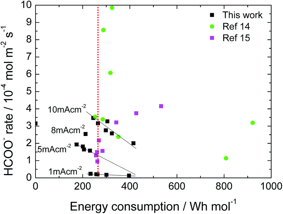 | ||
| Fig. 8 Energy consumption of CO2R to formate using Sn-GDE in a filter-press EC cell at different production rates. Data from this work and ref. 14 and 15. | ||
4. Conclusions
The electrodeposition of tin catalyst on carbon fibers, free of additives and up-scalable for gas diffusion electrodes, has been proved as a successful alternative methodology for preparing gas diffusion electrodes feasible for CO2 electroreduction to formate. The highest faradaic efficiency for HCOO− detected by HPLC was 71 ± 1.1%, being fully stable for at least 6 hours, reaching to 82 ± 2.0% of total CO2 conversion to C-products (HCOO− and CO). In the electrochemical flow cell, faradaic efficiencies were also dependent on the G/L flow ratio due to the turbulence promoted at the electrode by the CO2 flow. At low G/L flow ratios, the greater electrolyte flow provided higher faradaic efficiency (0.2 > 0.5), which could be due to the residence time of the CO2˙− intermediate species. As this process is high energy consuming, it is relevant to equilibrate its production yield with energy consumption. According to the reported data, by taking care of the electrocatalyst synthesis procedure onto the gas diffusion electrode, it is possible to decrease the energy consumption below 200 W h mol−1 while maintaining relatively high production yields by surface and time units, which converts the electroreduction method into a significant and competitive alternative for formate production from CO2 electroreduction.Acknowledgements
This work was supported by Repsol, S. A. Authors from IREC and UB belong to the M-2E (Electronic Materials for Energy, 2014SGR1638) Consolidated Research Group and the XaRMAE network of excellence on Materials for Energy of the “Generalitat de Catalunya”. IREC also acknowledges additional support by the European Regional Development Funds (ERDF, FEDER) and by MINECO projects ENE2012-3651 and MAT2014-59961-C2-1-R. EI thanks to AGAUR for his PhD grant (FI-2013-B-00769).Notes and references
- G. Centi, E. A. Quadrelli and S. Perathoner, Energy Environ. Sci., 2013, 6, 1711–1731 CAS.
- A. J. Bard, R. Parsons and J. Jordan, Standard potentials in aqueous solution, CRC press, 1985 Search PubMed.
- J. Medina-Ramos, R. C. Pupillo, T. P. Keane, J. L. DiMeglio and J. Rosenthal, J. Am. Chem. Soc., 2015, 137, 5021–5027 CrossRef CAS PubMed.
- Q. Wang, H. Dong and H. Yu, RSC Adv., 2014, 4, 59970–59976 RSC.
- C. W. Li, J. Ciston and M. W. Kanan, Nature, 2014, 508, 504–507 CrossRef CAS PubMed.
- K. P. Kuhl, T. Hatsukade, E. R. Cave, D. N. Abram, J. Kibsgaard and T. F. Jaramillo, J. Am. Chem. Soc., 2014, 136, 14107–14113 CrossRef CAS PubMed.
- B. Innocent, D. Pasquier, F. Ropital, F. Hahn, J. M. Léger and K. B. Kokoh, Appl. Catal., B, 2010, 94, 219–224 CrossRef CAS.
- Z. M. Detweiler, J. L. White, S. L. Bernasek and A. B. Bocarsly, Langmuir, 2014, 30, 7593–7600 CrossRef CAS PubMed.
- Y. Hori, H. Wakebe, T. Tsukamoto and O. Koga, Electrochim. Acta, 1994, 39, 1833–1839 CrossRef CAS.
- B. C. H. Steele and A. Heinzel, Nature, 2001, 414, 345–352 CrossRef CAS PubMed.
- A. P. G. Kieboom, Recl. Trav. Chim. Pays-Bas, 1988, 107, 685 CrossRef.
- G. K. S. Prakash, F. A. Viva and G. A. Olah, J. Power Sources, 2013, 223, 68–73 CrossRef CAS.
- M. N. Mahmood, D. Masheder and C. J. Harty, J. Appl. Electrochem., 1987, 17, 1159–1170 CrossRef CAS.
- A. Del Castillo, M. Alvarez-Guerra, J. Solla-Gullón, A. Sáez, V. Montiel and A. Irabien, Appl. Energy, 2015, 157, 165–173 CrossRef CAS.
- A. Del Castillo, M. Alvarez-Guerra and A. Irabien, AIChE J., 2014, 60, 3557–3564 CrossRef CAS.
- J. Wu, P. P. Sharma, B. H. Harris and X.-D. Zhou, J. Power Sources, 2014, 258, 189–194 CrossRef CAS.
- Y. Chen and M. W. Kanan, J. Am. Chem. Soc., 2012, 134, 1986–1989 CrossRef CAS PubMed.
- J. Wu, F. G. Risalvato, M. Shuguo and X.-D. Zhou, J. Mater. Chem. A, 2014, 2, 1647–1651 CAS.
- J. Wu, F. G. Risalvato, P. P. Sharma, P. J. Pellechia, F.-S. Ke and X.-D. Zhou, J. Electrochem. Soc., 2013, 160, F953–F957 CrossRef CAS.
- J. Wu, F. G. Risalvato, F.-S. Ke, P. J. Pellechia and X.-D. Zhou, J. Electrochem. Soc., 2012, 159, F353–F359 CrossRef CAS.
- S. Lee, J. D. Ocon, Y. I. Son and J. Lee, J. Phys. Chem. C, 2015, 119, 4884–4890 CAS.
- Y. Fu, Y. Liu, Y. Li, J. Qiao and X. D. Zhou, ECS Trans., 2015, 66, 53–59 CrossRef.
- C. Zhao, J. Wang and J. B. Goodenough, Electrochem. Commun., 2016, 65, 9–13 CrossRef CAS.
- S. Zhang, P. Kang and T. J. Meyer, J. Am. Chem. Soc., 2014, 136, 1734–1737 CrossRef CAS PubMed.
- Y. Hori, H. Konishi, T. Futamura, A. Murata, O. Koga, H. Sakurai and K. Oguma, Electrochim. Acta, 2005, 50, 5354–5369 CrossRef CAS.
- M. Alvarez-Guerra, A. Del Castillo and A. Irabien, Chem. Eng. Res. Des., 2014, 4, 692–701 CrossRef.
- M. Alvarez-Guerra, S. Quintanilla and A. Irabien, Chem. Eng. J., 2012, 207–208, 278–284 CrossRef CAS.
- Q. Wang, H. Dong and H. Yu, J. Power Sources, 2014, 271, 278–284 CrossRef CAS.
- M. Shafiei and A. T. Alpas, J. Power Sources, 2011, 196, 7771–7778 CrossRef CAS.
- B. P. Sullivan, K. Krist and H. Guard, Electrochemical and electrocatalytic reactions of carbon dioxide, Elsevier, 1992 Search PubMed.
- R. M. Hernández, J. Márquez, O. P. Márquez, M. Choy, C. Ovalles, J. J. Garcia and B. Scharifker, J. Electrochem. Soc., 1999, 146, 4131–4136 CrossRef.
- M. Jitaru, D. Lowy, M. Toma, B. Toma and L. Oniciu, J. Appl. Electrochem., 1997, 27, 875–889 CrossRef CAS.
- W. Lv, R. Zhang, P. Gao and L. Lei, J. Power Sources, 2014, 253, 276–281 CrossRef CAS.
- R. P. S. Chaplin and A. A. Wragg, J. Appl. Electrochem., 2003, 33, 1107–1123 CrossRef CAS.
- C. Cui, J. Han, X. Zhu, X. Liu, H. Wang, D. Mei and Q. Ge, J. Catal., 2016 DOI:10.1016/j.jcat.2015.12.001.
- C. Cui, H. Wang, X. Zhu, J. Han and Q. Ge, Sci. China: Chem., 2015, 58, 607–613 CrossRef CAS.
- J. Newman and K. E. Thomas-Alyea, Electrochemical systems, John Wiley & Sons, 2012 Search PubMed.
- A. J. Bard and L. R. Faulkner, Electrochemical methods: fundamentals and applications, Wiley, New York, 1980 Search PubMed.
- H.-R. M. Jhong, S. Ma and P. J. A. Kenis, Curr. Opin. Chem. Eng., 2013, 2, 191–199 CrossRef.
- H. Li and C. Oloman, J. Appl. Electrochem., 2005, 35, 955–965 CrossRef CAS.
Footnote |
| † Electronic supplementary information (ESI) available. See DOI: 10.1039/c6ta04432h |
| This journal is © The Royal Society of Chemistry 2016 |