 Open Access Article
Enhanced ideal strength of thermoelectric half-Heusler TiNiSn by sub-structure engineering†
Guodong
Li
ab,
Qi
An
cd,
Umut
Aydemir
b,
William A.
Goddard III
c,
Max
Wood
b,
Pengcheng
Zhai
a,
Qingjie
Zhang
*a and
G. Jeffrey
Snyder
 *be
*be
aState Key Laboratory of Advanced Technology for Materials Synthesis and Processing, Wuhan University of Technology, Wuhan 430070, China. E-mail: zhangqj@whut.edu.cn
bDepartment of Materials Science and Engineering, Northwestern University, Evanston, Illinois 60208, USA. E-mail: jeff.snyder@northwestern.edu
cMaterials and Process Simulation Center, California Institute of Technology, Pasadena, California 91125, USA
dMaterials Science and Engineering, University of Nevada, Reno, Reno, Nevada 89557, USA
eITMO University, St. Petersburg, Russia
First published on 23rd August 2016
Abstract
TiNiSn based half-Heusler (HH) compounds exhibit excellent thermoelectric (TE) performance. In realistic thermoelectric applications, high strength, high toughness TiNiSn based TE devices are required. To illustrate the failure mechanism of TiNiSn, we applied density functional theory to investigate the response along various tensile and shear deformations. We find that shearing along the (111)/〈![[1 with combining macron]](https://www.rsc.org/images/entities/char_0031_0304.gif) 10〉 slip system has the lowest ideal shear strength of 10.52 GPa, indicating that it is the most plausible slip system under pressure. The Ni–Sn covalent bond is more rigid than the Ni–Ti and Ti–Sn ionic bonds. The TiSn framework resists external deformation until the maximum shear stress. The softening of the Ti–Sn ionic bond leads to the decreased rigidity of the TiSn framework in TiNiSn, resulting in reversible plastic deformation before failure. Further shear deformation leads to the breakage of the Ti–Sn bond, hence resulting in the collapse of the TiSn framework and structural failure of TiNiSn. To improve the ideal strength, we suggest a sub-structure engineering approach leading to improved rigidity of the TiSn framework. Here, we find that the substitution of Ti by Hf and Zr can enhance the ideal shear strength to 12.17 GPa in Hf0.5Zr0.5NiSn, which is attributed to a more rigid XSn (X = Hf and Zr) framework compared to TiSn.
10〉 slip system has the lowest ideal shear strength of 10.52 GPa, indicating that it is the most plausible slip system under pressure. The Ni–Sn covalent bond is more rigid than the Ni–Ti and Ti–Sn ionic bonds. The TiSn framework resists external deformation until the maximum shear stress. The softening of the Ti–Sn ionic bond leads to the decreased rigidity of the TiSn framework in TiNiSn, resulting in reversible plastic deformation before failure. Further shear deformation leads to the breakage of the Ti–Sn bond, hence resulting in the collapse of the TiSn framework and structural failure of TiNiSn. To improve the ideal strength, we suggest a sub-structure engineering approach leading to improved rigidity of the TiSn framework. Here, we find that the substitution of Ti by Hf and Zr can enhance the ideal shear strength to 12.17 GPa in Hf0.5Zr0.5NiSn, which is attributed to a more rigid XSn (X = Hf and Zr) framework compared to TiSn.
1. Introduction
Solid-state thermoelectric (TE) technology can directly convert waste heat into electricity with high reliability and no moving parts, which attracts worldwide attention because harvesting waste heat can help to reduce the global energy consumption.1 The conversion efficiency of TE devices relies on the material's dimensionless figure of merit, zT, zT = α2σT/κ, where α is the Seebeck coefficient, σ is electrical conductivity and κ is thermal conductivity.2 Besides optimizing thermoelectric efficiency, a widespread use of thermoelectric generators necessitates both n- and p-type (preferably same) materials of almost equal thermoelectric potential and compatibility of mechanical properties, which minimize thermo-stress effects.3Among various kinds of state-of-the-art TE materials, half-Heusler (HH) compounds such as XNiSn (X = Ti, Zr, and Hf) are recognized as promising high temperature TE materials because of their excellent electrical properties, good mechanical robustness and high thermal stability.4–12 The maximum zT of 1.0 for both n- and p-type HH compounds at 800–1100 K has been achieved,5,7,10,11 which makes these materials potential candidates in high temperature TE applications. For example, Poon et al. assembled a HH module with Hf0.3Zr0.7CoSn0.3Sb0.7 and Hf0.6Zr0.4NiSn0.995Sb0.005 as n- and p-type legs, respectively.13 This HH device has a maximum efficiency of 8.7%, which is 10–15% higher than that of a PbTe based device.14 Bartholomé et al. assembled a 7 n–p HH module with n-type Hf0.6Zr0.4NiSn0.98Sb0.02 and p-type Hf0.5Zr0.5CoSb0.8Sn0.2 HH alloys, which displays a maximum efficiency of 5%.15 Zhu et al. assembled an 8 n–p HH module based on the n-type ZrNiSn-based alloys and p-type FeNbSb compounds, exhibiting a high conversion efficiency of 6.2%.16 However, for engineering applications of TE devices, thermal stress is a major concern,17 which requires TE materials with excellent mechanical properties such as high mechanical strength and toughness. Thus, to fabricate reliable HH based TE devices, it is vital to understand the underlying failure mechanism and improve the mechanical strength and toughness through this understanding.
Present reports on the mechanical performance of HH compounds remain scarce. Ren et al. studied the elastic properties of the p-type Hf0.44Zr0.44Ti0.12CoSb0.8Sn HH compound and found that its elastic modulus is 225 GPa,18 which is significantly higher than those of other TE materials such as filled skutterudites CoSb3 (140 GPa),19 PbTe (56 GPa),20 higher manganese silicide (160 GPa),21 and Mg2Si1−xSnx (83 GPa).21 Jund et al. investigated the elastic mechanics of TiNiSn and TiNi2Sn compounds and found that these compounds have the largest stiffness and show a ductile behavior.22 Rached et al. reported mechanical properties of TiNiSn and CoVSn HH compounds including shear modulus, Young's modulus, and Poisson's ratio, and discussed the brittleness or ductility via elastic constants Cij and their related parameters.23 However, the intrinsic mechanical properties of HH compounds such as ideal strength, fracture strain, and their failure mechanism remain unknown.
To illustrate the intrinsic deformation mechanisms of single crystal TiNiSn, we applied density functional theory (DFT) at the Perdew–Burke–Ernzerhof (PBE) functional level to examine the response along various tensile and shear deformations. We found that the (111)/〈![[1 with combining macron]](https://www.rsc.org/images/entities/char_0031_0304.gif) 10〉 slip system has the lowest ideal shear strength of 10.52 GPa. The Ni–Sn covalent bond is the most rigid bond in TiNiSn. The TiSn framework resists external deformations in the elastic deformation regime until the maximum shear stress. Following the elastic deformation, the Ti–Sn ionic bond starts to soften, leading to the softening of the TiSn framework and the reversible plastic deformation. Further shear deformation leads to the breakage of the Ti–Sn bond and the collapse of the TiSn framework, resulting in the structural deconstruction of TiNiSn. To improve the strength, we substituted Ti atoms by Hf and Zr atoms to form a stronger XSn (X = Hf and Zr) framework, which leads to a 15.69% increase in the ideal shear strength for Hf0.5Zr0.5NiSn. Hence, this study explains at an atomic level the intrinsic failure mechanism of the TE half-Heusler TiNiSn, providing a fundamental understanding of the mechanical properties through chemical bonding that could be applied to a broad range of energy materials. Understanding how an ideal crystal fails will allow future work to understand the role that grain boundaries and dislocations play in failure. We believe that this is an essential first step for comprehensively understanding the failure of TiNiSn, which will lay the essential foundation for developing TE materials with excellent mechanical properties.
10〉 slip system has the lowest ideal shear strength of 10.52 GPa. The Ni–Sn covalent bond is the most rigid bond in TiNiSn. The TiSn framework resists external deformations in the elastic deformation regime until the maximum shear stress. Following the elastic deformation, the Ti–Sn ionic bond starts to soften, leading to the softening of the TiSn framework and the reversible plastic deformation. Further shear deformation leads to the breakage of the Ti–Sn bond and the collapse of the TiSn framework, resulting in the structural deconstruction of TiNiSn. To improve the strength, we substituted Ti atoms by Hf and Zr atoms to form a stronger XSn (X = Hf and Zr) framework, which leads to a 15.69% increase in the ideal shear strength for Hf0.5Zr0.5NiSn. Hence, this study explains at an atomic level the intrinsic failure mechanism of the TE half-Heusler TiNiSn, providing a fundamental understanding of the mechanical properties through chemical bonding that could be applied to a broad range of energy materials. Understanding how an ideal crystal fails will allow future work to understand the role that grain boundaries and dislocations play in failure. We believe that this is an essential first step for comprehensively understanding the failure of TiNiSn, which will lay the essential foundation for developing TE materials with excellent mechanical properties.
2. Methodology
All density functional theory (DFT) calculations of (Ti, Zr, and Hf)NiSn HH compounds were performed within the Vienna ab initio Simulation Package (VASP).24 The Perdew–Burke–Ernzerhof (PBE) exchange–correlation functional with the projector augmented wave (PAW) method is used to account for the core-valence interactions.25–27 The pseudopotentials have the 3s23p63d24s2 electrons as valence for Ti, the 3p63d84s2 electrons as valence for Ni, the 4d105s25p2 electrons as valence for Sn, the 4s24p64d25s2 electrons as valence for Zr, and the 5s25p65d26s2 electrons as valence for Hf. The electronic wave functions were expanded in a plane wave cutoff energy of 500 eV. An 8 × 8 × 8 Monkhorst–Pack uniform k-point reciprocal space sampling was adopted, and the convergence criteria were set to 1 × 10⁻⁶ eV energy difference for solving the electronic wave function and 1 × 10⁻² eV Å−1 force for geometry optimization, which were confirmed to give good convergence of total energies, forces and structures. Various DFT methods generally predict lattice parameters within a few percent of the experimental lattice parameters. Our optimized lattice parameter of TiNiSn is a = 5.912 Å which is only 0.24% smaller than the experimental value of 5.926 Å (ref. 28) and is consistent with the previously reported theoretical value of 5.921 Å.29 The electron localization function (ELF) of the optimized structure was calculated to analyze the chemical bonding of the TiNiSn compound.To examine the mechanical response of TiNiSn under tension or shear deformation, we imposed the uniaxial tensile strain on a particular direction or shear strain on a particular slip system while allowing structural relaxation along the five other strain components. The residual stresses for relaxation of these five strain directions are all less than 0.5 GPa.30 This relaxation method has been proven to be an effective tool for calculating the ideal strength and has shed light on the failure mechanism at the atomistic scale.31–33 We applied a small uniaxial tensile or shear strain to the supercell configuration relaxed in the previous step in order to obtain stress–strain curves. A 1% level of strain was predefined as the small strain increment for each deformation step. The stress is defined as the force per deformed area, and the strain is defined as the true strain. This stress–strain curve was used to identify the ideal shear and tensile strengths, and to provide insights into the mechanisms responsible for failure in TiNiSn. For shear deformation, (001)/〈100〉, (001)/〈110〉, and (111)/〈![[1 with combining macron]](https://www.rsc.org/images/entities/char_0031_0304.gif) 10〉 slip systems were considered with supercells containing 96, 96, and 72 atoms, respectively. For tensile deformation, [100], [
10〉 slip systems were considered with supercells containing 96, 96, and 72 atoms, respectively. For tensile deformation, [100], [![[1 with combining macron]](https://www.rsc.org/images/entities/char_0031_0304.gif) 10], and [111] oriented systems were considered with supercells containing 96, 72, and 72 atoms, respectively.
10], and [111] oriented systems were considered with supercells containing 96, 72, and 72 atoms, respectively.
3. Results and discussion
3.1 Crystal structure and chemical bonding in HH compounds
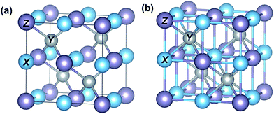
HH compounds are ternary intermetallics with a general formula XYZ, crystallizing in a cubic structure with the space group F![[4 with combining macron]](https://www.rsc.org/images/entities/char_0034_0304.gif) 3m (Fig. 1(a)).34 The most electropositive atom X (e.g., Ti, Zr, and Hf) and the most electronegative atom Z (e.g., Sn and Sb) form an ionic NaCl-type framework, while the Y atoms (e.g., Ni and Co) having intermediate electronegativity (with values very close to Z atoms) build the covalent ZnS-type sub-structure with Z atoms. One Y atom is located in the center of each XZ cubic framework as shown in Fig. 1(b). There are four such filled XZ cubic frameworks, while the other four are vacant, giving rise to excess volume in the unit cell. If this vacant site is completely filled by Y atoms, the full Heusler XY2Z structure type is obtained.35
3m (Fig. 1(a)).34 The most electropositive atom X (e.g., Ti, Zr, and Hf) and the most electronegative atom Z (e.g., Sn and Sb) form an ionic NaCl-type framework, while the Y atoms (e.g., Ni and Co) having intermediate electronegativity (with values very close to Z atoms) build the covalent ZnS-type sub-structure with Z atoms. One Y atom is located in the center of each XZ cubic framework as shown in Fig. 1(b). There are four such filled XZ cubic frameworks, while the other four are vacant, giving rise to excess volume in the unit cell. If this vacant site is completely filled by Y atoms, the full Heusler XY2Z structure type is obtained.35
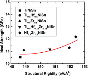
The chemical bonding in HH compounds can be described as a covalent zinc blende [YZ]n− sub-structure, with the Xn+ cation showing ionic interactions by donating the valence electrons to the sub-structure. The calculated electron localization function (ELF) for TiNiSn is in agreement with this description (Fig. 2): strong covalent interaction between Ni and Sn atoms ([NiSn]4−) and a strong ionic interaction of the Ti atoms (Ti4+) with the Ni–Sn sub-structure. The strength of the ionic bonding between Xn+ and [YZ]n− sub-structures depends on the degree of electropositivity of the X atoms, which becomes stronger with higher electropositive elements i.e. higher for Zr and much higher for Hf. We calculated the structural rigidity of (Ti, Hf, and Zr)NiSn compounds. The structural rigidity of TiNiSn (148.64 eV Å−2) is lower than that of Ti0.5Zr0.5NiSn (148.88 eV Å−2) and much lower than that of Ti0.5Hf0.5NiSn (151.96 eV Å−2), indicating that the ionic bonding interaction between Hf4+ and [NiSn]4− is stronger than that of Zr4+ and [NiSn]4−, and is much stronger than that of Ti4+ and [NiSn]4−.
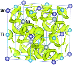 | ||
| Fig. 2 Framework of the TiNiSn compound combined with calculated isosurfaces (at a value of 0.45) of the electron localization function (ELF). The electron localization function (ELF) value, which ranges from 0 to 1, enables an effective and reliable analysis of covalent bonding and lone pair formation.36 The shared electrons between Ni and Sn atoms indicate a covalent bonding character, whereas the Ni–Ti and Ti–Sn interactions suggest an ionic bonding character, having no shared electrons. | ||
3.2 Elastic properties of TiNiSn
The elastic properties were calculated to provide valuable information on the stability and stiffness of TiNiSn. The elastic constants (C11, C12, and C44) were obtained by calculating the total energy as a function of various cell distortions δ from the optimized structure. Once the elastic constants are calculated, other related elastic properties such as the bulk modulus (B), shear modulus (G), Young's modulus (E), Poisson's ratio (v), and ductility index (B/G) can be computed using the Voigt–Reuss–Hill method.37 The predicted elastic mechanical properties (C11, C12, C44, B, G, E, v, and B/G) are listed in Table 1, which show reasonable agreement with previously reported ab initio results using the PBE functional.22,23,38,39 The discrepancy of the predicted results arises from the different convergence setup in VASP calculations. Different convergence criteria, like plane wave cutoff energy, electronic convergence energy difference, and ionic convergence criteria, will lead to different optimized structures, hence resulting in different elastic constants and elastic properties. For example, the bulk modulus (B) in this work and in ref. 38 is exactly the same. However, G, E, and B/G are different. Here, our optimized lattice parameter of TiNiSn is only 0.24% smaller than the experimental value of 5.926 Å. In ref. 38, the optimized lattice parameter of TiNiSn is a = 5.953 Å, 0.46% larger than the experimental value. Thus, the convergence criteria in this work are more reliable than those in ref. 38. Moreover, TiNiSn contains transition metals Ti and Ni. Here, we compared the elastic properties of TiNiSn with PBE and PBE + U (U = 2.0 eV for Ti and Ni, respectively) as listed in Table 1, and found that the U correction has minor influence on the mechanical properties of TiNiSn.| Method | C 11 (GPa) | C 12 (GPa) | C 44 (GPa) | B (GPa) | G (GPa) | E (GPa) | v | B/G |
|---|---|---|---|---|---|---|---|---|
| Our PBE | 223.85 | 81.25 | 64.54 | 128.78 | 67.16 | 171.65 | 0.28 | 1.92 |
| PBE + U | 216.22 | 81.84 | 62.65 | 126.63 | 64.43 | 165.26 | 0.28 | 1.96 |
| PBE22 | 196.41 | 82.16 | 60.61 | 120.24 | 59.19 | 152.54 | 0.29 | 2.03 |
| PBE38 | — | — | — | 128 | 75.52 | 189.28 | 0.25 | 1.69 |
| PBE23 | 264.94 | 89.24 | 87.85 | 147.81 | 87.84 | 219.96 | 0.25 | 1.68 |
| Expt39 | — | — | — | 121 | — | — | — |
Both the ductility ratio (B/G) and Poisson's ratio (v) can be used to estimate the ductility and brittleness of materials. A high B/G reflects the ductility and a low value corresponds to the brittle nature. Frantsevich suggested the critical value to be B/G = 2.67,40,41 but Pugh proposed a smaller value of B/G = 1.75.42 In our calculations (Table 1), the obtained B/G ratio (1.92) is smaller than Frantsevich's criteria but larger than Pugh's criteria. It is hard to estimate the ductility and brittleness from the B/G ratio. However, a material with Poisson's ratio (v) less than 0.33 generally behaves brittle, and otherwise behaves ductile.40 From the v listed in Table 1, we can conclude that TiNiSn is expected to behave brittle.
3.3 Shear induced failure mechanism of TiNiSn
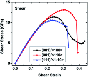
![[1 with combining macron]](https://www.rsc.org/images/entities/char_0031_0304.gif) 10〉 slip system exhibits the lowest ideal shear strength of 10.52 GPa, which is much lower than the ideal tensile strength of 20.73 GPa (Table S1†), indicating that it is the most likely slip surface under pressure. This value is much higher than the ideal shear strength of CoSb3 (7.17 GPa)33 and Mg2Si (4.54 GPa),43 suggesting that TiNiSn has a much higher mechanical robustness. After a softening stage, shear stress dramatically decreases at fracture strains of 0.334 and 0.381 along the (111)/〈
10〉 slip system exhibits the lowest ideal shear strength of 10.52 GPa, which is much lower than the ideal tensile strength of 20.73 GPa (Table S1†), indicating that it is the most likely slip surface under pressure. This value is much higher than the ideal shear strength of CoSb3 (7.17 GPa)33 and Mg2Si (4.54 GPa),43 suggesting that TiNiSn has a much higher mechanical robustness. After a softening stage, shear stress dramatically decreases at fracture strains of 0.334 and 0.381 along the (111)/〈![[1 with combining macron]](https://www.rsc.org/images/entities/char_0031_0304.gif) 10〉 and (001)/〈110〉 slip systems, respectively. However, the shear stress along the (001)/〈100〉 slip system slightly increases after a long softening stage from strain 0.243 to 0.413, suggesting a significant structural rearrangement at the minimum stress point (4.83 GPa). As the strain increases, this structural rearrangement continues to resist the external shear deformation, hence leading to the increasing shear stress, as shown in Fig. 3.
10〉 and (001)/〈110〉 slip systems, respectively. However, the shear stress along the (001)/〈100〉 slip system slightly increases after a long softening stage from strain 0.243 to 0.413, suggesting a significant structural rearrangement at the minimum stress point (4.83 GPa). As the strain increases, this structural rearrangement continues to resist the external shear deformation, hence leading to the increasing shear stress, as shown in Fig. 3.
| Mechanics | Shear | ||
|---|---|---|---|
| (001)/〈100〉 | (001)/〈110〉 | (111)/〈![[1 with combining macron]](https://www.rsc.org/images/entities/char_0031_0304.gif) 10〉 10〉 |
|
| Ideal strength (GPa) | 11.39 | 13.11 | 10.52 |
| Failure strain | — | 0.381 | 0.334 |
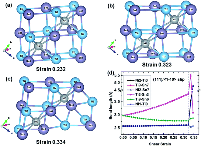
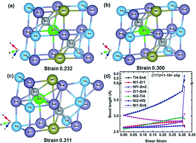
![[1 with combining macron]](https://www.rsc.org/images/entities/char_0031_0304.gif) 10〉 slip system. At 0.232 strain which corresponds to the maximum shear strength, the TiSn framework is distorted to resist the shear deformation. The TiSn framework is further distorted with increasing shear strain, but the structural rigidity gradually softens until reaching the strain 0.323, as shown in Fig. 4(b). At a fracture strain of 0.334, the TiSn framework reaches a limiting resistance. The TiSn framework with the vacancy center (the empty TiSn framework) collapses, and the shear stress is released, leading to the failure of TiNiSn. The typical bond lengths of Ni2–Ti3, Ti9–Sn7, Ni2–Sn7, Ti3–Sn3, Ti9–Sn6, and Ni1–Ti9 at various shear strains are plotted in Fig. 4(d). Ni2–Ti3, Ni2–Sn7, and Ni1–Ti9 bonds are slightly stretched during the shear process with the bond lengths increasing from 2.58 to 2.61 Å, indicating that these two kinds of bonds have a small contribution to the resistance of the deformation. This explains that shearing along the (111)/〈
10〉 slip system. At 0.232 strain which corresponds to the maximum shear strength, the TiSn framework is distorted to resist the shear deformation. The TiSn framework is further distorted with increasing shear strain, but the structural rigidity gradually softens until reaching the strain 0.323, as shown in Fig. 4(b). At a fracture strain of 0.334, the TiSn framework reaches a limiting resistance. The TiSn framework with the vacancy center (the empty TiSn framework) collapses, and the shear stress is released, leading to the failure of TiNiSn. The typical bond lengths of Ni2–Ti3, Ti9–Sn7, Ni2–Sn7, Ti3–Sn3, Ti9–Sn6, and Ni1–Ti9 at various shear strains are plotted in Fig. 4(d). Ni2–Ti3, Ni2–Sn7, and Ni1–Ti9 bonds are slightly stretched during the shear process with the bond lengths increasing from 2.58 to 2.61 Å, indicating that these two kinds of bonds have a small contribution to the resistance of the deformation. This explains that shearing along the (111)/〈![[1 with combining macron]](https://www.rsc.org/images/entities/char_0031_0304.gif) 10〉 slip system has the lowest ideal shear strength. The Ti9–Sn6 bond shrinks from 2.97 to 2.78 Å, with a compression ratio of 6.40% before the failure. Meanwhile, the Ti9–Sn7 and Ti3–Sn3 bond lengths rapidly increase from 2.97 to 3.79 Å, with a stretching ratio of 27.61% before the failure, indicating a strongly softened bond. At the fracture strain of 0.334, the breakage of highly softened Ti9–Sn7 and Ti3–Sn3 bonds represents the collapse of the TiSn framework, leading to the failure of TiNiSn.
10〉 slip system has the lowest ideal shear strength. The Ti9–Sn6 bond shrinks from 2.97 to 2.78 Å, with a compression ratio of 6.40% before the failure. Meanwhile, the Ti9–Sn7 and Ti3–Sn3 bond lengths rapidly increase from 2.97 to 3.79 Å, with a stretching ratio of 27.61% before the failure, indicating a strongly softened bond. At the fracture strain of 0.334, the breakage of highly softened Ti9–Sn7 and Ti3–Sn3 bonds represents the collapse of the TiSn framework, leading to the failure of TiNiSn.
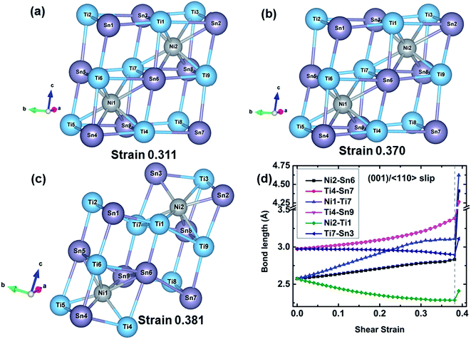
The structural changes of TiNiSn at various strains along the (001)/〈110〉 slip system are extracted, as shown in Fig. 5. The TiSn framework is distorted as the shear strain increases to 0.311 corresponding to the maximum shear strength. As the strain increases to 0.370 before the failure, the TiSn framework is further distorted while the rigidity decreases as indicated by gradually decreasing shear stress (Fig. 3). When the shear strain further increases to 0.381, the TiSn framework breaks, leading to the structural deconstruction, as shown in Fig. 5(c). The typical bond lengths of Ni2–Sn6, Ti4–Sn7, Ni1–Ti7, Ti4–Sn9, Ni2–Ti1, and Ti7–Sn3 bonds are plotted against shear strain in Fig. 5(d). The Ni1–Ti7 bond is stretched much faster (from 2.58 to 3.09 Å) than the Ni2–Sn6 bond (from 2.58 to 2.83 Å), and has a much higher stretching ratio of 19.77% at the 0.311 strain, as shown in Fig. 5(d). Following this the Ti4–Sn7 and Ti4–Sn9 bond lengths rapidly increase from 3.22 to 3.38 Å when the shear strain increases from 0.311 to 0.370, suggesting that the softening of these two bonds leads to the weakened rigidity of the TiSn framework. The Ti7–Sn3 and Ni2–Ti1 bonds shrink from 2.97 and 2.57 Å to 2.90 and 2.29 Å, respectively, before the failure. At a fracture strain of 0.381, the breakage of Ti4–Sn7 and Ti4–Sn9 bonds leads to the collapse of the TiSn framework, resulting in the failure of TiNiSn.
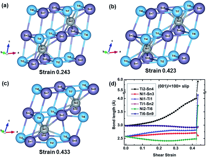
The atomic configurations and the typical bond lengths along the (001)/〈100〉 slip system are shown in Fig. 6. When the shear strain increases to 0.243 corresponding to the ideal shear strength, the structure is distorted to resist the deformation and reaches the maximal structural rigidity. With further increasing shear strain, the structural rigidity gradually decreases. At 0.423 strain, the structure has maximal rigidity. At 0.433 strain corresponding to the structural rearrangement, an empty TiSn framework rearranges to another structure which can continuously resist the shear deformation, resulting in the increasing shear stress with the increased shear strain as plotted in Fig. 3. The typical bond lengths of Ti2–Sn4, Ni1–Sn3, Ni1–Ti1, Ti1–Sn2, Ni2–Ti6, and Ti6–Sn9 are plotted against shear strain in Fig. 6(d). The Ti2–Sn4 bond rapidly softens after 0.243 strain, which leads to a decrease in the rigidity of the TiSn framework. The Ti2–Sn4 bond is stretched from 2.97 to 3.99 Å with a stretching ratio of 34.34% before the bond is broken. All the other bonds slightly stretch or shrink before the failure. At 0.433 strain, the breakage of the Ti2–Sn4 bond leads to the deconstruction of the TiSn framework and structural rearrangement.
The shear failure modes of TiNiSn clearly show that the empty TiSn framework collapses first but the Ni filled TiSn framework can still hold, as shown in Fig. 4–6. The empty TiSn framework is composed solely of Ti–Sn ionic bonds. The Ni filled TiSn framework contains Ni–Sn covalent bonds and Ni–Ti ionic bonds besides the Ti–Sn ionic bonds, indicating that the Ni filled TiSn framework is much more rigid than the empty TiSn framework. This explains why the empty TiSn framework collapses. In particular, the deconstruction of the empty TiSn framework can be attributed to the softening and breakage of Ti–Sn ionic bonds. The structural patterns in Fig. 4–6 also show that the TiSn framework resists external deformation until the ideal strength. The softening of Ti–Sn ionic bonds leads to the decreased rigidity of the TiSn framework in TiNiSn. Obviously, strengthening Ti–Sn ionic bonds increases the rigidity of the TiSn framework, leading to the enhanced ideal strength of TiNiSn.
We also studied the uniaxial tensile mechanics of TiNiSn, and found that the ideal tensile strength is much higher than the ideal shear strength of TiNiSn. The tensile failure modes of TiNiSn shown in Fig. S2–S4† also indicate that the softening and destruction of the TiSn framework lead to the structural failure. The detailed description of uniaxial tensile mechanics is shown in the ESI.†
Due to the nature of bonding, ionic bonds lead to brittle material properties, and covalent bonds are strong and directional.44 The breakage of Ti–Sn ionic bonds reveals the brittleness of TiNiSn, which agrees with our estimation from Poisson's ratio v (see Table 1). Alternatively, along [100] oriented tension, the Ni–Sn covalent bonds uniformly resist the external deformation until they break (Fig. S4†), verifying the strong directional feature of covalent bonds. Among all the shear and tensile deformations (Fig. 4–6 and S2–S4†), the Ni–Sn covalent bond has a lower stretching ratio than the Ni–Ti and Ti–Sn ionic bonds, indicating that it is the most rigid bond in TiNiSn. This rigidity explains why Ti–Sn bonds break while most of the Ni–Sn bonds still hold together.
3.4 Effect of doping of TiNiSn on mechanical properties
The ideal shear strength represents the maximal resistance on external deformation and plays a significant role in evaluating the mechanical robustness and the reliability of materials.30,32 Enhancing the ideal shear strength of TiNiSn is of significance to improve the mechanical robustness of TiNiSn and reliability of TE devices. We showed above that the deconstruction of the TiSn framework plays an essential role in the failure process of TiNiSn. To enhance the ideal strength of TiNiSn, we suggest improving the rigidity of the TiSn framework in the TiNiSn.The substitution of Ti by Hf and Zr elements to form (Ti, Hf, and Zr)NiSn alloys is confirmed to be an effective way to enhance the thermoelectric properties of TiNiSn.45–51 Herein, we investigate the effect of a mixture of Ti, Hf, and Zr on the ideal strength of (Ti, Hf, and Zr)NiSn. The most plausible slip system (111)/〈![[1 with combining macron]](https://www.rsc.org/images/entities/char_0031_0304.gif) 10〉 is chosen to impose the shear deformation on the doped systems (72 total atoms) of Ti0.5Hf0.5NiSn, Ti0.5Zr0.5NiSn, Ti0.5Hf0.25Zr0.25NiSn, and Hf0.5Zr0.5NiSn, respectively.
10〉 is chosen to impose the shear deformation on the doped systems (72 total atoms) of Ti0.5Hf0.5NiSn, Ti0.5Zr0.5NiSn, Ti0.5Hf0.25Zr0.25NiSn, and Hf0.5Zr0.5NiSn, respectively.
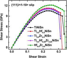
![[1 with combining macron]](https://www.rsc.org/images/entities/char_0031_0304.gif) 10〉 shear loading is plotted in Fig. 7, and the ideal strength and fracture strain are listed in Table 3. It clearly shows that (Ti, Hf, and Zr)NiSn alloys have superior mechanical properties such as secant modulus and ideal strength to TiNiSn, which arises from the enhanced rigidity of the TiSn framework by Hf and Zr atoms. In particular, a Hf atom is more effective than a Zr atom at enhancing the structural rigidity. This is shown in Table 3 with Ti0.5Hf0.5NiSn having a higher ideal strength compared to that of Ti0.5Zr0.5NiSn. This enhancement in structural rigidity by Hf and Zr substitutions leads to the highest ideal strength (12.17 GPa) of Hf0.5Zr0.5NiSn, as listed in Table 3. However, all the systems display a dramatically decreased shear stress and a small difference in the fracture strain (Fig. 7), suggesting that Hf and Zr atoms do not significantly affect the failure of TiNiSn.
10〉 shear loading is plotted in Fig. 7, and the ideal strength and fracture strain are listed in Table 3. It clearly shows that (Ti, Hf, and Zr)NiSn alloys have superior mechanical properties such as secant modulus and ideal strength to TiNiSn, which arises from the enhanced rigidity of the TiSn framework by Hf and Zr atoms. In particular, a Hf atom is more effective than a Zr atom at enhancing the structural rigidity. This is shown in Table 3 with Ti0.5Hf0.5NiSn having a higher ideal strength compared to that of Ti0.5Zr0.5NiSn. This enhancement in structural rigidity by Hf and Zr substitutions leads to the highest ideal strength (12.17 GPa) of Hf0.5Zr0.5NiSn, as listed in Table 3. However, all the systems display a dramatically decreased shear stress and a small difference in the fracture strain (Fig. 7), suggesting that Hf and Zr atoms do not significantly affect the failure of TiNiSn.
![[1 with combining macron]](https://www.rsc.org/images/entities/char_0031_0304.gif) 10〉 shear loading
10〉 shear loading
| Mechanics | (111)/〈![[1 with combining macron]](https://www.rsc.org/images/entities/char_0031_0304.gif) 10〉 Shear 10〉 Shear |
||||
|---|---|---|---|---|---|
| TiNiSn | Ti0.5Hf0.5NiSn | Ti0.5Zr0.5NiSn | Ti0.5Hf0.25Zr0.25NiSn | Hf0.5Zr0.5NiSn | |
| Ideal strength (GPa) | 10.52 | 11.29 | 11.09 | 11.16 | 12.17 |
| Failure strain | 0.334 | 0.323 | 0.311 | 0.311 | 0.346 |
Here, we examine the effect of the random structure on mechanics of Ti0.5Hf0.5NiSn, as plotted in Fig. S5 in the ESI.† Fig. S5(d)† clearly shows that the shear stress–strain responses along the (111)/〈![[1 with combining macron]](https://www.rsc.org/images/entities/char_0031_0304.gif) 10〉 slip system in ordered and random Ti0.5Hf0.5NiSn alloys are the same, indicating that the random structure has little effect on the mechanics of the Ti0.5Hf0.5NiSn system. Thus, even though ordered (Ti, Hf, and Zr)NiSn alloys were created in this work, the calculation results can refer to an accurate realization of alloys.
10〉 slip system in ordered and random Ti0.5Hf0.5NiSn alloys are the same, indicating that the random structure has little effect on the mechanics of the Ti0.5Hf0.5NiSn system. Thus, even though ordered (Ti, Hf, and Zr)NiSn alloys were created in this work, the calculation results can refer to an accurate realization of alloys.
![[1 with combining macron]](https://www.rsc.org/images/entities/b_char_0031_0304.gif) 10〉 shear load.
To further understand the failure modes of (Ti, Hf, and Zr)NiSn alloys, the atomic structures at critical strains and the typical bond lengths along the (111)/〈
10〉 shear load.
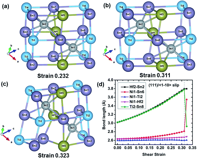
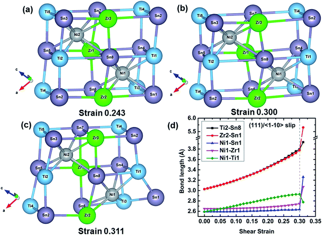
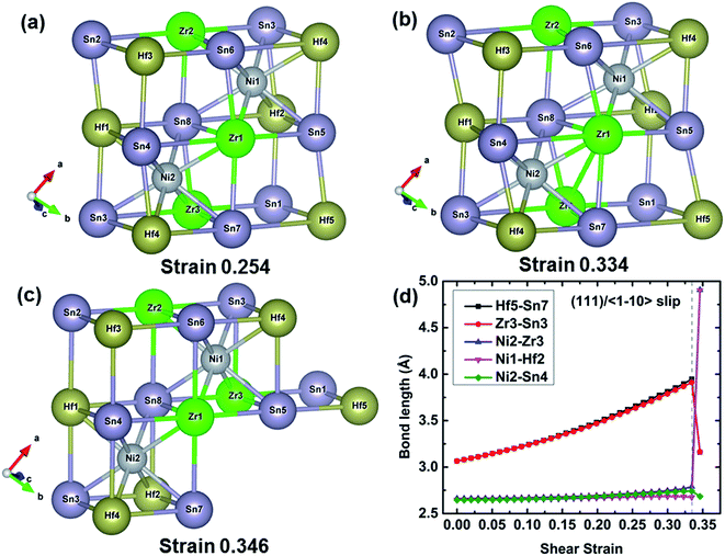
To further understand the failure modes of (Ti, Hf, and Zr)NiSn alloys, the atomic structures at critical strains and the typical bond lengths along the (111)/〈![[1 with combining macron]](https://www.rsc.org/images/entities/char_0031_0304.gif) 10〉 slip system are extracted, as shown in Fig. 8–11. In all the alloys, the XSn framework (X = Ti, Hf, and Zr elements) is distorted to resist the shear deformation. At the fracture strain, the collapse of the XSn framework leads to the failure of (Ti, Hf, and Zr)NiSn alloys. The average bond lengths in Fig. 8(d)–11(d) clearly show that the X–Sn bonds (X = Ti, Hf, and Zr) are stretched rapidly with the increasing shear strain, representing highly softening X–Sn bonds. This softening of X–Sn bonds leads to the decreased rigidity of the XSn framework. Further deformation leads to the breakage of X–Sn bonds, hence resulting in the collapse of the XSn framework and structural failure. In addition, the XSn framework in Ti0.5Hf0.5NiSn is rearranged to another structure as shown in Fig. 11(c), leading to a structural rearrangement.
10〉 slip system are extracted, as shown in Fig. 8–11. In all the alloys, the XSn framework (X = Ti, Hf, and Zr elements) is distorted to resist the shear deformation. At the fracture strain, the collapse of the XSn framework leads to the failure of (Ti, Hf, and Zr)NiSn alloys. The average bond lengths in Fig. 8(d)–11(d) clearly show that the X–Sn bonds (X = Ti, Hf, and Zr) are stretched rapidly with the increasing shear strain, representing highly softening X–Sn bonds. This softening of X–Sn bonds leads to the decreased rigidity of the XSn framework. Further deformation leads to the breakage of X–Sn bonds, hence resulting in the collapse of the XSn framework and structural failure. In addition, the XSn framework in Ti0.5Hf0.5NiSn is rearranged to another structure as shown in Fig. 11(c), leading to a structural rearrangement.
 | (1) |
| Bond | TiNiSn | Ti0.5Hf0.5NiSn | Ti0.5Zr0.5NiSn | Hf0.5Zr0.5NiSn | Ti0.5Hf0.25Zr0.25NiSn | |||||
|---|---|---|---|---|---|---|---|---|---|---|
| Length | SFC | Length | SFC | Length | SFC | Length | SFC | Length | SFC | |
| Ni–Sn | 2.57 | 3.98 | 2.59 | 3.71 | 2.59 | 3.69 | 2.64 | 2.87 | 2.58 | 3.86 |
| 2.62 | 3.06 | 2.64 | 2.87 | 2.66 | 2.61 | 2.60 | 3.56 | |||
| 2.63 | 2.95 | |||||||||
| Ni–Ti | 2.57 | 1.23 | 2.59 | 1.03 | 2.59 | 0.96 | 2.59 | 1.02 | ||
| Ni–Hf | 2.62 | 2.24 | 2.64 | 1.98 | 2.62 | 2.21 | ||||
| Ni–Zr | 2.64 | 2.21 | 2.66 | 2.02 | 2.64 | 2.27 | ||||
| Sn–Ti | 2.97 | 2.72 | 3.01 | 2.36 | 3.02 | 2.23 | 3.01 | 2.29 | ||
| Sn–Hf | 3.01 | 3.61 | 3.06 | 3.07 | 3.01 | 3.53 | ||||
| Sn–Zr | 3.02 | 3.67 | 3.06 | 3.31 | 3.01 | 3.77 | ||||
4. Conclusions
We applied density functional theory to examine the response along various tensile and shear deformations focusing on the intrinsic failure mechanism of TiNiSn. Among all shear and tensile deformations, we found that shearing along the (111)/〈![[1 with combining macron]](https://www.rsc.org/images/entities/char_0031_0304.gif) 10〉 slip system has the lowest ideal shear strength at 10.52 GPa. The Ni–Sn covalent bond is more rigid than the Ni–Ti and Ti–Sn ionic bonds. The softening of the Ti–Sn bond leads to the weakened rigidity of the TiSn framework as well as the reversible plastic deformation is witnessed. The breakage of the Ti–Sn bond leads to the collapse of the TiSn framework and structural failure of TiNiSn. The substitution of Ti by Hf and Zr atoms leads to stronger Ni–X and Sn–X (X = Hf and Zr) bonds compared to Ni–Ti and Sn–Ti, resulting in a more rigid XSn (X = Hf and Zr) framework compared to the TiSn framework in TiNiSn. Thus, a high ideal strength of 12.17 GPa is obtained for Hf0.5Zr0.5NiSn, with an increase of 15.69% compared with that of TiNiSn.
10〉 slip system has the lowest ideal shear strength at 10.52 GPa. The Ni–Sn covalent bond is more rigid than the Ni–Ti and Ti–Sn ionic bonds. The softening of the Ti–Sn bond leads to the weakened rigidity of the TiSn framework as well as the reversible plastic deformation is witnessed. The breakage of the Ti–Sn bond leads to the collapse of the TiSn framework and structural failure of TiNiSn. The substitution of Ti by Hf and Zr atoms leads to stronger Ni–X and Sn–X (X = Hf and Zr) bonds compared to Ni–Ti and Sn–Ti, resulting in a more rigid XSn (X = Hf and Zr) framework compared to the TiSn framework in TiNiSn. Thus, a high ideal strength of 12.17 GPa is obtained for Hf0.5Zr0.5NiSn, with an increase of 15.69% compared with that of TiNiSn.
Acknowledgements
This work is partially supported by the National Basic Research Program of China (973-program) under Project no. 2013CB632505, the 111 Project of China under Project no. B07040, Materials Project by Department of Energy Basic Energy Sciences Program under Grant No. EDCBEE, DOE Contract DE-AC02-05CH11231, and China Postdoctoral Science Foundation (408-32200031). Q. A. and W. A. G. were supported by the Defense Advanced Research Projects Agency (W31P4Q-13-1-0010, program manager, John Paschkewitz) and by the National Science Foundation (DMR-1436985, program manager, John Schlueter). U.A. acknowledges the financial assistance of The Scientific and Technological Research Council of Turkey.References
- L. E. Bell, Cooling, Heating, Generating Power, and Recovering Waste Heat with Thermoelectric Systems, Science, 2008, 321, 1457–1461 CrossRef CAS PubMed.
- G. J. Snyder and E. S. Toberer, Complex Thermoelectric Materials, Nat. Mater., 2008, 7, 105–114 CrossRef CAS PubMed.
- M. T. Barako, W. Park, A. M. Marconnet, M. Asheghi and K. E. Goodson, Thermal Cycling, Mechanical Degradation, and the Effective Figure of Merit of a Thermoelectric Module, J. Electron. Mater., 2013, 42, 372–381 CrossRef CAS.
- H. H. Xie, H. Wang, Y. Z. Pei, C. G. Fu, X. H. Liu, G. J. Snyder, X. B. Zhao and T. J. Zhu, Beneficial Contribution of Alloy Disorder to Electron and Phonon Transport in Half-Heusler Thermoelectric Materials, Adv. Funct. Mater., 2013, 23, 5123–5130 CrossRef CAS.
- S. Chen, K. C. Lukas, W. S. Liu, C. P. Opeil, G. Chen and Z. F. Ren, Effect of Hf Concentration on Thermoelectric Properties of Nanostructured N-Type Half-Heusler Materials HfxZr1-xNiSn0.99Sb0.01, Adv. Energy Mater., 2013, 3, 1210–1214 CrossRef CAS.
- C. G. Fu, T. J. Zhu, Y. Z. Pei, H. H. Xie, H. Wang, G. J. Snyder, Y. Liu, Y. T. Liu and X. B. Zhao, High Band Degeneracy Contributes to High Thermoelectric Performance in p-Type Half-Heusler Compounds, Adv. Energy Mater., 2014, 4, 1400600 CrossRef.
- C. G. Fu, T. J. Zhu, Y. T. Liu, H. H. Xie and X. B. Zhao, Band Engineering of High Performance p-Type FeNbSb Based Half-Heusler Thermoelectric Materials for Figure of Merit zT > 1, Energy Environ. Sci., 2015, 8, 216–220 CAS.
- Y. W. Chai, T. Oniki and Y. Kimura, Microstructure and Thermoelectric Properties of a ZrNi1.1Sn Half-Heusler Alloy, Acta Mater., 2015, 85, 290–300 CrossRef CAS.
- J. Carrete, N. Mingo, S. D. Wang and S. Curtarolo, Nanograined Half-Heusler Semiconductors as Advanced Thermoelectrics: An ab Initio High-Throughput Statistical Study, Adv. Funct. Mater., 2014, 24, 7427–7432 CrossRef CAS.
- S. R. Culp, S. J. Poon, N. Hickman, T. M. Tritt and J. Blumm, Effect of Substitutions on the Thermoelectric Figure of Merit of Half-Heusler Phases at 800 Degrees C, Appl. Phys. Lett., 2006, 88, 042106 CrossRef.
- C. Yu, T. J. Zhu, R. Z. Shi, Y. Zhang, X. B. Zhao and J. He, High-Performance Half-Heusler Thermoelectric Materials Hf1-xZrxNiSn1-ySby Prepared by Levitation Melting and Spark Plasma Sintering, Acta Mater., 2009, 57, 2757–2764 CrossRef CAS.
- Y. Gelbstein, N. Tal, A. Yarmek, Y. Rosenberg, M. P. Dariel, S. Ouardi, B. Balke, C. Felser and M. Köhne, Thermoelectric Properties of Spark Plasma Sintered Composites Based on TiNiSn Half -Heusler Alloys, J. Mater. Res., 2011, 26, 1919–1924 CrossRef CAS.
- S. J. Poon, D. Wu, S. Zhu, W. J. Xie, T. M. Tritt, P. Thomas and R. Venkatasubramanian, Half-Heusler Phases and Nanocomposites as Emerging High-ZT Thermoelectric Materials, J. Mater. Res., 2011, 26, 2795–2802 CrossRef CAS.
- A. Singh, S. Bhattacharya, C. Thinaharan, D. K. Aswal, S. K. Gupta, J. V. Yakhmi and K. Bhanumurthy, Development of Low Resistance Electrical Contacts for Thermoelectric Devices Based on n-Type PbTe and p-Type TAGS-85 (AgSbTe2)0.15(GeTe)0.85, J. Phys. D: Appl. Phys., 2009, 42, 015502 CrossRef.
- K. Bartholomé, B. Balke, D. Zuckermann, M. Kohne, M. Muller, K. Tarantik and J. Konig, Thermoelectric Modules Based on Half-Heusler Materials Produced in Large Quantities, J. Electron. Mater., 2014, 43, 1775–1781 CrossRef.
- C. G. Fu, S. Q. Bai, Y. T. Liu, Y. S. Tang, L. D. Chen, X. B. Zhao and T. J. Zhu, Realizing High Figure of Merit in Heavy-Band p-Type Half-Heusler Thermoelectric Materials, Nat. Commun., 2015, 6, 8144 CrossRef PubMed.
- K. H. Bae, S. M. Choi, K. H. Kim, H. S. Choi, W. S. Seo, I. H. Kim, S. Lee and H. J. Hwang, Power-Generation Characteristics After Vibration and Thermal Stresses of Thermoelectric Unicouples with CoSb3/Ti/Mo(Cu) Interfaces, J. Electron. Mater., 2015, 44, 2124–2131 CrossRef CAS.
- S. Gahlawat, R. He, S. Chen, L. Wheeler, Z. F. Ren and K. W. White, Elastic Constants Determined by Nanoindentation for p-Type Thermoelectric Half-Heusler, J. Appl. Phys., 2014, 116, 083516 CrossRef.
- G. Rogl and P. Rogl, Mechanical Properties of Skutterudites, Sci. Adv. Mater., 2011, 3, 517–538 CrossRef CAS.
- Y. Gelbstein, G. Gotesman, Y. Lishzinker, Z. Dashevsky and M. P. Dariel, Mechanical Properties of PbTe-Based Thermoelectric Semiconductors, Scr. Mater., 2008, 58, 25–254 CrossRef.
- Y. Gelbstein, J. Tunbridge, R. Dixon, M. J. Reece, H. Ning, R. Gilchrist, R. Summers, I. Agote, M. A. Lagos, K. Simpson, C. Rouaud, P. Feulner, S. Rivera, R. Torrecillas, M. Husband, J. Crossley and I. Robinson, Physical, Mechanical and Structural Properties of Nano-Structured Highly Efficient n- and p- Silicides for Practical Thermoelectric Applications, J. Electron. Mater., 2014, 43, 1703–1711 CrossRef CAS.
- P. Hermet, K. Niedziolka and P. Jund, A First-Principles Investigation of the Thermodynamic and Mechanical Properties of Ni-Ti-Sn Heusler and Half-Heusler Materials, RSC Adv., 2013, 3, 22176–22184 RSC.
- M. Hichour, D. Rached, R. Khenata, M. Rabah, M. Merabet, A. H. Reshak, S. Bin Omran and R. Ahmed, Theoretical Investigations of NiTiSn and CoVSn Compounds, J. Phys. Chem. Solids, 2012, 73, 975–981 CrossRef CAS.
- G. Kresse and J. Furthmuller, Efficiency of ab-initio Total Energy Calculations for Metals and Semiconductors Using a Plane-Wave Basis Set, Comput. Mater. Sci., 1996, 6, 15–50 CrossRef CAS.
- G. Kresse and J. Furthmuller, Efficient Iterative Schemes for ab initio Total-Energy Calculations Using a Plane-Wave Basis Set, Phys. Rev. B: Condens. Matter Mater. Phys., 1996, 54, 11169–11186 CrossRef CAS.
- G. Kresse and D. Joubert, From Ultrasoft Pseudopotentials to the Projector Augmented-Wave Method, Phys. Rev. B: Condens. Matter Mater. Phys., 1999, 59, 1758–1775 CrossRef CAS.
- J. Perdew, K. Burke and M. Ernzerhof, Generalized Gradient Approximation Made Simple, Phys. Rev. Lett., 1996, 77, 3865–3868 CrossRef CAS PubMed.
- L. Offernes, P. Ravindran, C. W. Seim and A. Kjekshus, Prediction of composition for stable half-Heusler phases from electronic-band-structure analyses, J. Alloys Compd., 2008, 458, 47–60 CrossRef CAS.
- J. Yang, H. M. Li, T. Wu, W. Q. Zhang, L. D. Chen and J. H. Yang, Evaluation of Half-Heusler Compounds as Thermoelectric Materials Based on the Calculated Electrical Transport Properties, Adv. Funct. Mater., 2008, 18, 2880–2888 CrossRef CAS.
- D. Roundy, C. R. Krenn, M. L. Cohen and J. W. Morris, Ideal Shear Strengths of fcc Aluminum and Copper, Phys. Rev. Lett., 1999, 82, 2713–2716 CrossRef CAS.
- Q. An, W. A. Goddard and T. Cheng, Atomistic Explanation of Shear-Induced Amorphous Band Formation in Boron Carbide, Phys. Rev. Lett., 2014, 113, 095501 CrossRef PubMed.
- S. Ogata, J. Li and S. Yip, Ideal Pure Shear Strength of Aluminum and Copper, Science., 2002, 298, 807–811 CrossRef CAS PubMed.
- G. D. Li, Q. An, W. J. Li, W. A. Goddard, P. C. Zhai, Q. J. Zhang and G. J. Snyder, Brittle Failure Mechanism in Thermoelectric Skutterudite CoSb3, Chem. Mater., 2015, 27, 6329–6336 CrossRef CAS.
- F. Casper, T. Graf, S. Chadov, B. Balke and C. Felser, Half-Heusler Compounds: Novel Materials for Energy and Spintronic Applications, Semicond. Sci. Technol., 2012, 27, 063001 CrossRef.
- T. Graf, C. Felser and S. S. P. Parkin, Simple Rules for the Understanding of Heusler Compounds, Prog. Solid State Chem., 2011, 39, 1–50 CrossRef CAS.
- B. Silvi and A. Savin, Classification of Chemical Bonds Based on Topological Analysis of Electron Localization Functions, Nature, 1994, 371, 683–686 CrossRef CAS.
- D. H. Chung, Elastic Moduli of Single-Crystal and Polycrystalline MgO, Philos. Mag., 1963, 8, 833–841 CrossRef CAS.
- K. Kirievsky, M. Shlimovich, D. Fuks and Y. Gelbstein, An ab Initio Study of the Thermoelectric Enhancement Potential in Nano-Grained TiNiSn, Phys. Chem. Chem. Phys., 2014, 16, 20023–20029 RSC.
- C. Colinet, P. Jund and J. C. Tedenac, NiTiSn a Material of Technological Interest: Ab Initio Calculations of Phase Stability and Defects, Intermetallics, 2014, 46, 103–110 CrossRef CAS.
- I. N. Frantsevich, F. F. Voronov and S. A. Bokuta, Elastic Constants and Elastic Moduli of Metals and Insulators Handbook, ed. I. N. Frantsevich, Naukuva Dumka Kiev, 1983, pp. 60–180 Search PubMed.
- G. Vaitheeswaran, V. Kanchana, R. S. Kumar, A. L. Cornelius, M. F. Nicol, A. Svane, A. Delin and B. Johansson, High-Pressure Structural, Elastic, and Electronic Properties of the Scintillator Host Material KMgF3, Phys. Rev. B: Condens. Matter Mater. Phys., 2007, 76, 014107 CrossRef.
- S. F. Pugh, Relations between the Elastic Moduli and the Plastic Properties of Polycrystalline Pure Metals, Philos. Mag., 1954, 45, 823–843 CrossRef CAS.
- T. W. Fan, J. L. Ke, L. Fu, B. Y. Tang, L. M. Peng and W. J. Ding, Ideal Strength of Mg2X (X = Si, Ge, Sn and Pb) from First-Principles, J. Magnesium Alloys, 2013, 1, 163–168 CrossRef CAS.
- H. Y. Niu, X. Q. Chen, P. T. Liu, W. W. Xing, X. Y. Cheng, D. Z. Li and Y. Y. Li, Extra-Electron Induced Covalent Strengthening and Generalization of Intrinsic Ductile-to-Brittle Criterion, Sci. Rep., 2012, 2, 718 Search PubMed.
- S. Sakurada and N. Shutoh, Effect of Ti Substitution on the Thermoelectric Properties of (Zr,Hf)NiSn Half-Heusler Compounds, Appl. Phys. Lett., 2005, 86, 082105 CrossRef.
- R. A. Downie, S. A. Barczak, R. I. Smith and J. W. G. Bos, Compositions and Thermoelectric Properties of XNiSn (X = Ti, Zr, Hf) Half-Heusler Alloys, J. Mater. Chem. C, 2015, 3, 10534–10542 RSC.
- R. A. Downie, D. A. MacLaren and J. W. G. Bos, Thermoelectric Performance of Multiphase XNiSn (X = Ti, Zr, Hf) Half-Heusler Alloys, J. Mater. Chem. A, 2014, 2, 6107–6114 CAS.
- E. Rausch, B. Balke, S. Ouardi and C. Felser, Enhanced Thermoelectric Performance in the p-Type Half-Heusler (Ti/Zr/Hf)CoSb0.8Sn0.2 System via Phase Separation, Phys. Chem. Chem. Phys., 2014, 16, 25258–25262 RSC.
- H. Y. Geng and H. Zhang, Effects of Phase Separation on the Thermoelectric Properties of (Ti, Zr, Hf)NiSn Half-Heusler Alloys, J. Appl. Phys., 2014, 116, 033708 CrossRef.
- S. Chen and Z. F. Ren, Recent Progress of Half-Heusler for Moderate Temperature Thermoelectric Applications, Mater. Today, 2013, 16, 387–395 CrossRef CAS.
- T. J. Zhu, C. G. Fu, H. H. Xie, Y. T. Liu and X. B. Zhao, High Efficiency Half-Heusler Thermoelectric Materials for Energy Harvesting, Adv. Energy Mater., 2015, 5, 1500588 CrossRef.
- A. Walle, M. Asta and G. Ceder, The Alloy Theoretic Automated Toolkit: A User Guide, CALPHAD: Comput. Coupling Phase Diagrams Thermochem., 2002, 26, 539–553 CrossRef.
Footnote |
| † Electronic supplementary information (ESI) available. See DOI: 10.1039/c6ta04123j |
| This journal is © The Royal Society of Chemistry 2016 |

