
 Open Access Article
 This Open Access Article is licensed under a
 Creative Commons Attribution 3.0 Unported Licence
Equilibrium binding energies from fluctuation theorems and force spectroscopy simulations
Emma
Hodges
ab,
B. M.
Cooke
b,
E. M.
Sevick
c,
Debra J.
Searles
 de,
B.
Dünweg
afg and
J. Ravi
Prakash
*a
de,
B.
Dünweg
afg and
J. Ravi
Prakash
*a
aDepartment of Chemical Engineering, Monash University, Melbourne, VIC 3800, Australia. E-mail: ravi.jagadeeshan@monash.edu; Fax: +61-9905-5686; Tel: +61-9905-3274
bMonash Biomedicine Discovery Institute and Department of Microbiology, Monash University, VIC 3800, Australia
cResearch School of Chemistry, Australian National University, Canberra, ACT 0200, Australia
dAIBN Centre for Theoretical and Computational Molecular Science, University of Queensland, Brisbane, QLD 4072, Australia
eSchool of Chemical and Molecular Biosciences, University of Queensland, Brisbane, QLD 4072, Australia
fMax Planck Institute for Polymer Research, Ackermannweg 10, 55128 Mainz, Germany
gCondensed Matter Physics, TU Darmstadt, Hochschulstraße 12, 64289 Darmstadt, Germany
First published on 14th November 2016
Abstract
Brownian dynamics simulations are used to study the detachment of a particle from a substrate. Although the model is simple and generic, we attempt to map its energy, length and time scales onto a specific experimental system, namely a bead that is weakly bound to a cell and then removed by an optical tweezer. The external driving force arises from the combined optical tweezer and substrate potentials, and thermal fluctuations are taken into account by a Brownian force. The Jarzynski equality and Crooks fluctuation theorem are applied to obtain the equilibrium free energy difference between the final and initial states. To this end, we sample non-equilibrium work trajectories for various tweezer pulling rates. We argue that this methodology should also be feasible experimentally for the envisioned system. Furthermore, we outline how the measurement of a whole free energy profile would allow the experimentalist to retrieve the unknown substrate potential by means of a suitable deconvolution. The influence of the pulling rate on the accuracy of the results is investigated, and umbrella sampling is used to obtain the equilibrium probability of particle escape for a variety of trap potentials.
1 Introduction
The adhesion of a cell to a substrate1–3 occurs in a number of biophysical contexts, and is hence a very important phenomenon to study. Beyond its relevance for understanding biological phenomena in general, many clinical applications in both diagnostics and therapeutics fundamentally involve adhesion. Examples include: (i) the sequestration of red blood cells in small blood vessels due to infection with malaria,4–7 (ii) the growth of metastases in cancer,8–10 and (iii) the formation of platelets at the site of a vascular injury.11 A variety of experimental techniques have been developed12 to measure the adhesive properties of a single cell, such as atomic-force microscopy,13–16 surface-force apparatus measurements,17 micropipette manipulation,18–20 as well as magnetic21 and optical22–24 tweezers. All these methods subject the cell to external time-dependent forces, with the aim of quantifying the energetics of the binding.The theoretical framework to analyse such experiments are the recently developed non-equilibrium work theorems,25,26 most notably the Jarzynski theorem,27,28 and Crooks fluctuation theorem,29–31 which have been used with great success to interpret data from both computer simulations and experiments.32–37 These theorems combine in a coherent fashion the three salient aspects of the experiments, which are (i) the system's equilibrium statistical physics (in particular the binding enthalpy), (ii) the fact that time-dependent manipulation necessarily implies non-equilibrium statistical physics (where the degree of deviation from equilibrium is determined by the pulling speed or a similar parameter), and (iii) the influence of thermal fluctuations. The central quantity of the theorems is the non-equilibrium work that the external forces do on the system. As soon as the external driving happens on a time scale that is faster than the typical relaxation times of the system, the non-equilibrium work is no longer simply given by the free energy difference between final and initial state (as would be the case for infinitely slow or quasi-static driving), but rather acquires a dissipative contribution, which, as a result of thermal fluctuations, has a statistical distribution of values. The theorems make detailed statements on the relation between the probability distribution of the non-equilibrium work and the underlying equilibrium free energies, and are hence immensely useful to obtain the latter under experimental conditions that cannot be considered as quasi-static. Essentially the extraction of equilibrium properties from the non-equilibrium work distribution is tantamount to reweighting the latter. Therefore, the theorems, although in theory being applicable to a large class of physical situations, have limitations in practice, since the equilibrium free energy difference should not differ from the mean non-equilibrium work by more than a few standard deviations – and this becomes more and more unfavourable both with increasing dissipation and increasing system size. In practice, this means that a reliable acquisition of equilibrium properties requires more and more trajectories over which one needs to average.27,28 In this context, it should be noted that the theorems always consider transitions from an equilibrium initial state to a final state, which is typically out of equilibrium. These states are not given by some reaction coordinate of the system, but rather by the external driving. Furthermore, we would like to mention that not only free energies, but also other equilibrium properties (like e.g. the probability of attachment) can be obtained in an analogous fashion by a suitable reweighting (or “umbrella sampling”) procedure.
Binding between cells is complex and involves a slew of interactions, which are both specific and non-specific.38–40 The most important ingredient, however, are bonds that arise from receptor–ligand pairs. Typically, a single receptor–ligand interaction is fairly strong, i.e., of order of few kBT to 100kBT, where kB is Boltzmann's constant and T the absolute temperature at ambient conditions,17,41i.e. kBT ≃ 4 pN nm. Moreover, cell adhesion will in most cases involve many ligands, giving rise to a net total interaction of typically several hundred kBT. The mechanical detachment of a cell from a “substrate” to which it is bound via receptor–ligand pairs (the latter can for example be another cell, or a ligand-coated bead) is thus a very complex process.38,42 In a highly simplified picture, we envision it to be roughly analogous to the pulling-off of a plaster from skin, or to the pinch-off of a water droplet from a dripping faucet. In optical tweezer experiments43 we have observed that the same external force can be sufficient to break some cell–substrate pairs but insufficient to break others of the same type. In our opinion, this provides an indication that the underlying dynamics matter, and this will depend on details of variables such as the number of receptor–ligand pairs, their density, and their geometrical arrangement. At any rate, this means that a faithful modeling of cell–substrate detachment or attachment would need to take into account a large arrangement of receptor–ligand bonds, and their (elastic) interactions. The single pair, in turn, is weak enough that thermal fluctuations crucially contribute to its formation and breaking.
As a first step in the modeling of micromechanical manipulation of cell attachment and detachment, we focus in the present paper on the case of just a single ligand–receptor pair. This is clearly the easiest situation, since in principle this allows us to just consider a single coordinate x as a degree of freedom, which may be viewed as the cell–substrate distance. This degree of freedom can then be viewed as subject to (i) forces from the cell–substrate interaction, (ii) forces from the time-dependent external pulling, and (iii) thermal agitation. This situation is less artificial than one might think at first glance, since it is experimentally possible to modify the adhesive properties of cells through gene-knockout techniques and/or inhibitors,44–48 such that receptor–ligand interactions are systematically turned off. The aim of the present theoretical study is to demonstrate that in this weak-binding situation the theorems can actually be applied practically to obtain reliable results on free energies, and, as a consequence, on the binding energetics. To do this, we study the attachment or detachment process within the framework of a very simple theoretical model, whose dynamics is simulated by means of Brownian Dynamics. An important aspect here is the fact that the simulation parameters (strength and range of interactions, pulling speed) roughly match those of real experiments. In the subsequent sections we will provide details on the choice of parameters, and discuss the relation between the free energies from the fluctuation theorems on the one hand, and the binding forces on the other.
It should be emphasised that our numerical model is fairly generic and therefore in principle applicable to any micromechanical manipulation that detaches one object from another (or attaches it to it), as long as this process can be described by a single reaction coordinate, and involves energies that are roughly comparable with kBT. However, what we have principally in mind are experiments with optical tweezers. We believe this technique has a great potential in the future, since it is fairly non-invasive, and provides good quantitative control over the external forces involved. For this reason, we choose our parameters in rough accordance with a typical tweezer experiment, and also use a nomenclature that refers to this situation. More precisely, we think of a cell tightly “glued” to a glass surface,22 while a ligand-coated bead is moved due to the influence of a time-dependent (harmonic) tweezer potential. The forces that the cell exerts on the bead are then described by a fixed (not time-dependent) “membrane potential”.
It is worth noting that fluctuation theorems have already been used to computationally calculate binding free energies in drug–receptor systems.32,33 These computations involve deterministic nonequilibrium molecular dynamics of ligand–receptor pairs whose molecular properties, such as Lennard-Jones parameters and force fields are known. In this paper, the analysis of single cell detachment events will be described and the usefulness of fluctuation theorems demonstrated, using data generated by stochastic simulation of a model cell and substrate. Since the situation in the numerical study is fairly similar to a typical experiment, we believe that this also demonstrates the usefulness of the approach to experimentally estimate the strength of binding – with the caveat that the experiments will be less accurate, since it is experimentally not possible to study ![[scr O, script letter O]](https://www.rsc.org/images/entities/char_e52e.gif) (106) trajectories, as was done in the present investigation.
(106) trajectories, as was done in the present investigation.
The remainder of the paper is organised in the following manner: First, details of the Langevin simulation will be presented, including code validation. Second, the Jarzynski and Crooks fluctuation theorems are shown to be valid for this two state system. As a result, non-equilibrium work trajectories, calculated for the different trap velocities, can be used to obtain the equilibrium free energy difference between the final and the initial state. We will also briefly outline (although this has not been done in the present work) how this information can in principle be used to retrieve the membrane potential, which in an experiment is of course unknown. Third, limitations of numerical calculations using the fluctuation theorems will be discussed and illustrated with the use of cumulants. Finally, umbrella sampling will be used to derive equilibrium values such as the probability of detachment or adhesion for a variety of different trap potentials.
2 Problem formulation
2.1 The model unbinding experiment
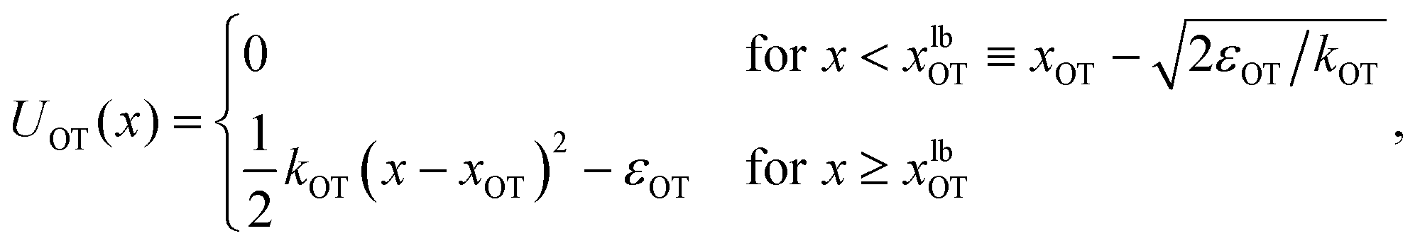
Truncated harmonic potentials, as shown in Fig. 1(a) and (b), are used to describe the interaction of the bead with both the membrane and the optical trap. These potentials are made dimensionless by scaling with the natural energy scale kBT, and defined by the expressions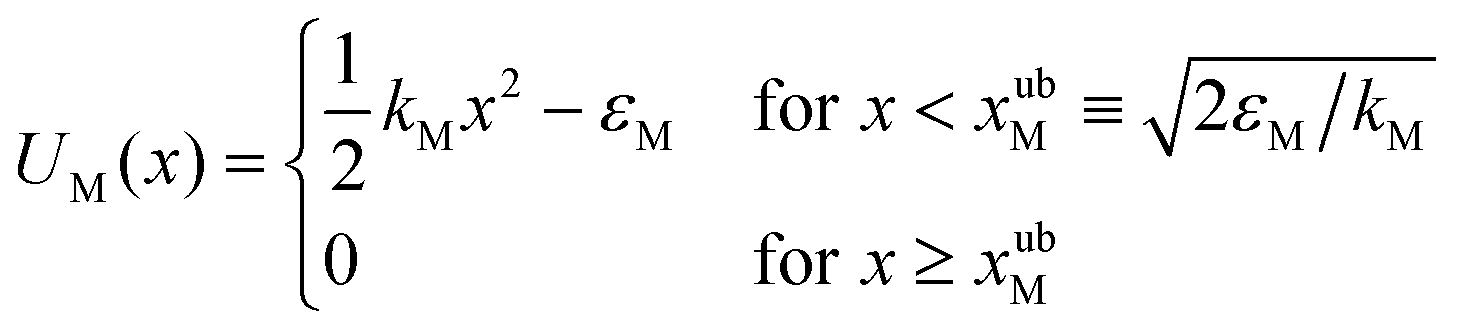 | (1) |
 | (2) |
 , where ks is a typical spring constant. We now choose the dimensionless parameters εM and εOT of order unity, which means that the involved energy scales are (kBT), as in the envisioned experiments. Furthermore, we assume that the spring constant ks is a value that corresponds to a typical optical trap strength of (10−3 pN nm−1),17 implying that kOT is a dimensionless parameter of order unity. At ambient conditions, kBT ≃ 4 pN nm, meaning that a typical thermal displacement within the trap (which is our unit of length) is several tens of nanometers. The typical displacements that we observe for cell detachment43 are of similar order, and therefore we set kM as a parameter of order unity as well.
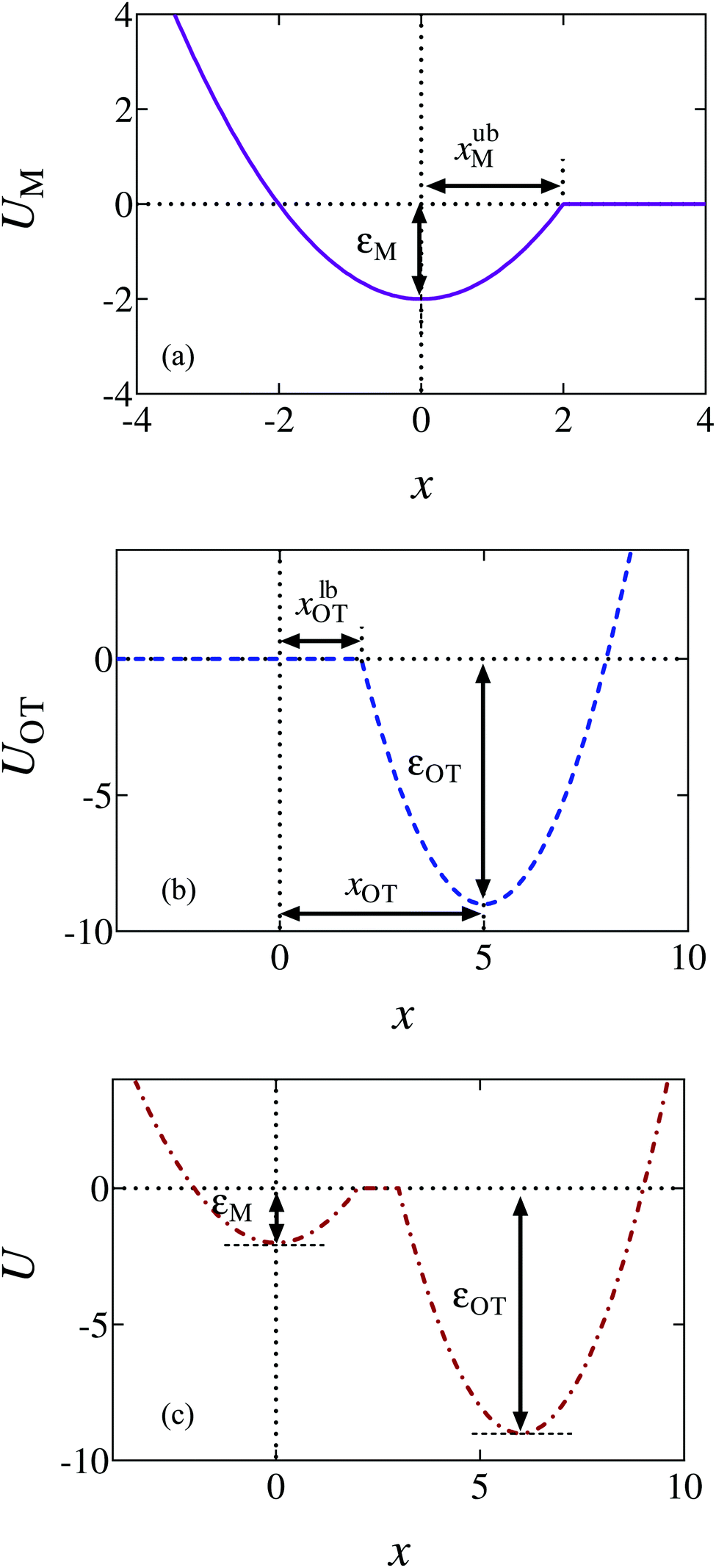 | ||
| Fig. 1 Schematic diagrams of the potentials. (a) The membrane potential (held stationary at all times). (b) The optical trap potential. The minimum, xOT, changes linearly with time as the optical trap is moved at a constant speed vOT to a final position, xfinalOT = 6. (c) The total potential, U = UM + UOT, experienced by the bead at some time t > 0. In order to detach from the membrane the bead needs an energy greater than εM, while in order for the bead to go from being unattached to attached, it would require an energy of order εOT or greater. | ||
The repulsive segment of the membrane potential (−∞<x ≤ 0) accounts for the impenetrability of the membrane to the bead, while the attractive segment (0<x ≤ xubM) represents the adhesive force exerted by the membrane on the bead (Fig. 1(a)). Beyond this distance, the bead detaches from the membrane and the influence on the bead by the membrane potential becomes negligible. Note that the minimum of the potential is held fixed at the origin (x = 0) for all time. Traditionally optical tweezer potentials are represented by harmonic wells.37,49 However, for investigations of detachment or attachments one should take into account that the optical trap has a finite range of attraction as well, such that a truncated harmonic potential is more reasonable. In principle this consideration holds for both branches x < xOT and x > xOT, where xOT is the (time-dependent) location of the minimum of UOT. However, it is crucially important only for x < xOT because this controls the energy barrier between the membrane and the trap potential. For x > xOT we do not truncate the tweezer potential, in order to obtain finite expressions in the equilibrium statistical mechanics of the system: If the total potential would exhibit an infinite range of vanishing potential, then this region would correspond to an infinite translational entropy, meaning that at any finite temperature there could be no equilibrium adsorption of the bead. Dynamically, this behavior would correspond to “evaporation” of the bead at sufficiently long times. It is therefore reasonable to study the particle in a potential that results in a converging partition function, and by this to strictly disregard such “evaporation” events (which, in a typical experiment, are anyway not observed). These considerations lead us to assume a model tweezer potential UOT as depicted in Fig. 1(b). The total potential, U(x) = UM(x) + UOT(x), at some time t > 0, is shown schematically in Fig. 1(c).
The optical trap potential minimum is located at the origin at time t = 0, i.e., xOT(t = 0) = 0. At later times, the optical trap is translated horizontally linearly with time, at varying speeds vOT (i.e., xOT(t) = vOTt), in order to simulate the process of bead detachment by the optical trap. The final position of the trap minimum is always at a fixed location, xfinalOT = 6, regardless of the value of vOT. The summed potential U is time dependent because of the time dependence of the optical potential. For the purpose of illustration, the shapes of the membrane and optical trap potentials, along with the summed potential, during the course of the simulation, at three different locations of the optical trap minimum are shown in Fig. 2.
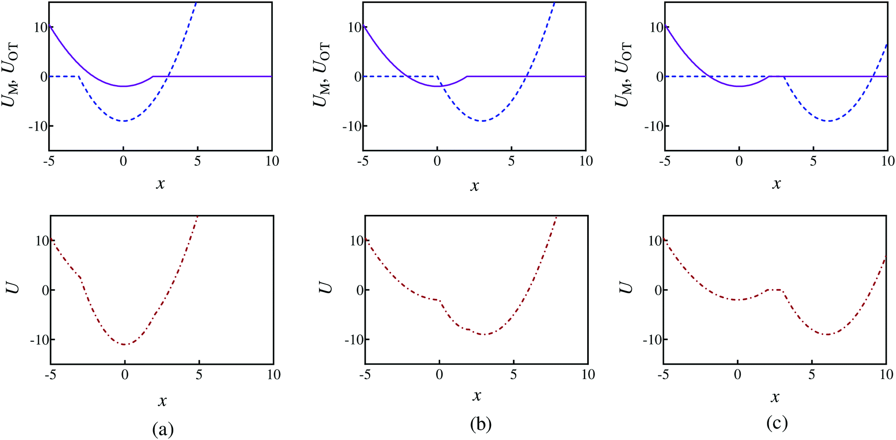 | ||
| Fig. 2 Potential energy profiles when the optical trap minimum is at three different locations and corresponding to parameter set 1 in Table 1. The first row shows the membrane (purple solid line) and optical trap (blue dashed line) potentials separately, whilst row two shows the summed potential (red dashed-dot line). Potential shapes at: (a) xOT = 0, (b) xOT = 0.5xfinalOT, and (c) xOT = xfinalOT. | ||
The relative ease of attachment and detachment is controlled by the magnitudes of the barrier heights for the membrane (εM) and the optical tweezer (εOT) potentials, respectively, and also by their respective strengths kM and kOT. In order to model different adhesive interactions between the bead and the membrane, the barrier heights and spring constants can be changed appropriately. In the present work, we choose three different sets of values for these parameters (given in Table 1), allowing different scenarios to be tested, as illustrated in Fig. 3. In Fig. 3(a), the membrane potential is weaker than the optical trap in both strength and depth. In Fig. 3(b), both the potentials have the same strength and depth, with the dimensional depth being of order 10kBT, while in Fig. 3(c), their dimensional depths are of order 1kBT. As will be seen subsequently, these three different scenarios lead to considerably different adhesive behaviour.
| Parameter sets | |||
|---|---|---|---|
| 1 | 2 | 3 | |
| k M | 1 | 2 | 1 |
| k OT | 2 | 2 | 1 |
| ε M | 2 | 9 | 2 |
| ε OT | 9 | 9 | 2 |
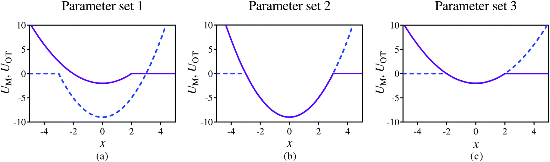 | ||
| Fig. 3 Snapshots of the membrane (purple solid line) and optical tweezer (blue dashed line) potentials at time t = 0, at three different dimensionless values of well depths, and membrane and trap strengths, as given in Table 1. | ||
2.2 The Langevin equation
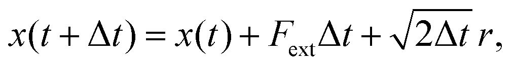
In the absence of inertia, the time evolution of the particle's position x(t), subject to an external force due to the presence of the membrane and optical potentials, and subject to thermal fluctuations, is described by a Langevin equation | (3) |
| 〈Frand〉 = 0 |
| 〈Frand(t)Frand(t′)〉 = 2δ(t − t′) | (4) |
 | (5) |
Details of time step sizes and the number of trajectories used in the simulations are given in the context of the various results discussed below.
Assuming a typical bead radius of 4 μm, and an aqueous environment with viscosity 10−3 Pa s, we find a Stokes friction coefficient of 0.075 × 10⁻³ pN s nm−1, meaning that for a spring constant of 10−3 pN nm−1 our unit of time is 0.075 seconds.
The non-equilibrium aspect of the computer experiment comes in through the finite pulling rate v (the velocity at which the location of the tweezer potential travels). For this we choose dimensionless values between 0.01 and 1. In experimental units, this means that even for the fastest process we pull the bead on a time scale of not much less than roughly 0.1 seconds, over a length scale of a few ten nanometers, which means that the simulated process corresponds well to experimentally feasible scales.
2.3 Fluctuation theorems
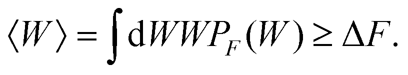
The initial and final states of our system are respectively defined as (i) xOT = 0, a situation where the tweezer potential keeps the bead at a location close to the membrane, and (ii) xOT = xfinalOT where it has moved the bead quite far away from it, such that it feels only the force from the optical trap. The fluctuation theorems are concerned with the free energy difference ΔF between these two states.If the unbinding is carried out isothermally and infinitesimally slowly, then ΔF is equal to the work W performed during the process. On the other hand, if the unbinding experiment is carried out at a finite rate over a period of time tD, the work performed will not be unique. Rather, an ensemble of such unbinding experiments will lead to a distribution of work values, PF(W) (where the subscript ‘F’ indicates the experiment is carried out in the forward direction, from the cell and bead being bound together to being unbound). Note that in this scenario, it is possible that at the end of the experiment, the bead remains close to the cell, even though work has been performed. In the quasi-static limit tD→∞, PF(W)→δ(W − ΔF). For finite rates of detachment, however,
 | (6) |
The great advance that has been made with the recently developed fluctuation theorems is that, contrary to the suggestion of eqn (6), a knowledge of the non-equilibrium work distribution is sufficient to determine the equilibrium free energy ΔF exactly.
The two fluctuation theorems that are primarily used in this work are the Crooks fluctuation theorem,29–31 and the Jarzynski equality.27,28 Both these theorems are based on the following set of assumptions. The system, whose dynamics is in our case stochastic and Markovian, is driven by an external perturbation from an initial equilibrium state, to a final state that is not necessarily at equilibrium. The external parameter driving the perturbation at a finite rate from the initial to the final state is denoted by λ, with values λ0 in the initial equilibrium state, and λf in the final state.
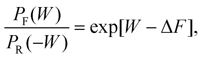
The Crooks fluctuation theorem states that29–31
 | (7) |
Eqn (7) clearly suggests that the value of work W* at which PF(W*) = PR(−W*), is nothing but the equilibrium free energy difference between the initial and final states. We use this result subsequently in order to estimate the free energy of binding.
The Jarzynski equality in its original form27,28 only considers perturbations from λ0 to λf, and states that
| 〈e−W〉F = e−ΔF, | (8) |
The experimental and practical relevance of these relations becomes clear when considering the defining relation for the free energy,
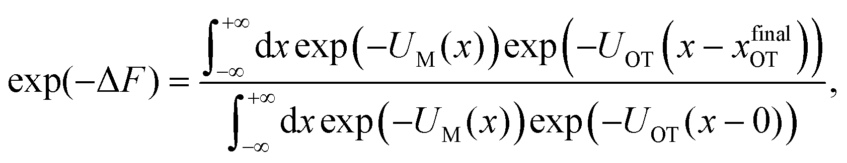 | (9) |
 | (10) |
| ϕ(x − xOT) = exp(−UOT(x − xOT)), | (11) |
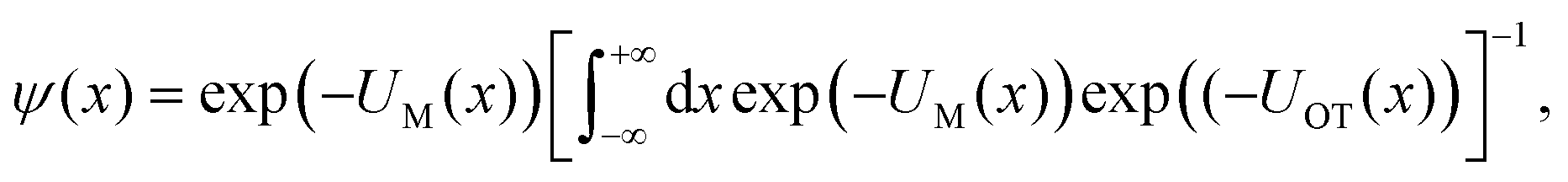 | (12) |
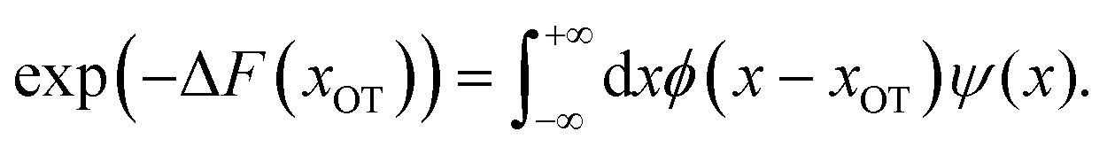 | (13) |
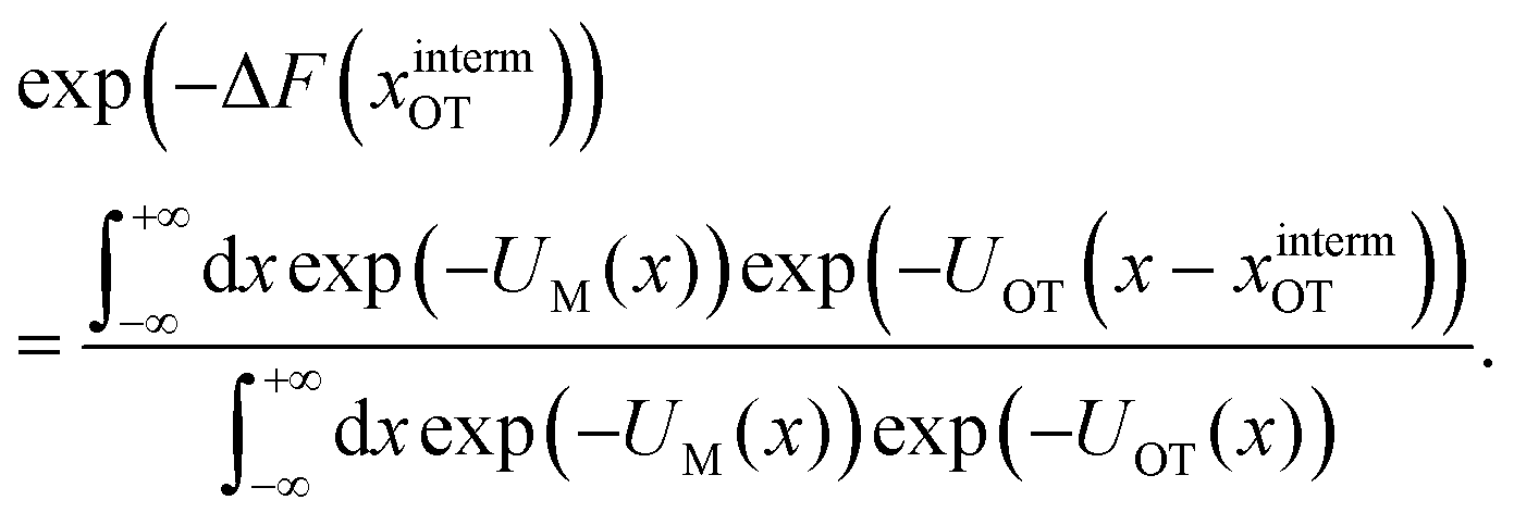
In other words, the exponential of the free energy profile, which is experimentally accessible via the fluctuation theorems, is nothing but the convolution of the known Boltzmann factor of the tweezer potential with the unknown Boltzmann factor of the membrane potential. Therefore, it should be possible to retrieve the latter by just a numerical deconvolution, assuming that the free energy profile is known with sufficient accuracy. More precisely, the procedure yields UM up to an unknown constant, which is however obviously irrelevant. Mapping out the membrane potential is, in our opinion, the ideal goal of such experiments. In the present work, we do not perform this program, but rather confine ourselves to the simpler task of just determining ΔF for a single final state.
2.4 Non-equilibrium work
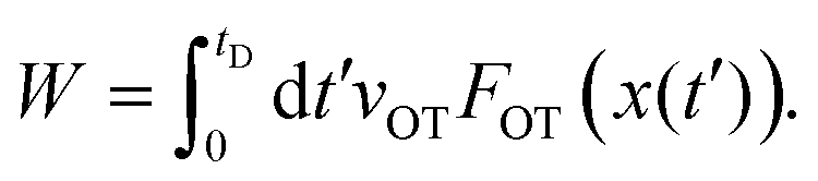
The application of the fluctuation theorems requires the determination of the distribution of work PF(W) when the system is driven from λ0 to λf in the forward path, and the distribution PR(W) when the path is reversed. Following the arguments of Jarzynski,28 we introduce the function Hλ(x), as the energy of the system for any fixed value of λ, where x(t) is the stochastic phase-space trajectory that describes the time evolution of the system, which depends on the time dependence of the external parameter λ. The total work performed on the system, when it evolves from λ = λ0 to λ = λf, in a time period tD, is28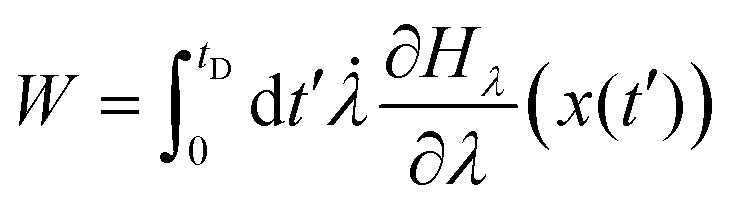 | (14) |
![[small lambda, Greek, dot above]](https://www.rsc.org/images/entities/char_e152.gif) = dλ/dt. The stochastic phase-space trajectory x(t) of the bead is determined here by solving the Langevin eqn (3). In the model system considered here, the only component of the system's energy that depends on the external driving parameter λ (=xOT), is the potential energy of the trap, UOT. As a result, ∂Hλ/∂λ = ∂UOT/∂xOT, and
= dλ/dt. The stochastic phase-space trajectory x(t) of the bead is determined here by solving the Langevin eqn (3). In the model system considered here, the only component of the system's energy that depends on the external driving parameter λ (=xOT), is the potential energy of the trap, UOT. As a result, ∂Hλ/∂λ = ∂UOT/∂xOT, and ![[small lambda, Greek, dot above]](https://www.rsc.org/images/entities/i_char_e152.gif) = dxOT(t)/dt = vOT. From eqn (2), for x ≥ xlbOT, since
= dxOT(t)/dt = vOT. From eqn (2), for x ≥ xlbOT, since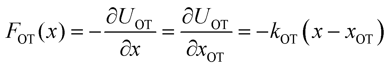 | (15) |
 | (16) |
Eqn (15) and (16) are used here to calculate the work done on the bead when the optical trap is translated from xOT = 0 to xOT = xfinalOT, at all times t at which the bead's location satisfies x(t) ≥ xlbOT. At other times, when the force of the optical trap on the bead is zero, the contribution to the work is zero. At any time t during the course of the Langevin simulation, the accumulated work until time t is calculated by numerically evaluating the integral in eqn (16) from t′ = 0 to t′ = t. Since the typical time steps used in the simulation are very small (Δt = 10−4 to Δt = 10−3), a simple rectangular method was used to carry out the quadrature, where at each time step, the accumulated work at the end of the previous time step is augmented by the product of the value of the integrand at the beginning of the time step with Δt.
2.5 Analytical evaluation of the free energy
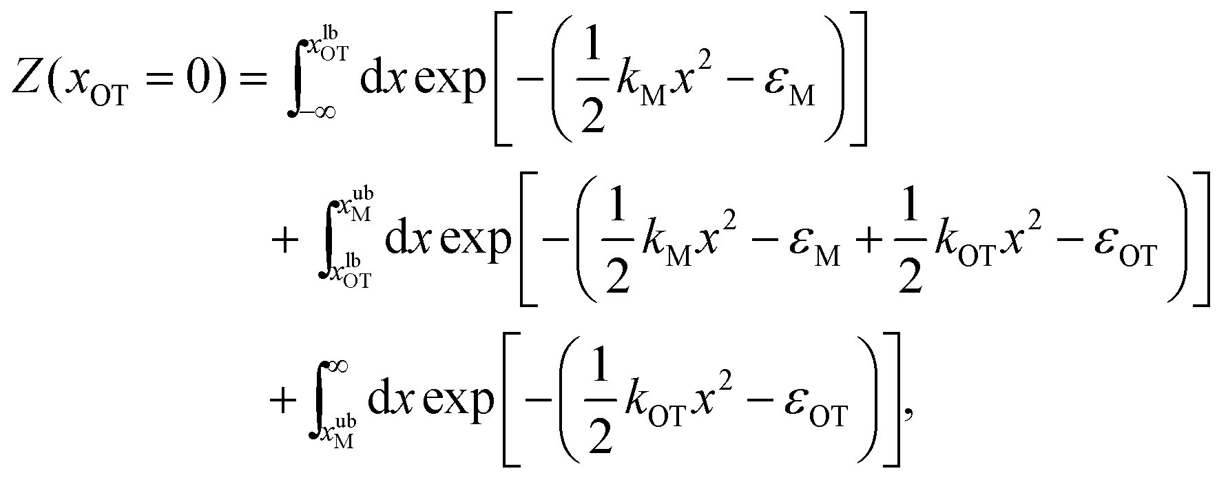
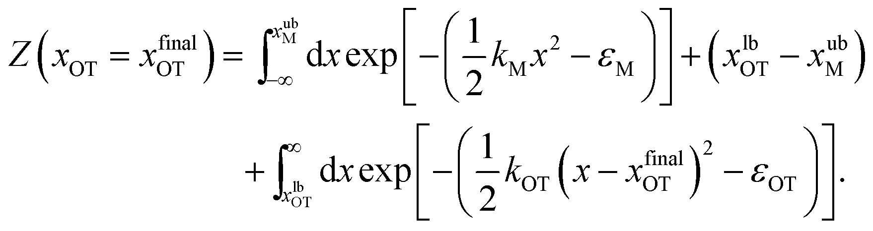
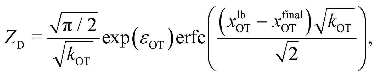
For the simple model considered here, the free energy difference between the initial and final states can be evaluated analytically exactly, and is given by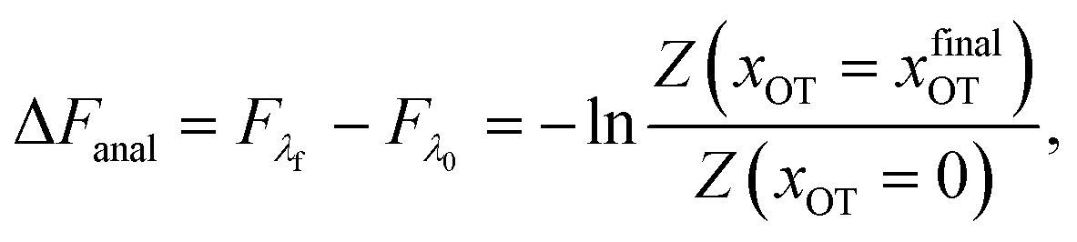 | (17) |
 | (18) |
 | (19) |
The bounds on the integrals in the expressions above can be understood from the schematic representations of the potentials in Fig. 1 and 2.
These integrals can be evaluated analytically, and give rise to the following expressions for the partition functions of the initial and final states, respectively,
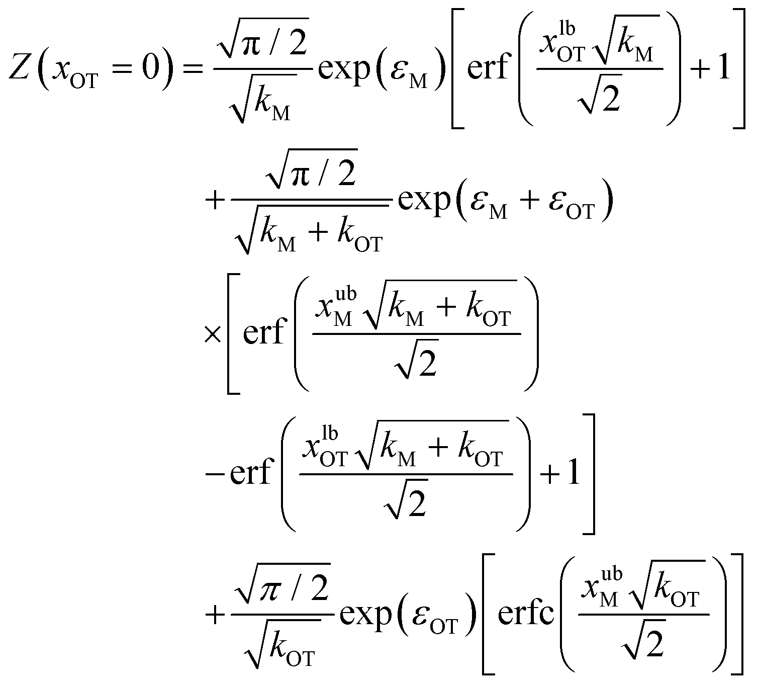 | (20) |
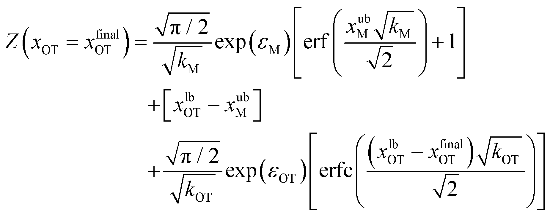 | (21) |
Eqn (20) and (21) can be used along with eqn (17) to obtain the exact value of the free energy difference between the initial and final state for any choice of parameter values in the potentials UM(x) and UOT(x). Free energy differences for the particular choice of values listed in Table 1 as parameter sets 1, 2 and 3, are given in Table 2. They are used to evaluate the accuracy of the free energy differences predicted by the Crooks and Jarzynski fluctuation theorems.
| v OT | Crooks | Jarzynski (forward) | Cumulants | |||
|---|---|---|---|---|---|---|
| ΔF | %Error | ΔF | %Error | ΔF6 | %Error | |
| Parameter set 1: ΔFanal = 1.796 | ||||||
| 0.01 | 1.80 ± 0.02 | 0.22 | 1.7955 ± 0.0002 | 0.03 | 1.796 | 0.03 |
| 0.05 | 1.79 ± 0.02 | 0.34 | 1.796 ± 0.001 | 0.004 | 1.799 | 0.14 |
| 0.1 | 1.80 ± 0.03 | 0.22 | 1.796 ± 0.002 | 0.03 | 1.797 | 0.06 |
| 0.5 | 1.76 ± 0.05 | 2.01 | 1.808 ± 0.016 | 0.65 | 1.823 | 1.48 |
| 1 | 1.81 ± 0.05 | 0.78 | 1.834 ± 0.044 | 2.12 | 1.746 | 2.81 |
| Parameter set 2: ΔFanal = 7.960 | ||||||
| 0.01 | 7.96 ± 0.04 | 0.004 | 7.9600 ± 0.0005 | 0.003 | 7.961 | 0.01 |
| 0.05 | 7.96 ± 0.05 | 0.004 | 7.960 ± 0.001 | 0.01 | 7.964 | 0.05 |
| 0.1 | 7.96 ± 0.04 | 0.004 | 7.962 ± 0.002 | 0.02 | 7.951 | 0.12 |
| 0.5 | 7.88 ± 0.09 | 1.01 | 7.974 ± 0.023 | 0.17 | 8.019 | 0.74 |
| 1 | 7.96 ± 0.09 | 0.004 | 8.165 ± 0.035 | 2.57 | 8.213 | 3.18 |
| Parameter set 3: ΔFanal = 0.934 | ||||||
| 0.01 | 0.94 ± 0.02 | 0.69 | 0.9333 ± 0.0002 | 0.02 | 0.933 | 0.05 |
| 0.05 | 0.94 ± 0.03 | 0.69 | 0.934 ± 0.001 | 0.03 | 0.937 | 0.34 |
| 0.1 | 0.93 ± 0.04 | 0.38 | 0.933 ± 0.001 | 0.02 | 0.933 | 0.08 |
| 0.5 | 0.93 ± 0.04 | 0.38 | 0.936 ± 0.012 | 0.21 | 0.955 | 2.25 |
| 1 | 0.94 ± 0.06 | 0.69 | 0.933 ± 0.020 | 0.03 | 1.063 | 13.91 |
3 Results and discussion
3.1 Code validation
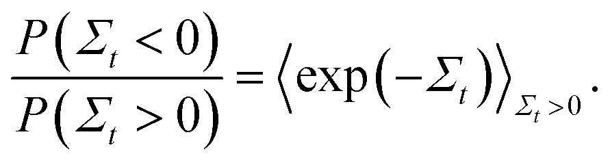
In order to validate the predictions of the current algorithm, comparisons were carried out with the results of two earlier studies which demonstrated the Evans–Searles fluctuation theorems using experiments and simulations involving an optical trap.37,49 The transient fluctuation theorem (TFT) of Evans and Searles25,50,51 states that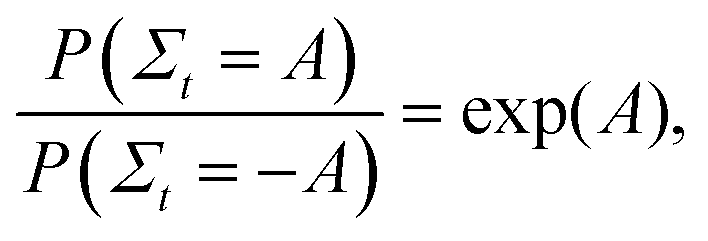 | (22) |
 | (23) |
In the first study considered here, Wang et al.37 examined the trajectory of a colloidal particle captured in an optical trap translated at a uniform velocity relative to the surrounding medium. They experimentally demonstrated the validity of the ITFT, and also carried out molecular dynamics simulations to show that the predictions of both the TFT and the ITFT were correct. In the second study, Carberry et al.49 observed the time-dependent relaxation of a colloidal particle subjected to a step change in the strength of a stationary optical trap. In this case, they were able to experimentally demonstrate the validity of both the TFT and the ITFT.
We have carried out Langevin simulations of these two previously studied applications of the Evans–Searles fluctuation theorems in order to ensure that our algorithm was implemented correctly. In both these examples, only a single optical trap is involved. As a consequence, the external force (in eqn (3)) on the colloidal particle due to the optical trap is given by,
| Fext(t) = −kOT(x(t) − xOT(t)) | (24) |
Study 1 (Wang et al.37):
Study 2 (Carberry et al.49):
The Langevin simulation of both these cases was carried out with 2 × 10⁶ trajectories, using a time step of 10−4. In both cases, after an initial equilibration time of 104 time steps, the distribution of particle positions was checked to see if the respective equilibrium distribution functions were obeyed. In Study 1, after equilibration, the optical trap was translated with a constant velocity vOT = 0.5, from time t = 0 to t = 10, with a constant trap strength kOT = 1. In Study 2, after equilibration, the optical trap strength was changed discontinuously from k0 = 1 to k1 = 2 at time t = 0, and the simulation continued until t = 10. The position of the colloidal particle at time t = 0 is taken to be x(0). Fig. 4 and 5 summarise the results of the validation studies.
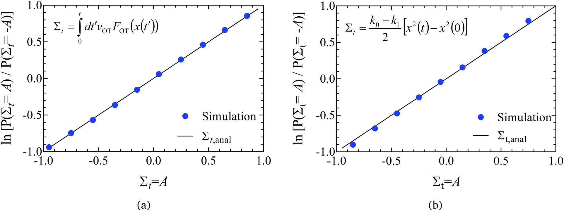 | ||
| Fig. 4 Validation of code through demonstration of the Evans–Searles transient fluctuation theorem. Natural log of the number ratio of trajectories with entropy production Σt to those with entropy production −Σtversus Σt (filled circles), found from 2 × 10⁶ trajectories. Lines are drawn with slope of 1 as predicted by the TFT (indicated as Σt,anal in the figure legend). (a) Study 1 (Wang et al.37). A line of best fit through simulation data has a slope 1.007 ± 0.004. (b) Study 2 (Carberry et al.49). A line of best fit through simulation data has a slope 1.058 ± 0.002. | ||
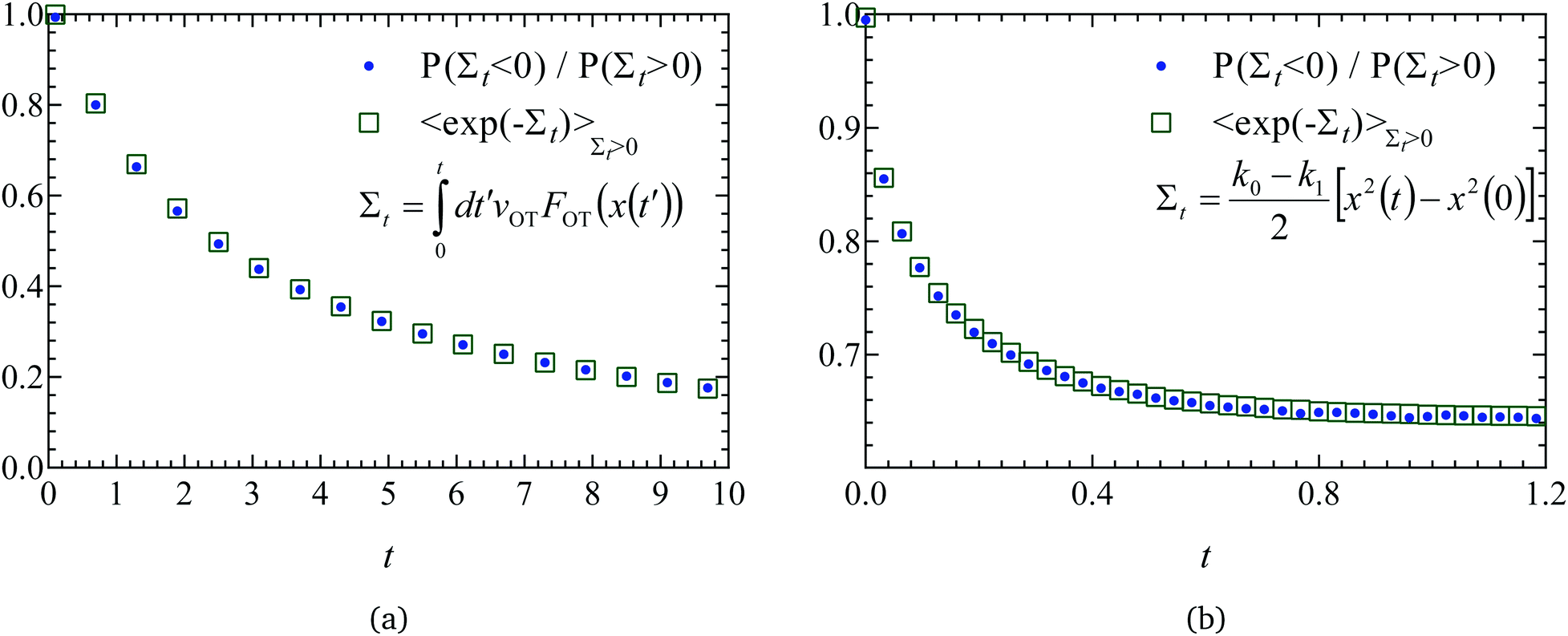 | ||
| Fig. 5 Validation of code through demonstration of the Evans–Searles integrated fluctuation theorem. The number ratio of entropy consuming (Σt < 0) trajectories to entropy producing (Σt > 0) trajectories (filled circles), and the entropy production averaged over entropy producing trajectories, 〈exp(−Σt)〉Σt>0 (empty squares), versus time, found from 2 × 10⁶ trajectories. (a) Study 1 (Wang et al.37). (b) Study 2 (Carberry et al.49). | ||
In order to demonstrate the TFT a histogram of the values of the dissipation function Σt at the end of the simulation was constructed over the 2 × 10⁶ trajectories. If Ni is the number of trajectories with dissipation function between Σt,i ± Δ/2 (where Δ = 0.1 is the size of the histogram bin, and Σt,i = iΔ), then the ratio of probabilities on the left hand side of eqn (22) can be evaluated from (Ni/N−i). Fig. 4(a) and (b) show the natural log of the ratio of the probabilities obtained in this manner for both the studies, plotted against the value of Σt. Also shown in the figures is a line of slope unity, which represents the prediction of the TFT.
The ITFT is demonstrated for the two studies in Fig. 5(a) and (b), respectively, by plotting the ratio of the number of entropy consuming trajectories (Σt < 0) to the number of entropy producing (Σt > 0) trajectories as a function of time, along with the time dependence of the entropy production averaged over the subset of 2 × 10⁶ trajectories in which entropy is produced.
3.2 Crooks fluctuation theorem
Simulations were carried out with the three sets of parameter values listed in Table 1 for the membrane and optical trap potentials, with a time step size Δt = 10−3. Rather than running the simulations for an initial equilibration period, the positions of the bead at time t = 0 were chosen such that they satisfied the known initial equilibrium distribution functions. Two kinds of simulations were carried out. The first kind, that generated forward trajectories, started at time t = 0 with the optical trap minimum at xOT = 0, followed by the trap minimum being translated with a uniform velocity vOT until it was located at xfinalOT at time t = tD. The set of optical trap velocities vOT = {0.01, 0.05, 0.1, 0.5, 1} was used. Note that tD depends on the value of vOT since the location xfinalOT is fixed and the same for all simulations. The second set of simulations, which generated reverse trajectories, started at time t = 0 with the optical trap minimum at xOT = xfinalOT, followed by the trap minimum being translated with the same set of velocities (but with opposite sign), until the minimum was located at xOT = 0 at time t = tD. Each simulation in the forward and reverse direction consisted of 105 trajectories. Ten such simulations were carried out in each case. The work values obtained after each trajectory in both sets of forward and reverse simulations (calculated using eqn (16)), were sorted into bins of width equal to 0.01. The distributions of work values obtained in this manner are plotted in Fig. 6 for the various cases. | ||
| Fig. 6 Evaluation of the equilibrium free energy using the Crooks fluctuation theorem for the three sets of potential parameter values listed in Table 1. In panel A, the probability of work W being performed in the forward path (PF(W)) is plotted alongside the distribution of work values in the reverse path (PR(W)) for parameter set 1, for the trap velocities vOT = {0.01, 0.05, 0.1, 0.5, 1}. In panels B (parameter set 1), C (parameter set 2), and D (parameter set 3), PF(W) is plotted alongside PR(−W). Note that the equilibrium free energy ΔF = W*, where W* is the value of work at which PF(W*) = PR(−W*) (indicated by the dotted vertical lines in panels B–D). | ||
Panel A in Fig. 6 plots, for parameter set 1, the probability of work W being performed in the forward path (PF(W)) alongside the distribution of work values in the reverse path (PR(W)) for the various trap velocities vOT indicated in the figure legend. While the work is predominantly positive in the forward trajectories (with a positive mean value), the work is predominantly negative in the reverse trajectories (with a negative mean value). The widening of the distributions with increasing trap velocities is also apparent. As noted previously, in the limit of a quasistatic process (vOT→0), PF(W)→δ(W − ΔF), and 〈W〉F = ΔF. However, for increasing values of vOT, the mean value shifts towards the right with a wider range of work values, and with 〈W〉F ≥ ΔF.
The usefulness of Crooks fluctuation theorem is best appreciated when PF(W) is plotted alongside PR(−W) as shown in panels B, C and D of Fig. 6. These three figure panels correspond to the three potential parameter sets listed in Table 1, respectively. As noted before, according to eqn (7), the value of work W* at which PF(W*) = PR(−W*) is nothing but the equilibrium free energy difference. Consequently, ΔF is estimated from Fig. 6 by finding the point of intersection of the forward and reverse probability curves for each of the trap velocities, for the three sets of parameter values. The values of ΔF obtained in this way are listed in Table 2, along with an estimate of the error in finding the point of intersection due to the relatively coarse interval used for binning the work values. The percentage relative error in the free energy predicted by the Crooks fluctuation theorem, defined by the expression
 | (25) |
The increase in error with increasing trap velocity can be understood by considering panel B in Fig. 6. As the velocity increases, it causes the mean value of work to shift away from the free energy value, with a simultaneous increase in the standard derivation of the distribution. As a result, the crossover occurs at the tails of the distributions, where errors are high and therefore require much larger populations to ensure adequate statistics. Fig. 6 indicates that the velocities at which this could become an issue is sensitive to the choice of potential parameters. Parameter set 1 (panel B), where the optical trap strength was double that of the membrane, and the barrier height for detachment was much lower than that of re-attachment (see Fig. 3a), seems to have the most movement of the mean away from the exact free energy value. On the other hand parameter set 3 (panel D), where barrier heights are of (kBT) (see Fig. 3c), seems to be the least affected by increased velocity.
3.3 Jarzynski equality
The form of the Jarzynski equality given by eqn (8) corresponds to switching the system from an initial equilibrium state with λ = λ0 to a final state with λ = λf. When the system is switched from an initial equilibrium state with λ = λf to a final state with λ = λ0, the Jarzynski equality takes the form,52| 〈e−W〉R = eΔF | (26) |
The sets of forward and reverse simulations carried out to demonstrate the Crooks fluctuation theorem can also be used to examine the usefulness of the Jarzynski equality. The ensemble averages on the left hand sides of eqn (8) and (26) were calculated using the values of work accumulated at the end of each of the 105 trajectories corresponding to a particular simulation. The sets of forward and reverse simulations were repeated ten times each, so that we obtain ten estimates for the equilibrium free energy in each case, and the errors can be estimated. The mean of these 10 values, and the standard error in these mean values are displayed in Fig. 7 for all the cases considered here. Parameter sets 1, 2, and 3 are shown in rows 1, 2, and 3 respectively, with the left hand column showing results for the forward trajectories whilst the right hand column shows results for reverse trajectories. The mean value of ΔF and the standard error in the mean are also compared with exact analytical values in Table 2 for simulations carried out in the forward direction. Note that the percentage relative error reported in the table is calculated using eqn (25) with the mean value of ΔF.
 | ||
| Fig. 7 Free energy values estimated using Jarzynski's equality as a function of trap velocity vOT. Symbols are results of simulations, while the dashed lines indicate the exact analytical value of the free energy, for parameter sets 1 (row 1), 2 (row 2) and 3 (row 3). Results for the forward trajectories are displayed in column one, whilst reverse trajectories are displayed in column two. Error bars indicate the standard error in the estimated mean free energy values obtained from ten repeated simulations. | ||
A feature of all approaches for determining free energy differences using ensemble averages, of which the Jarzynski equality is no exception, is their limitation due to sample size. As argued by Jarzynski,28 for systems where the spread in the distributions PF(W) and PR(W) is large, the function exp(−W) varies significantly over many standard deviations about the mean value of work. As a result, the numerically determined average 〈exp(−W)〉 can be dominated by work values that are by their very nature statistically rare. Therefore an unreasonable number of measurements of the work would be required to get an accurate result. This results in a practical restriction on the rates at which the system can be switched between λ0 and λf. As can be seen from Fig. 7 and Table 2, the accuracy in the estimation of the free energy decreases with the trap velocity in all cases.
A comparison of the relative errors in the free energies predicted by the Crooks fluctuation theorem and the Jarzynski equality (in the case of forward trajectories) in Table 2 shows that they are roughly similar in magnitude for the various cases. As noted earlier, there is a reduction in accuracy with increasing trap velocity, which appears to be magnified when either one or both the potential well depths are high compared to kBT, which is the case for parameter sets 1 and 2 (displayed in Fig. 3). The dependence of the error on well depth is studied shortly below.
For slow rates of switching between λ0 and λf, the distributions PF(W) and PR(W) are expected to be approximately Gaussian.52 In this case, retaining only the first two terms in the cumulant expansion for 〈exp(−W)〉 (which is discussed in greater detail in the section below), one can write,52
where σF2 and σR2 are the variances of the work distributions PF(W) and PR(W), respectively. Defining the mean dissipated work 〈Wd〉 as the difference between the mean actual work of the process and the reversible work (which is equal to the equilibrium free energy), we can estimate the departure from the Gaussian approximation by evaluating the error estimates EF and ER defined by,
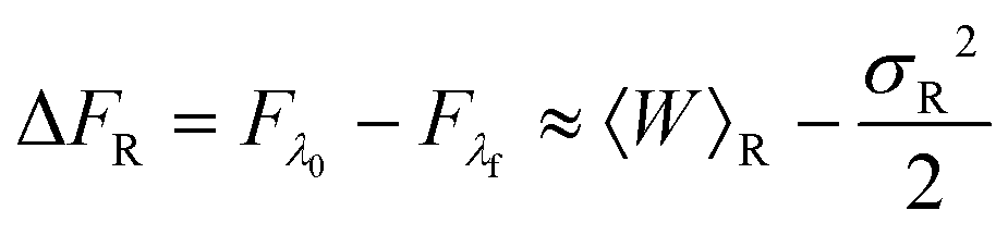
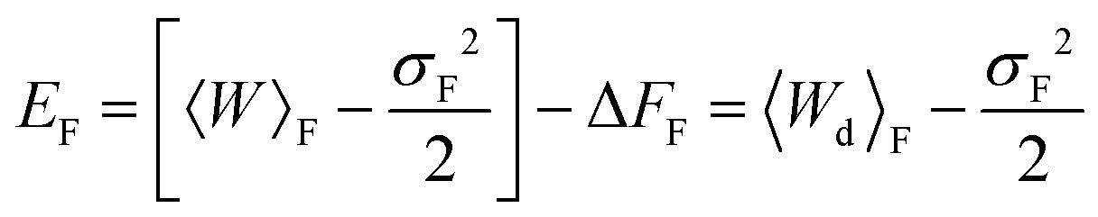 | (27) |
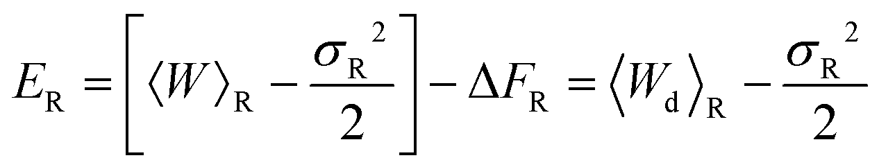 | (28) |
The values of mean actual work, variances, mean dissipated work and error estimates, for membrane and optical trap potential parameters corresponding to set 1, are displayed in Table 3 for both the forward and reverse paths. Clearly, the Gaussian approximation leads to an error of less than 9% up to trap velocities vOT = 0.5. Interestingly, the variances of PF(W) and PR(W) and the mean dissipated work in the forward and reverse paths are roughly equal in magnitude for identical velocities in the forward and reverse paths.
| v OT | ΔFF | 〈W〉F | σ F 2 | 〈Wd〉F | E F |
|---|---|---|---|---|---|
| Forward trajectories | |||||
| 0.01 | 1.796 | 1.860 | 0.128 | 0.064 | 0.000 |
| 0.05 | 2.116 | 0.632 | 0.320 | 0.003 | |
| 0.1 | 2.428 | 1.262 | 0.632 | 0.001 | |
| 0.5 | 4.842 | 5.922 | 3.046 | 0.085 | |
| 1 | 7.535 | 10.604 | 5.739 | 0.437 | |
| v OT | ΔFR | 〈W〉R | σ R 2 | 〈Wd〉R | E R |
|---|---|---|---|---|---|
| Reverse trajectories | |||||
| 0.01 | −1.796 | −1.732 | 0.128 | 0.064 | 0.000 |
| 0.05 | −1.481 | 0.633 | 0.315 | 0.001 | |
| 0.1 | −1.159 | 1.281 | 0.637 | 0.003 | |
| 0.5 | 1.320 | 6.337 | 3.116 | 0.052 | |
| 1 | 4.258 | 12.552 | 6.054 | 0.222 | |
For distributions that are not Gaussian, the exponential average in Jarzynski's equality can be expanded in terms of cumulants,52 and the convergence of ΔF can be studied as a function of the various potential parameters, as discussed in the section below. It is worth noting that it is also possible to obtain estimates for the free energy that are accurate to a higher order in the cumulant expansion than the Gaussian approximation by suitably combining the mean work and variance in the forward and reverse paths.52
3.4 Cumulant expansion for the free energy of binding
The average of the exponential of work on the left hand sides of eqn (8) and (26) in Jarzynski's equality can be expanded in terms of cumulants.52 In the case of forward paths, this leads to the following expression for the free energy change: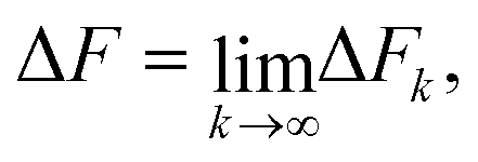 | (29) |
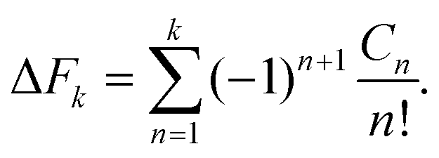 | (30) |
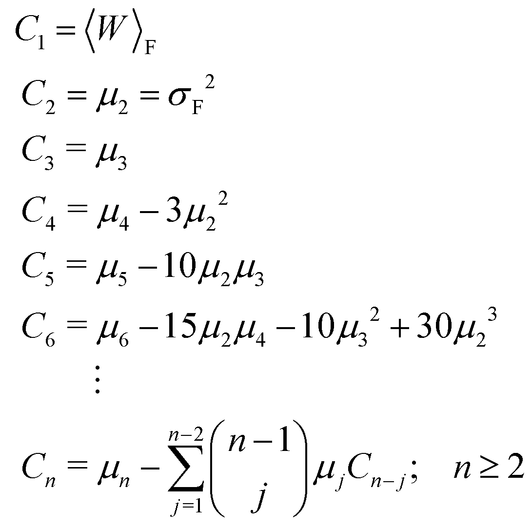 | (31) |
| μn = 〈[W − 〈W〉F]n〉F. | (32) |
The recursive relationship between the cumulants and central moments in eqn (31) has been given by Smith.53 In the case of reverse paths, the cumulant expansion on the right hand side of eqn (30) leads to the free energy change −ΔF = Fλ0 − Fλf, with μn in the expressions for Cn being the central moments of PR(W).
An analysis of the simulation results for the forward and reverse paths in terms of the cumulant expansion is displayed in Fig. 8, where the difference between the values of ΔFk (which represent the approximate estimate of the free energy change given by k terms of the cumulant expansion) and the analytical value ΔFanal, is plotted against the trap velocities vOT (for values of k in the range 2 ≤ k ≤ 6). Additionally, the particular values obtained for ΔF6 in the case of forward trajectories, and the relative error compared to the exact values are listed in Table 2. As expected, at low trap velocities where the system approaches a quasistatic process, the work distribution approaches a Gaussian, and quite accurate results are obtained with two cumulants. However as the trap velocity increases, higher cumulant numbers are required until, for vOT = 1, even at cumulant numbers of 6 the system has still not converged.
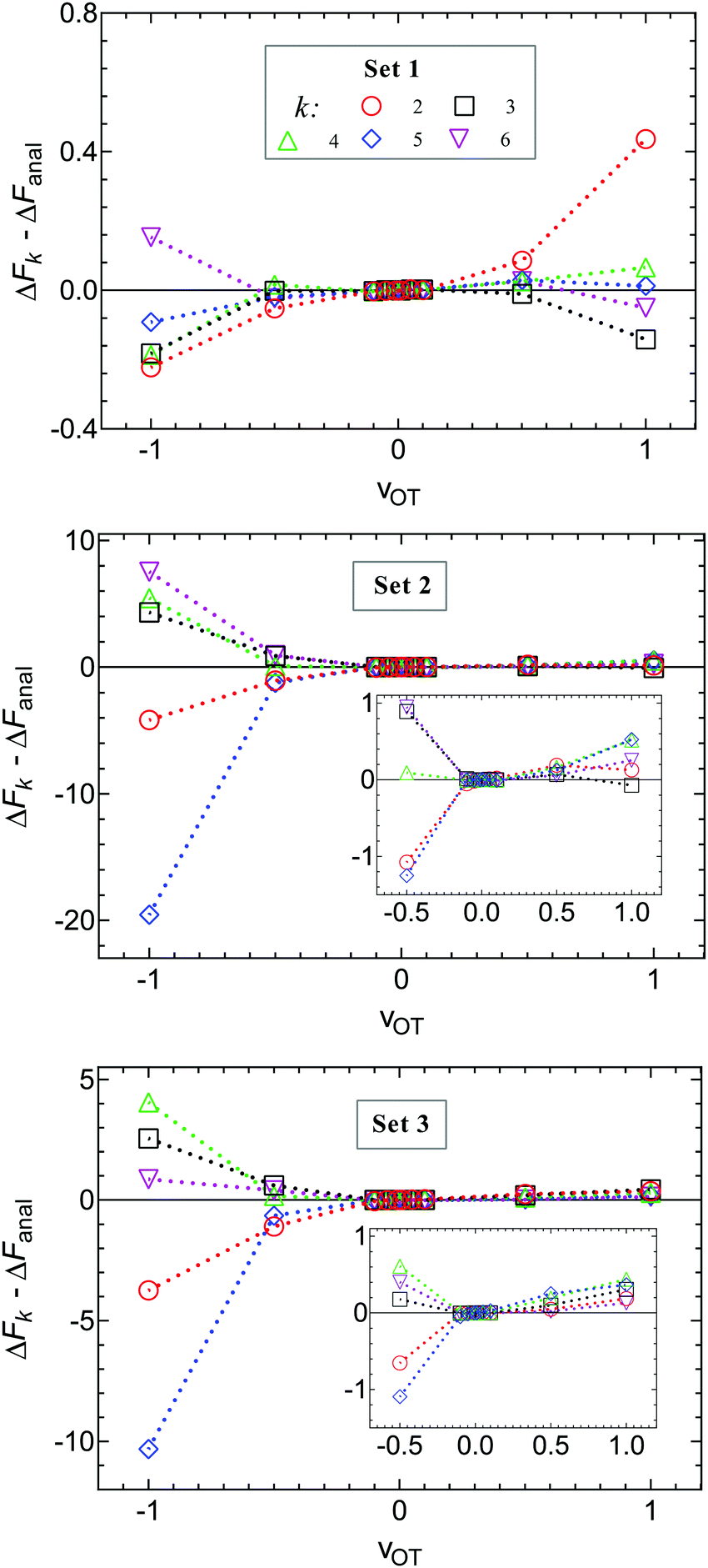 | ||
| Fig. 8 Deviation of the approximate estimate of the free energy change ΔFk, obtained from a cumulant expansion, from the analytical free energy ΔFanal, at various values of trap velocity vOT, for different numbers of terms k in the expansion. Symbols are results of simulations for parameter sets 1 (row 1), 2 (row 2) and 3 (row 3). Lines are drawn to guide the eye. Data for the forward trajectories and reverse trajectories are displayed together by representing the velocities in the latter case with negative values. The insets for sets 2 and 3 make it easier to identify the values of ΔFk − ΔFanal for all values of vOT ≠ −1. | ||
An alternative representation of the cumulant expansion data is given in Fig. 9, where ΔFk − ΔFanal is plotted as a function of k (2 ≤ k ≤ 6), at the lowest and highest trap velocities (vOT = 0.01 and vOT = 1.0), for parameter values corresponding to set 3. Since the cumulant expansion is an approximation for the left hand sides of eqn (8) and (26), we expect that the free energy difference ΔFk should converge to the free energy difference predicted by Jarzynski's equality ΔFJarzynski, for sufficiently large values of k. This can be seen to be clearly the case for vOT = 0.01, for both the forward and reverse trajectories, from the top row in Fig. 9, where the solid line corresponds to the difference ΔFJarzynski − ΔFanal. The scale of the y-axis in both the subfigures in the bottom row of Fig. 9 (corresponding to vOT = 1.0) makes it difficult to distinguish ΔFJarzynski − ΔFanal from 0. While the values of ΔFk − ΔFanal appear to be getting smaller with increasing k, there are still large changes in ΔFk with increasing k, and convergence has not occurred by k = 6, as was observed previously at this value of trap velocity in Fig. 8.
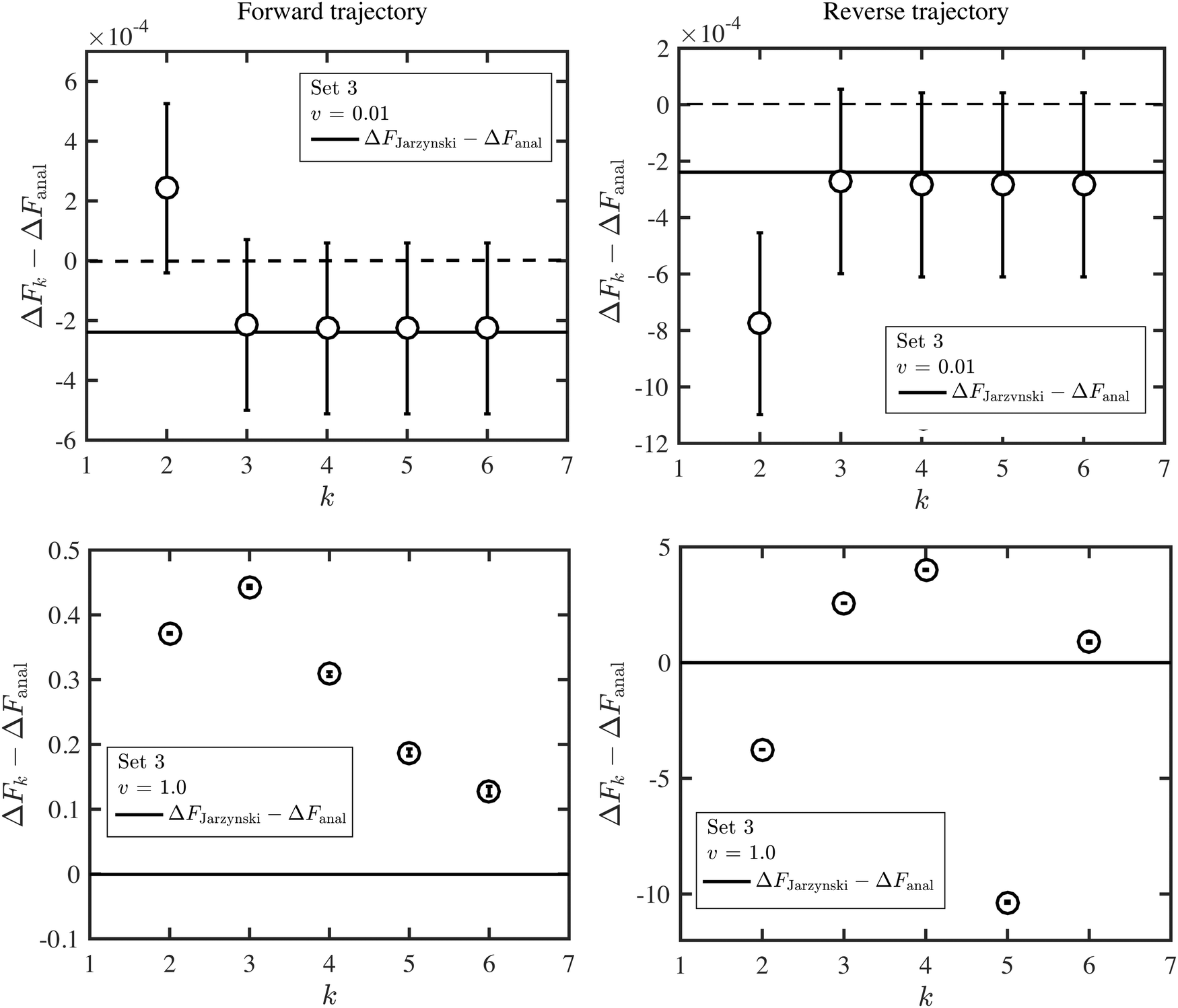 | ||
| Fig. 9 Deviation of the approximate estimate of the free energy change ΔFk, obtained from a cumulant expansion, from the analytical free energy ΔFanal, as a function of the numbers of terms k in the expansion, at two values of the trap velocity vOT, for parameter values corresponding to set 3. The full lines indicate the difference ΔFJarzynski − ΔFanal. Results for the forward trajectories are displayed in column one, whilst reverse trajectories are displayed in column two. | ||
The cumulant expansion can also be used to examine the influence of well depth. In order to do so, simulations in the forward direction were carried out for 106 trajectories with time step Δt = 10−4, for trap velocities vOT = {0.01, 0.05, 0.1, 0.5, 1}. In all cases, the final location of the trap potential minimum was xfinalOT = 6. The membrane potential depth was held fixed at εM = 4, whilst a parameter sweep from 1 to 8 was carried out for the optical trap potential depth, εOT. The trap strengths kM and kOT for both the membrane and the optical trap potentials were held constant at a value of two. Results of the cumulant analysis are plotted in Fig. 10 for the difference ΔFk − ΔFanal, as a function of trap velocity, at the various values of k, with each subfigure representing a different value of εOT. Since the exact analytical value ΔFanal is different for each value of trap well depth, the values are given in the caption to Fig. 10. The cumulant analysis suggests that convergence occurs quickly at the low velocities and becomes poorer and poorer at higher velocities. It is also evident that increasing optical trap well depth significantly increases the error in the estimate of the free energy for a given value of the number of terms k in the cumulant expansion (note the different scales of the y-axes in the different subfigures of Fig. 10).
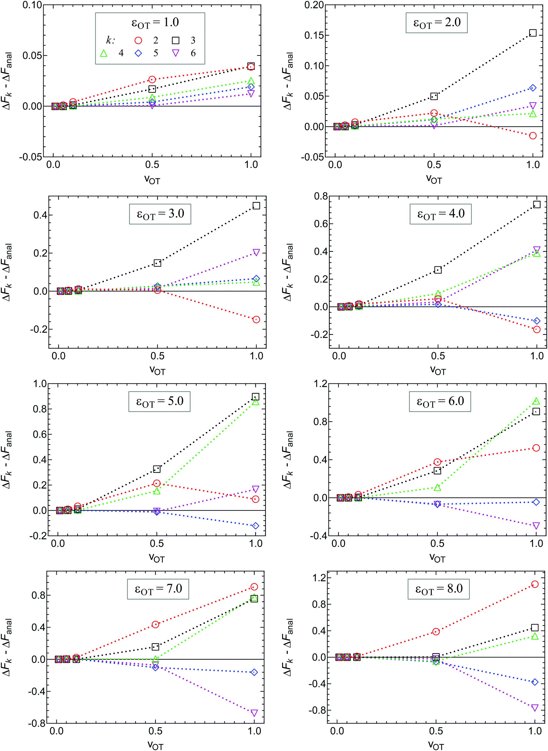 | ||
| Fig. 10 Influence of the optical trap well depth on ΔFk − ΔFanal, for 2 ≤ k ≤ 6, calculated at various values of trap velocity vOT. A parametric sweep was carried out from εOT = 1 (top left) to 8 (bottom right), whilst keeping all other potential parameters constant (εM = 4, kM = 2 and kOT = 2). The exact analytical values of the free energy for each of the optical trap depths were, (εOT, ΔFanal): (1.0, 0.599574), (2.0, 1.509950), (3.0, 2.327020), (4.0, 2.952370), (5.0, 3.336500), (6.0, 3.525130), (7.0, 3.604400), (8.0, 3.635160). | ||
3.5 Probabilities of attachment and detachment via umbrella sampling
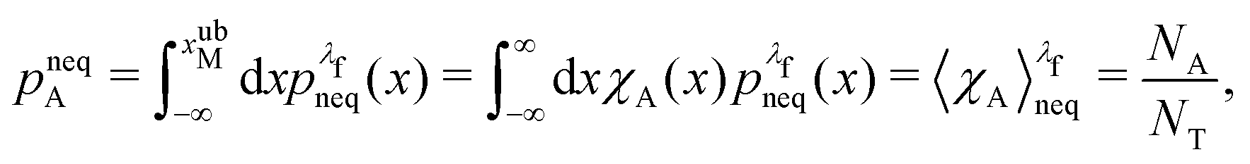
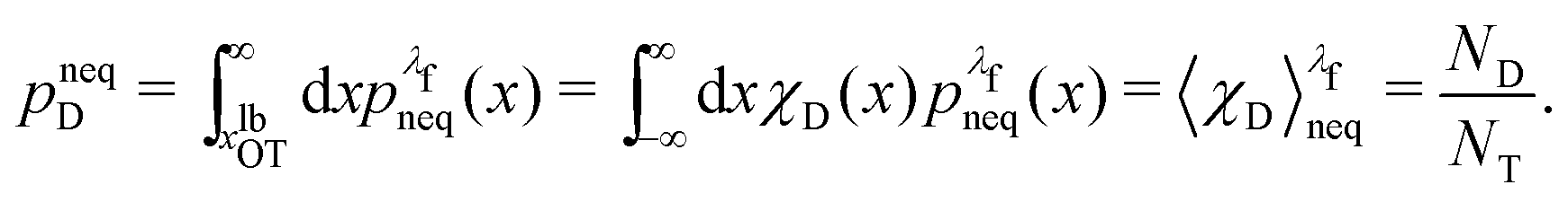
An important quantity that is frequently the focus of experiments on cell adhesion is the probability of adhesion. Measurements of the adhesion probability are often used to determine the kinetics of the adhesion process through the calculation of on and off-rates of binding etc. The experiments, which typically monitor whether a binding event occurs or not when ligand and receptor bearing surfaces are brought into contact, are by their very nature carried out at finite rates. As a result, a true measure of the equilibrium probability of binding is difficult to obtain. In this context, the method of non-equilibrium umbrella sampling31,36,54,55 provides a means of determining the equilibrium binding probability from non-equilibrium measurements. Here, we demonstrate how non-equilibrium umbrella sampling can be used to find, at the end of the unbinding experiment, the probability of either the bead being attached to the cell, or being detached from it and held in the optical trap.At the end of the computer experiment, when t = tD and the optical trap minimum is located at xfinalOT, it makes sense to sub-divide the x axis into three intervals (cf.Fig. 2(c)): First, there is the interval −∞ < x(tD) ≤ xubM, which we define as the set of states that correspond to the bead still being attached to the cell (membrane). The second interval is xubM < x(tD) < xlbOT, where the potential is flat, and which we define as corresponding to an intermediate state of the bead. Finally, the interval xlbOT ≤ x(tD) < ∞ corresponds, according to our definition, to the detached (or optically trapped) state of the bead. In what follows, we will focus on the equilibrium probabilities for the attached state and the detached state; the probability for the intermediate state then follows trivially by subtracting the sum of these values from one.
To formalise these definitions, it is useful to introduce the indicator functions χA and χD,
 | (33) |
 | (34) |
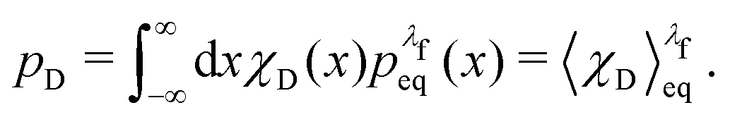
The equilibrium probabilities for the attached and the detached states are then simply the Boltzmann averages of χA and χD, respectively. Here of course the Boltzmann distribution corresponding to the final potential profile (λ = λf) must be used:
 | (35) |
 | (36) |
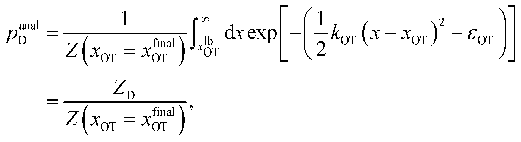
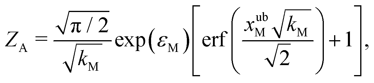
For the choice of potentials in the present work, it is straightforward to determine these values analytically. Using arguments along the lines of those in Section 2.5 for the analytical determination of free energy differences, we can show that
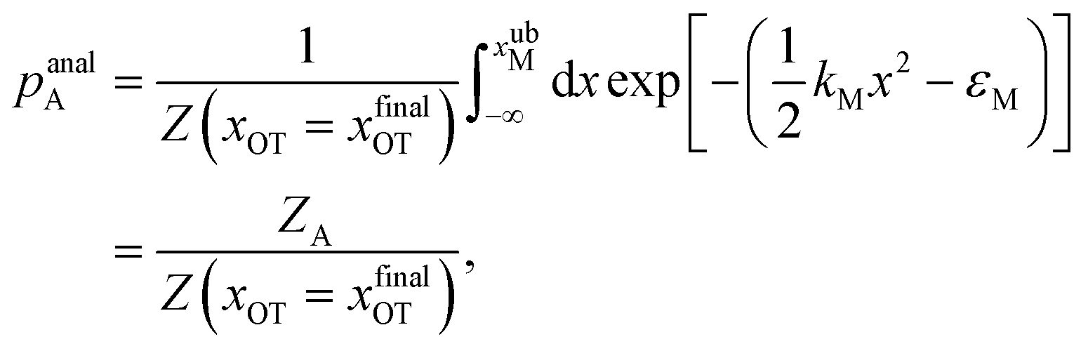 | (37) |
 | (38) |
 | (39) |
 | (40) |
We denote the total number of detachment simulations with NT. Similarly, NA denotes the number of runs where the bead ends up in the attached state (χA(x(t = tD)) = 1). Analogously, ND is the number of runs where the bead is finally detached. If 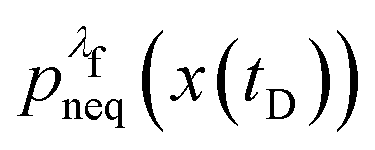 is the non-equilibrium distribution of bead positions at the final time tD, then the non-equilibrium probabilities of attachment and detachment, defined by the following expressions, are easily estimated by simulations from the ratios NA/NT and ND/NT, respectively:
 | (41) |
 | (42) |
We now use the technique of non-equilibrium umbrella sampling to obtain the equilibrium probabilities from the non-equilibrium simulations. Let us outline this method in general terms:
For an observable B that has been sampled by a non-equilibrium (computer) experiment, i.e., using the probability distribution  , we simply have to multiply each data point with the ratio
  such that the data point is given the weight
  rather than
  . It can be shown31,54,55 that the ratio
  is nothing but the factor e−W, except for normalisation. Therefore, the data need to be reweighted according to the formula
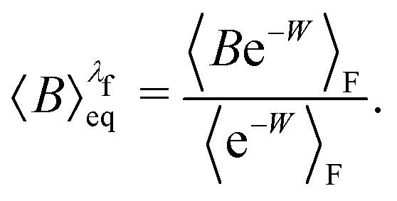 | (43) |
 | (44) |
 | (45) |
Simulation data generated previously for examining the influence of well depth in Section 3.4 has been used here for evaluating the usefulness of non-equilibrium umbrella sampling, for trap velocities vOT = {0.01, 0.05, 0.1, 0.5, 1}. The potential parameters used in the simulations are as given in the caption to Fig. 10, along with xfinalOT = 6.
The symbols in Fig. 11(a) and (b) are the non-equilibrium probabilities of attachment and detachment pneqA and pneqD, determined from eqn (41) and (42) for various trap velocities, while the symbols in Fig. 11(c) and (d) are the equilibrium probabilities pA and pD, determined by applying the umbrella sampling procedure as expressed in eqn (44) and (45). Error bars estimated from the ten repeated simulations are smaller than the symbol size in Fig. 11(c) and (d). The curves in the subfigures of Fig. 11 represent the analytical equilibrium probabilities panalA and panalD (as appropriate), calculated from eqn (37) and (38), respectively.
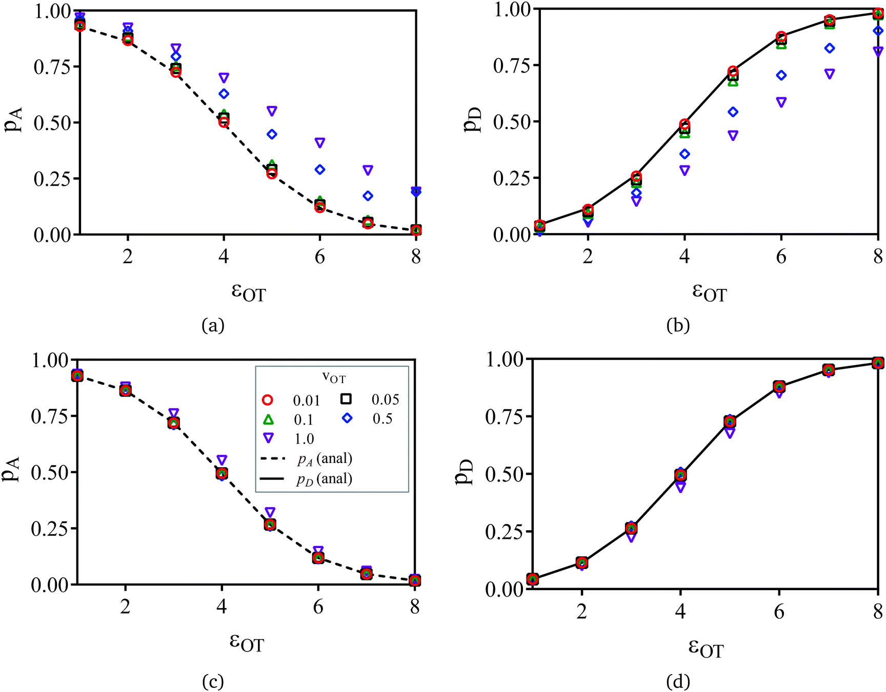 | ||
| Fig. 11 Probabilities of attachment and detachment as a function of optical trap well depth, at various values of trap velocity vOT = {0.01, 0.05, 0.1, 0.5, 1}. The optical trap well depth εOT was varied from 1 to 8, whilst keeping all other potential parameters constant (εM = 4, kM = 2 and kOT = 2). The symbols in (a) and (b) are the non-equilibrium probabilities of attachment and detachment pneqA and pneqD, while the symbols in (c) and (d) represent the equilibrium probabilities pA and pD obtained from non-equilibrium umbrella sampling. The curves in (a) to (d) are the analytical equilibrium probabilities panalA and panalD (as appropriate). | ||
As expected, Fig. 11(a) and (b) indicate that the non-equilibrium probabilities are nearly identical to the equilibrium probabilities at low trap velocities, but deviate from the latter more and more as the trap velocity increases. Interestingly, the greatest departure occurs for membrane and optical trap potential well depths that are roughly equal in magnitude. Not surprisingly, the probability of detachment is greatest for the largest optical trap well depth, while the likelihood of remaining in the membrane potential is high at low trap well depths. For nearly all the trap velocities, except perhaps at vOT = 1 (for roughly equal trap strengths), application of umbrella sampling recovers the equilibrium probabilities nearly perfectly.
4 Conclusions
A simple model for the detachment of a ligand coated bead with the help of an optical tweezer, from receptors on the surface of a cell to which it is bound, has been used to examine if fluctuation theorems are useful in determining equilibrium free energies, which in turn provide information about the binding energetics. By using truncated harmonic potentials to represent the stationary cell membrane and the moving optical trap, and a Langevin equation to model the stochastic motion of the bead in these potentials, the distribution of work performed in driving the system from an initial equilibrium state to a final non-equilibrium state (at various finite rates) has been calculated by carrying out repeated simulations of the Langevin equation in the forward and reverse directions. The former corresponds to the membrane and trap potentials being superposed at time t = 0, followed by the optical trap being translated uniformly until the two potentials are sufficiently apart at the final time t = tD. The latter refers to the opposite situation.The calculation of work distributions enables the determination of the equilibrium free energy change between the initial and final states of the system, using both the Crooks fluctuation theorem and the Jarzynski equality. The simplicity of the model also permits a straight forward determination of the exact free energy change by analytical means. It is found that both fluctuation theorems lead to excellent predictions provided the rate of switching from the initial to the final state is sufficiently slow. For relatively rapid rates of trap translation, sampling problems (for the given sample size) lead to a decrease in accuracy. The reduction in accuracy is discussed both in terms of a Gaussian approximation for the work distributions, and a cumulant expansion for the average of the exponential of work.
The method of non-equilibrium umbrella sampling has been used to determine the equilibrium probability that, after translating the trap from its initial to its final location, the bead and cell are still attached (i.e., the bead lies only within the range of influence of the membrane potential), and the equilibrium probability that the bead and cell have been detached (the bead lies only within the range of influence of the optical trap potential), for a range of different values of the optical trap well depth. It is seen that by appropriately analysing the non-equilibrium simulation data, accurate estimates of the equilibrium probabilities of attachment and detachment can be found for all but the highest rates of trap translation.
In conclusion, although a very simple model has been used, the present work demonstrates that non-equilibrium fluctuation theorems can be applied without significant statistical problems to binding/unbinding experiments carried out with optical trap velocities that are realizable under experimental conditions. Combined with the theoretical procedure outlined in Section 2.3, they could provide a reliable means of extracting unknown membrane potentials (see eqn (13)).
Acknowledgements
The authors gratefully acknowledge CPU time grants from the National Computational Infrastructure (NCI) facility hosted by the Australian National University, and Victorian Life Sciences Computation Initiative (VLSCI) hosted by the University of Melbourne. We thank C. Sasmal for help with preparation of some of the figures.References
- K. Kendall, M. Kendall and F. Rehfeldt, Adhesion of cells, viruses and nanoparticles, Springer Science & Business Media, 2010 Search PubMed.
- P. Bongrand, P. M. Claesson and A. S. Curtis, Studying cell adhesion, Springer Science & Business Media, 2013 Search PubMed.
- E. A. Evans and D. A. Calderwood, Science, 2007, 316, 1148–1153 CrossRef CAS PubMed.
- L. H. Miller, D. I. Baruch, K. Marsh and O. K. Doumbo, Nature, 2002, 415, 673–679 CrossRef CAS PubMed.
- G. D. Turner, H. Morrison, M. Jones, T. M. Davis, S. Looareesuwan, I. D. Buley, K. C. Gatter, C. I. Newbold, S. Pukritayakamee and B. Nagachinta, et al. , Am. J. Pathol., 1994, 145, 1057 CAS.
- J. A. Rowe, A. Claessens, R. A. Corrigan and M. Arman, Expert Rev. Mol. Med., 2009, 11, e16 CrossRef PubMed.
- S. Suresh, J. Spatz, J. Mills, A. Micoulet, M. Dao, C. Lim, M. Beil and T. Seufferlein, Acta Biomater., 2005, 1, 15–30 CrossRef CAS PubMed.
- J. P. Johnson, Cancer Metastasis Rev., 1999, 18, 345–357 CrossRef CAS PubMed.
- S. Hirohashi and Y. Kanai, Cancer Sci., 2003, 94, 575–581 CrossRef CAS.
- J. P. Thiery, C. R. Phys., 2003, 4, 289–304 CrossRef CAS.
- R. O. Hynes, Cell, 1992, 69, 11–25 CrossRef CAS PubMed.
- K. C. Neuman and A. Nagy, Nat. Methods, 2008, 5, 491 CrossRef CAS PubMed.
- X. Zhang, E. Wojcikiewicz and V. T. Moy, Biophys. J., 2002, 83, 2270–2279 CrossRef CAS PubMed.
- M. Benoit, D. Gabriel, G. Gerisch and H. E. Gaub, Nat. Cell Biol., 2000, 2, 313–317 CrossRef CAS PubMed.
- J. Zlatanova, S. M. Lindsay and S. H. Leuba, Prog. Biophys. Mol. Biol., 2000, 74, 37–61 CrossRef CAS PubMed.
- P.-H. Puech, K. Poole, D. Knebel and D. J. Muller, Ultramicroscopy, 2006, 106, 637–644 CrossRef CAS PubMed.
- A. Noy, Handbook of molecular force spectroscopy, Springer Science & Business Media, 2007 Search PubMed.
- S. E. Chesla, P. Selvaraj and C. Zhu, Biophys. J., 1998, 75, 1553–1572 CrossRef CAS PubMed.
- J.-Y. Shao, G. Xu and P. Guo, Front. Biosci., 2004, 9, 2183–2191 CrossRef CAS.
- H. Zhao, X. Dong, X. Wang, X. Li, F. Zhuang, J. Stoltz and J. Lou, Microvasc. Res., 2002, 63, 218–226 CrossRef CAS PubMed.
- J. Dobson, Nat. Nanotechnol., 2008, 3, 139–143 CrossRef CAS PubMed.
- A. J. Crick, M. Theron, T. Tiffert, V. L. Lew, P. Cicuta and J. C. Rayner, Biophys. J., 2014, 107, 846–853 CrossRef CAS PubMed.
- D. G. Grier, Nature, 2003, 424, 810–816 CrossRef CAS PubMed.
- E. Fällman, S. Schedin, J. Jass, M. Andersson, B. E. Uhlin and O. Axner, Biosens. Bioelectron., 2004, 19, 1429–1437 CrossRef PubMed.
- D. J. Evans and D. J. Searles, Adv. Phys., 2002, 51, 1529–1585 CrossRef.
- U. Seifert, Rep. Prog. Phys., 2012, 75, 126001 CrossRef PubMed.
- C. Jarzynski, Phys. Rev. Lett., 1997, 78, 2690 CrossRef CAS.
- C. Jarzynski, Phys. Rev. E: Stat. Phys., Plasmas, Fluids, Relat. Interdiscip. Top., 1997, 56, 5018 CrossRef CAS.
- G. E. Crooks, J. Stat. Phys., 1998, 90, 1481–1487 CrossRef.
- G. E. Crooks, Phys. Rev. E: Stat. Phys., Plasmas, Fluids, Relat. Interdiscip. Top., 1999, 60, 2721 CrossRef CAS.
- G. E. Crooks, Phys. Rev. E: Stat. Phys., Plasmas, Fluids, Relat. Interdiscip. Top., 2000, 61, 2631 CrossRef.
- R. B. Sandberg, M. Banchelli, C. Guardiani, S. Menichetti, G. Caminati and P. Procacci, J. Chem. Theory Comput., 2015, 11, 423–435 CrossRef CAS PubMed.
- V. Gapsys, S. Michielssens, J. H. Peters, B. L. de Groot and H. Leonov, Molecular modeling of proteins, Springer, 2015, pp. 173–209 Search PubMed.
- D. Carberry, J. C. Reid, G. Wang, E. M. Sevick, D. J. Searles and D. J. Evans, Phys. Rev. Lett., 2004, 92, 140601 CrossRef CAS PubMed.
- C. Bustamante, Q. Rev. Biophys., 2005, 38, 291–301 CrossRef CAS PubMed.
- Y. Gao, G. Wang, D. Williams, S. R. Williams, D. J. Evans and E. Sevick, J. Chem. Phys., 2012, 136, 054902 CrossRef CAS PubMed.
- G. Wang, E. M. Sevick, E. Mittag, D. J. Searles and D. J. Evans, Phys. Rev. Lett., 2002, 89, 050601 CrossRef CAS PubMed.
- E. Sackmann and S. Gönnenwein, Prog. Theor. Phys. Suppl., 2006, 165, 78–99 CrossRef CAS.
- G. I. Bell, M. Dembo and P. Bongrand, Biophys. J., 1984, 45, 1051 CrossRef CAS PubMed.
- S. Gönnenwein, PhD thesis, Technische Universität München, 2003.
- D. Boal and D. H. Boal, Mechanics of the cell, Cambridge University Press, 2012 Search PubMed.
- E. Sackmann and A.-S. Smith, Soft Matter, 2014, 10, 1644–1659 RSC.
- E. Hodges, PhD thesis, Monash University, 2016, submitted.
- M. Fried, F. Nosten, A. Brockman, B. J. Brabin and P. E. Duffy, Nature, 1998, 395, 851–852 CrossRef CAS.
- J. G. Beeson, S. J. Rogerson, B. M. Cooke, J. C. Reeder, W. Chai, A. M. Lawson, M. E. Molyneux and G. V. Brown, Nat. Med., 2000, 6, 86–90 CrossRef CAS PubMed.
- C. F. Ockenhouse, M. Ho, N. N. Tandon, G. A. Van Seventer, S. Shaw, N. J. White, G. Jamieson, J. D. Chulay and H. K. Webster, J. Infect. Dis., 1991, 164, 163–169 CrossRef CAS PubMed.
- F. K. Glenister, R. L. Coppel, A. F. Cowman, N. Mohandas and B. M. Cooke, Blood, 2002, 99, 1060–1063 CrossRef CAS PubMed.
- B. M. Cooke, F. K. Glenister, N. Mohandas and R. L. Coppel, Br. J. Haematol., 2002, 117, 203–211 CrossRef CAS PubMed.
- D. Carberry, J. C. Reid, G. Wang, E. M. Sevick, D. J. Searles and D. J. Evans, Phys. Rev. Lett., 2004, 92, 140601 CrossRef CAS PubMed.
- D. J. Evans and D. J. Searles, Phys. Rev. E: Stat. Phys., Plasmas, Fluids, Relat. Interdiscip. Top., 1994, 50, 1645–1648 CrossRef.
- D. J. Evans and D. J. Searles, Adv. Phys., 2002, 51, 1529–1585 CrossRef.
- G. Hummer, J. Chem. Phys., 2001, 114, 7330–7337 CrossRef CAS.
- P. J. Smith, Am. Stat., 1995, 49, 217–218 Search PubMed.
- S. R. Williams, D. J. Evans and D. J. Searles, J. Stat. Phys., 2011, 145, 831–840 CrossRef.
- S. R. Williams and D. J. Evans, Phys. Rev. Lett., 2010, 105, 110601 CrossRef PubMed.
| This journal is © The Royal Society of Chemistry 2016 |