 Open Access Article
Creative Commons Attribution 3.0 Unported Licence
Double emulsions for the compatibilization of hydrophilic nanocellulose with non-polar polymers and validation in the synthesis of composite fibers†
Carlos A.
Carrillo
*a,
Tiina
Nypelö‡
a and
Orlando J.
Rojas
*abc
aDepartment of Forest Biomaterials, North Carolina State University, Campus Box 8005, Raleigh, NC 27695, USA. E-mail: carlos.carrillo@invista.com
bBio-based Colloids and Materials (BiCMat) and Centre of Excellence in Molecular Engineering of Bio-synthetic Hybrid Materials, School of Chemical Technology, Aalto University, P.O. Box 16300, Espoo, Finland. E-mail: rojas@aalto.fi
cDepartment of Chemical and Biomolecular Engineering, North Carolina State University, Campus Box 7905, Raleigh, NC 27695, USA
First published on 22nd January 2016
Abstract
A route for the compatibilization of aqueous dispersions of cellulose nanofibrils (CNFs) with a non-polar polymer matrix is proposed to overcome a major challenge in CNF-based material synthesis. Non-ionic surfactants were used in CNF aqueous dispersions equilibrated with an organic phase (for demonstration, a polystyrene solution, PS, was used). Stable water-in-oil-in-water (W/O/W) double emulsions were produced as a result of the compromise between composition and formulation variables. Most remarkably, the proposed route for CNF integration with hydrophobic polymers removed the need for drying or solvent-exchange of the CNF aqueous dispersion prior to processing. The rheological behavior of the double emulsions showed strong shear thinning behavior and facilitated CNF–PS co-mixing in solid nanofibers upon electrospinning. The morphology and thermal properties of the resultant nanofibers revealed that CNFs were efficiently integrated in the hydrophobic matrix which was consistent with the high interfacial area of the precursor double emulsion. In addition, the morphology and quality of the composite nanofibers can be controlled by the conductivity (ionic strength) of the CNF dispersion. Overall, double emulsion systems are proposed as a novel, efficient and scalable platform for CNF co-processing with non-polar systems and they open up the possibility for the redispersion of CNFs after removal of the organic phase.
Introduction
Nanocellulose has been demonstrated in several applications, from the manufacture of automotive parts to medical devices.1 Due to the excellent mechanical properties, nanocelluloses, such as nanofibrils (CNFs)2–4 and nanocrystals (CNCs),5–7 have been extensively reported as reinforcing phase and strengthening agents in composites. Our earlier publications discussed the beneficial effects of CNCs in (electro)spun fibers;8–10 however, these and most of the reports available have been limited to fully hydrophilic, water-based systems.11,12 The incorporation of cellulose into polymer matrices is not trivial, especially in the case of nonpolar polymers. This challenge has been addressed by chemical modification, a subject that is of current interest.6,13,14 A few authors have reported on the use of surfactants and coupling agents to integrate cellulose and polymer matrices. For example, Bondeson et al. utilized surfactants to embed cellulose nanocrystals in PLA and to enhance the mixing and strength of the resulting composite.13 However, such addition requires nanocellulose in dried forms (via spray, freeze, supercritical or other drying methods) or after solvent exchange, making the process complex and expensive.15–18 Moreover, drying usually impacts negatively, and in some cases irreversibly, the state of dispersion (aggregation) of the nanocellulose. As an example, cellulosic materials have been used to reinforce polystyrene, which demands the elimination of water from the precursor nanocellulose dispersion.18Polystyrene, PS, is a versatile polymer utilized in a wide variety of products, and hence has been combined with different materials for composites.19–21 The reinforcing or filler phase in PS composites has several functions, including the improvement of mechanical strength, cost reduction or attaining more “bio-based” compositions.22 The contact between the filler and the matrix is essential to avoid the formation of weak interfaces that otherwise impairs the performance of the composite.
Of particular interest in the present work is the validation of a new composite precursor to synthesize fibers reinforced with nanocellulose. PS-based nanofibers have been produced via electrospinning,18,23,24 a process that was facilitated by using water-miscible solvents such as tetrahydrofuran or dimethylformamide.25 However, a main challenge in related efforts remains such as the demand of high polymer concentrations in the spinning solution, often leading to defective fibers.26 The control of such defects has been addressed by adjusting the polymer concentration24 and conductivity of the spinning solution.27 Within this work we introduce a facile method to compatibilize hydrophilic CNFs with a nonpolar polymer, such as polystyrene and to obtain defect-free CNF-composite fibers. This approach leads to new ways to further synthesize composites in fibers, films and other forms, and opens up the possibility for reprocessing, e.g., the effective redispersion of CNFs upon removal of the organic phase.
Experimental
Formulation of the precursor emulsions
The emulsions were prepared according to a procedure reported earlier for the development of double emulsions in the presence of cellulose nanofibrils together with an organic phase that included soybean oil, limonene or octane.28 In the present investigation, the organic phase consisted of polystyrene (PS) (molecular weight of 230![[thin space (1/6-em)]](https://www.rsc.org/images/entities/char_2009.gif) 000 g mol−1, according to the supplier, Sigma Aldrich) dissolved in toluene (Sigma Aldrich). A 1
000 g mol−1, according to the supplier, Sigma Aldrich) dissolved in toluene (Sigma Aldrich). A 1![[thin space (1/6-em)]](https://www.rsc.org/images/entities/char_2009.gif) :
:![[thin space (1/6-em)]](https://www.rsc.org/images/entities/char_2009.gif) 1
1![[thin space (1/6-em)]](https://www.rsc.org/images/entities/char_2009.gif) :
:![[thin space (1/6-em)]](https://www.rsc.org/images/entities/char_2009.gif) 1 by weight premixed surfactant solution containing polyoxyethylene (20) sorbitan monoester (brand name Span 80) (Sigma-Aldrich), polyethylene glycol tert-octylphenyl ether (Triton X-100, Sigma-Aldrich) and n-pentanol (Acros Organics) was added. CNFs were produced via mechanical disintegration using a microfluidizer (Microfluidics M-110Y) by passing (20x) a suspension of bleached softwood fibers through the instrument for a final CNF content of 1.5 wt%. Emulsions were readily produced by gentle mixing of the organic and aqueous phases.
1 by weight premixed surfactant solution containing polyoxyethylene (20) sorbitan monoester (brand name Span 80) (Sigma-Aldrich), polyethylene glycol tert-octylphenyl ether (Triton X-100, Sigma-Aldrich) and n-pentanol (Acros Organics) was added. CNFs were produced via mechanical disintegration using a microfluidizer (Microfluidics M-110Y) by passing (20x) a suspension of bleached softwood fibers through the instrument for a final CNF content of 1.5 wt%. Emulsions were readily produced by gentle mixing of the organic and aqueous phases.
The emulsions were imaged using a confocal fluorescence microscope (Zeiss LSM 710 attached to a Zeiss Axio Observer Z1). The objective was a LD C-Apochromat 40x/1.1 NA Water Immersion (Zeiss). The emulsion oil phase was dyed using Nile Red (99% pure, Acros Organics). Excitation and emission wavelengths used for Nile Red were 488 nm and 539–641 nm, respectively. For imaging, one drop of the emulsion was placed on a microscope slide and a cover slide was placed on top of the sample. Four spacers were located in the corners of the cover slide to avoid excessive pressure of the cover slide on the sample. The space where the sample was located was sealed with wax to prevent solvent evaporation. Confocal images of the emulsions are included, including plane views at different heights. Rheological measurements were performed using an AR-2000 rheometer from TA Instruments. The flow curves were obtained by using parallel plates with a gap of 1000 μm at 25 °C.
Production of composite fibers and films
Composite fibers incorporating CNFs and PS were prepared by electrospinning. The electrospinning was conducted in a horizontal setup with 22-G needles connected to a positive terminal and a collector plate within 18 cm of the negative electrode. The emulsion flow rate was 10 μl min−1 and the spinning voltage (19 kV) was supplied by a high-voltage supply unit. The variety of morphologies generated by electrospinning can be appreciated from Fig. S1 and S2 of the ESI,† which include beads and fused fibers. Composite fibers obtained with given formulations are discussed in the respective section.Films were also manufactured by casting the emulsions on a solid support followed by drying at 70 °C or pressed into self-standing films. In the latter case, the emulsion was first dried into a powder form under vacuum followed by pressing (hot-press at 150 °C). We note that the drying procedure was used to facilitate the preparation of the solid film but it is in contrast to that in electrospinning, where no heating was applied. Cross-section fracture surfaces for SEM imaging were prepared by freezing the sample (liquid nitrogen) and initiating a fracture using a razor blade. A scanning electron microscope FEI Quanta 3D FEG and FEI Verios 460L were used for imaging the electrospun fiber mats and the casted films. Thermogravimetric analysis (TGA) was performed using a Q500 TGA (TA Instruments) using a platinum pan and at a heating rate of 10 °C min−1 under a N2 atmosphere.
Results and discussion
Precursor emulsions
The surfactant system consisted of a lipophilic and a hydrophilic surfactant as well as pentanol, which was used as a co-surfactant. Such a system ensures emulsions with a small drop size. Moreover, the mixture of a lipophilic and a hydrophilic surfactant increases the affinity of the system for both the oil and the aqueous phases.29 Alcohol reduces the rigidity of the interface and prevents the formation of liquid crystal phases. In our previous work we introduced an approach to prepare such emulsions containing natural oil grades emulsified with CNFs and creating gels.28 Here we present the incorporation of a polymer into the oil phase which facilitated precursor emulsions suitable for further processing into solid materials, for example, in composite fibers and films.PS was dissolved in toluene, the non-polar phase (O) of the emulsions. Mixing the PS solution, the surfactant and the aqueous CNF dispersions resulted in the formation of double emulsions of the W/O/W type, containing PS![[thin space (1/6-em)]](https://www.rsc.org/images/entities/char_2009.gif) :
:![[thin space (1/6-em)]](https://www.rsc.org/images/entities/char_2009.gif) CNF with dry mass ratios ranging from 95
CNF with dry mass ratios ranging from 95![[thin space (1/6-em)]](https://www.rsc.org/images/entities/char_2009.gif) :
:![[thin space (1/6-em)]](https://www.rsc.org/images/entities/char_2009.gif) 5 to 65
5 to 65![[thin space (1/6-em)]](https://www.rsc.org/images/entities/char_2009.gif) :
:![[thin space (1/6-em)]](https://www.rsc.org/images/entities/char_2009.gif) 35 (Table 1). The concentration of PS and CNFs in the precursor solution and dispersion, respectively, determined the volume of each phase needed to produce the composite solid and thus defined the water-to-oil ratio (WOR) of the emulsion system. The emulsion with the lowest amount of CNFs added corresponded to a PS
35 (Table 1). The concentration of PS and CNFs in the precursor solution and dispersion, respectively, determined the volume of each phase needed to produce the composite solid and thus defined the water-to-oil ratio (WOR) of the emulsion system. The emulsion with the lowest amount of CNFs added corresponded to a PS![[thin space (1/6-em)]](https://www.rsc.org/images/entities/char_2009.gif) :
:![[thin space (1/6-em)]](https://www.rsc.org/images/entities/char_2009.gif) CNF ratio of 95
CNF ratio of 95![[thin space (1/6-em)]](https://www.rsc.org/images/entities/char_2009.gif) :
:![[thin space (1/6-em)]](https://www.rsc.org/images/entities/char_2009.gif) 5 (dry basis). The amount of water and toluene in this emulsion was ca. 27 and 61%, respectively. The system with the highest amount of CNF added corresponded to a PS
5 (dry basis). The amount of water and toluene in this emulsion was ca. 27 and 61%, respectively. The system with the highest amount of CNF added corresponded to a PS![[thin space (1/6-em)]](https://www.rsc.org/images/entities/char_2009.gif) :
:![[thin space (1/6-em)]](https://www.rsc.org/images/entities/char_2009.gif) CNF ratio of 65
CNF ratio of 65![[thin space (1/6-em)]](https://www.rsc.org/images/entities/char_2009.gif) :
:![[thin space (1/6-em)]](https://www.rsc.org/images/entities/char_2009.gif) 35, formulated as an emulsion containing 76 and 17% of the water and toluene phases, respectively.
35, formulated as an emulsion containing 76 and 17% of the water and toluene phases, respectively.
![[thin space (1/6-em)]](https://www.rsc.org/images/entities/char_2009.gif) :
:![[thin space (1/6-em)]](https://www.rsc.org/images/entities/char_2009.gif) CNF solid ratio (for example, in the resultant composite fiber) is expressed on a dry basis, excluding the surfactant and the solvent
CNF solid ratio (for example, in the resultant composite fiber) is expressed on a dry basis, excluding the surfactant and the solvent
PS![[thin space (1/6-em)]](https://www.rsc.org/images/entities/char_2009.gif) : :![[thin space (1/6-em)]](https://www.rsc.org/images/entities/char_2009.gif) CNF ratio CNF ratio |
% Surfactant | % PS | % CNF | % Water | % Toluene |
|---|---|---|---|---|---|
95![[thin space (1/6-em)]](https://www.rsc.org/images/entities/char_2009.gif) : :![[thin space (1/6-em)]](https://www.rsc.org/images/entities/char_2009.gif) 5 5 |
5 | 6.8 | 0.4 | 27.0 | 60.8 |
90![[thin space (1/6-em)]](https://www.rsc.org/images/entities/char_2009.gif) : :![[thin space (1/6-em)]](https://www.rsc.org/images/entities/char_2009.gif) 10 10 |
5 | 5.1 | 0.6 | 43.2 | 46.1 |
80![[thin space (1/6-em)]](https://www.rsc.org/images/entities/char_2009.gif) : :![[thin space (1/6-em)]](https://www.rsc.org/images/entities/char_2009.gif) 20 20 |
5 | 3.2 | 0.8 | 61.7 | 29.3 |
65![[thin space (1/6-em)]](https://www.rsc.org/images/entities/char_2009.gif) : :![[thin space (1/6-em)]](https://www.rsc.org/images/entities/char_2009.gif) 35 35 |
5 | 1.9 | 1.0 | 75.5 | 16.6 |
In order to elucidate the effect of CNFs on the stability of the emulsion, a CNF-free emulsion was prepared, containing 5 wt% surfactant (based on the total mass) and the same WOR as that of an emulsion with a PS![[thin space (1/6-em)]](https://www.rsc.org/images/entities/char_2009.gif) :
:![[thin space (1/6-em)]](https://www.rsc.org/images/entities/char_2009.gif) CNF ratio of 90
CNF ratio of 90![[thin space (1/6-em)]](https://www.rsc.org/images/entities/char_2009.gif) :
:![[thin space (1/6-em)]](https://www.rsc.org/images/entities/char_2009.gif) 10. In the absence of CNFs, the system phase-separated into a clear bottom phase, containing mainly water and an opaque, upper emulsion phase. This is an indication that CNFs prevent the rupture of the emulsion, likely by increasing the viscosity of the aqueous phase.28 A second system, in this case PS-free, was prepared in order to determine if the presence of PS has a similar effect, as that observed for CNFs, on emulsion stability. The total surfactant concentration was, as before, 5 wt% based on the total mass, and the WOR used was the same as the emulsion containing a PS
10. In the absence of CNFs, the system phase-separated into a clear bottom phase, containing mainly water and an opaque, upper emulsion phase. This is an indication that CNFs prevent the rupture of the emulsion, likely by increasing the viscosity of the aqueous phase.28 A second system, in this case PS-free, was prepared in order to determine if the presence of PS has a similar effect, as that observed for CNFs, on emulsion stability. The total surfactant concentration was, as before, 5 wt% based on the total mass, and the WOR used was the same as the emulsion containing a PS![[thin space (1/6-em)]](https://www.rsc.org/images/entities/char_2009.gif) :
:![[thin space (1/6-em)]](https://www.rsc.org/images/entities/char_2009.gif) CNF ratio of 90
CNF ratio of 90![[thin space (1/6-em)]](https://www.rsc.org/images/entities/char_2009.gif) :
:![[thin space (1/6-em)]](https://www.rsc.org/images/entities/char_2009.gif) 10. In the absence of PS, the mixture resulted in an opaque emulsion, with similar stability than the emulsion containing PS. Considering these observations together, it is concluded that PS does not have a significant effect on the stability of the emulsion.
10. In the absence of PS, the mixture resulted in an opaque emulsion, with similar stability than the emulsion containing PS. Considering these observations together, it is concluded that PS does not have a significant effect on the stability of the emulsion.
PS/CNF emulsions were also prepared using a single surfactant, polyoxyethylene (20) sorbitan monoester. Such a system has been shown to be effective to produce emulsions containing negatively-charged cellulose nanocrystals.30 However, the emulsions obtained by using a single surfactant were highly unstable, leading to immediate phase separation. This fact highlights the need for optimizing the surfactant system in the formulation of CNF-based emulsions.
Emulsions prepared at PS![[thin space (1/6-em)]](https://www.rsc.org/images/entities/char_2009.gif) :
:![[thin space (1/6-em)]](https://www.rsc.org/images/entities/char_2009.gif) CNF ratios of 90
CNF ratios of 90![[thin space (1/6-em)]](https://www.rsc.org/images/entities/char_2009.gif) :
:![[thin space (1/6-em)]](https://www.rsc.org/images/entities/char_2009.gif) 10, 80
10, 80![[thin space (1/6-em)]](https://www.rsc.org/images/entities/char_2009.gif) :
:![[thin space (1/6-em)]](https://www.rsc.org/images/entities/char_2009.gif) 20 and 65
20 and 65![[thin space (1/6-em)]](https://www.rsc.org/images/entities/char_2009.gif) :
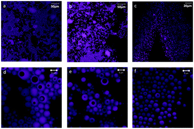
:![[thin space (1/6-em)]](https://www.rsc.org/images/entities/char_2009.gif) 35 were imaged using a confocal fluorescence microscope (Fig. 1). The systems contained spherical oil droplets (observed in magenta in the image) in the continuous, water phase. The 90
35 were imaged using a confocal fluorescence microscope (Fig. 1). The systems contained spherical oil droplets (observed in magenta in the image) in the continuous, water phase. The 90![[thin space (1/6-em)]](https://www.rsc.org/images/entities/char_2009.gif) :
:![[thin space (1/6-em)]](https://www.rsc.org/images/entities/char_2009.gif) 10 system had the largest internal phase content, 46%, with highly packed drops forming clusters (Fig. 1a). As the CNF content was increased (from 90
10 system had the largest internal phase content, 46%, with highly packed drops forming clusters (Fig. 1a). As the CNF content was increased (from 90![[thin space (1/6-em)]](https://www.rsc.org/images/entities/char_2009.gif) :
:![[thin space (1/6-em)]](https://www.rsc.org/images/entities/char_2009.gif) 10 to 65
10 to 65![[thin space (1/6-em)]](https://www.rsc.org/images/entities/char_2009.gif) :
:![[thin space (1/6-em)]](https://www.rsc.org/images/entities/char_2009.gif) 35), the volume of the aqueous phase increased from 43 to 76% and the packing of oil drop clusters was reduced (Fig. 1b and c). It can be observed that the emulsions produced are double or multiple emulsions, of the W/O/W type, wherein the drops of oil (dyed in the images) enclose dark areas which correspond to the water phase (see Fig. 1d–f).
35), the volume of the aqueous phase increased from 43 to 76% and the packing of oil drop clusters was reduced (Fig. 1b and c). It can be observed that the emulsions produced are double or multiple emulsions, of the W/O/W type, wherein the drops of oil (dyed in the images) enclose dark areas which correspond to the water phase (see Fig. 1d–f).
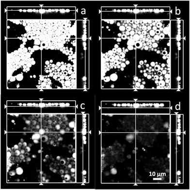
Fig. 2 gives more details about the morphology of the double emulsions (in the case of 90![[thin space (1/6-em)]](https://www.rsc.org/images/entities/char_2009.gif) :
:![[thin space (1/6-em)]](https://www.rsc.org/images/entities/char_2009.gif) 10 emulsion in Fig. 1a and d). In fact, it appears that the emulsions are of the drop-in-drop type. However, given the image resolution one cannot rule out the presence of multiple droplets inside the larger ones. In order to avoid confusion, we use here the generic term “double emulsions”, which can be taken to include multiple or single inner drops in the dispersed phase, as indicated above. Finally, there is no apparent differences in the partitioning (difference composition or otherwise) of the aqueous phase between the continuous and internal phases. However, this is a subject that needs further confirmation.
10 emulsion in Fig. 1a and d). In fact, it appears that the emulsions are of the drop-in-drop type. However, given the image resolution one cannot rule out the presence of multiple droplets inside the larger ones. In order to avoid confusion, we use here the generic term “double emulsions”, which can be taken to include multiple or single inner drops in the dispersed phase, as indicated above. Finally, there is no apparent differences in the partitioning (difference composition or otherwise) of the aqueous phase between the continuous and internal phases. However, this is a subject that needs further confirmation.
The main benefit in using double emulsions is the possibility to generate a larger interfacial area as compared to other morphologies, including simple emulsions. Furthermore, we were not successful in preparing electrospun fibers from simple emulsions. In contrast, the viscosity of the double emulsions, specifically that provided by nanocellulose, ensured a proper stabilization with no excess phases, yielding a system that could be easily processed in electrospinning.
The rheological behavior of the emulsions was determined in order to better understand the changes in morphology as observed by confocal microscopy. The flow curves of the emulsions were obtained to identify the possible changes in viscosity related to the effect of the PS/CNF ratio (Fig. 3). Only small changes in the viscosity at low shear rates of the emulsions was observed at varying PS![[thin space (1/6-em)]](https://www.rsc.org/images/entities/char_2009.gif) :
:![[thin space (1/6-em)]](https://www.rsc.org/images/entities/char_2009.gif) CNF ratios.
CNF ratios.
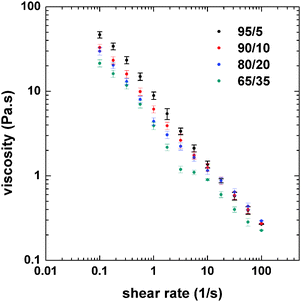 | ||
Fig. 3 Flow curves (at 25 °C) of double emulsions incorporating CNF aqueous dispersions and PS solutions with varying PS![[thin space (1/6-em)]](https://www.rsc.org/images/entities/char_2009.gif) : :![[thin space (1/6-em)]](https://www.rsc.org/images/entities/char_2009.gif) CNF ratios, as indicated. CNF ratios, as indicated. | ||
The highest viscosity was found for the 95![[thin space (1/6-em)]](https://www.rsc.org/images/entities/char_2009.gif) :
:![[thin space (1/6-em)]](https://www.rsc.org/images/entities/char_2009.gif) 5 system, which corresponded to the highest content of the internal phase. As the relative content of CNFs was increased, by changing the PS
5 system, which corresponded to the highest content of the internal phase. As the relative content of CNFs was increased, by changing the PS![[thin space (1/6-em)]](https://www.rsc.org/images/entities/char_2009.gif) :
:![[thin space (1/6-em)]](https://www.rsc.org/images/entities/char_2009.gif) CNF ratio from 95
CNF ratio from 95![[thin space (1/6-em)]](https://www.rsc.org/images/entities/char_2009.gif) :
:![[thin space (1/6-em)]](https://www.rsc.org/images/entities/char_2009.gif) 5 to 65
5 to 65![[thin space (1/6-em)]](https://www.rsc.org/images/entities/char_2009.gif) :
:![[thin space (1/6-em)]](https://www.rsc.org/images/entities/char_2009.gif) 35 (decreased internal phase content), the viscosity of the emulsion was reduced, especially at low shear rates. However, the differences in viscosity were minor at shear rates greater than 10 s−1. Fluorescence microscopy (Fig. 1 and 2) indicates that the size of the oil droplets (PS in toluene) decrease slightly as the composition ratio shifts from 90
35 (decreased internal phase content), the viscosity of the emulsion was reduced, especially at low shear rates. However, the differences in viscosity were minor at shear rates greater than 10 s−1. Fluorescence microscopy (Fig. 1 and 2) indicates that the size of the oil droplets (PS in toluene) decrease slightly as the composition ratio shifts from 90![[thin space (1/6-em)]](https://www.rsc.org/images/entities/char_2009.gif) :
:![[thin space (1/6-em)]](https://www.rsc.org/images/entities/char_2009.gif) 10 to 65
10 to 65![[thin space (1/6-em)]](https://www.rsc.org/images/entities/char_2009.gif) :
:![[thin space (1/6-em)]](https://www.rsc.org/images/entities/char_2009.gif) 35. While this affects the viscosity, the change in drop packing is more noticeable, from drop clusters that are highly packed to individual drops. When the drops are more packed (higher internal phase content), there is a higher drop–drop (inter-drop) friction, which results in a higher viscosity. For lower concentration of the internal phase, the interaction between drops is reduced (as shown in Fig. 1f), therefore the viscosity is also reduced. Thus, emulsion viscosity tended to increase with the internal phase (PS) content, due to the larger number density of drops, which increases the interfacial area and inter-drop friction.31
35. While this affects the viscosity, the change in drop packing is more noticeable, from drop clusters that are highly packed to individual drops. When the drops are more packed (higher internal phase content), there is a higher drop–drop (inter-drop) friction, which results in a higher viscosity. For lower concentration of the internal phase, the interaction between drops is reduced (as shown in Fig. 1f), therefore the viscosity is also reduced. Thus, emulsion viscosity tended to increase with the internal phase (PS) content, due to the larger number density of drops, which increases the interfacial area and inter-drop friction.31
Composite fibers from double emulsion systems
As shown previously, surfactants were used for efficient mixing of a hydrophobic nonpolar phase containing PS and the polar, aqueous CNF phase. The emulsions were used as precursor systems for fiber electrospinning. Typically, electrospinning of PS has been performed using water-miscible solvents such as tetrahydrofuran or dimethylformamide.32 To the best of our knowledge, only one report exists on electrospinning of PS in toluene or with other solvents, which demanded polymer concentrations above 20 wt%.25 Cellulose nanocrystals have been incorporated into the PS matrix utilizing toluene and non-ionic surfactants yet demanding freeze-drying of the cellulose prior to addition so as to facilitate good mixing.23 Electrospinning of CNF dispersions as such or incorporated into a polymer matrix is reported here for the first time.The emulsions with PS![[thin space (1/6-em)]](https://www.rsc.org/images/entities/char_2009.gif) :
:![[thin space (1/6-em)]](https://www.rsc.org/images/entities/char_2009.gif) CNF ratios of 95
CNF ratios of 95![[thin space (1/6-em)]](https://www.rsc.org/images/entities/char_2009.gif) :
:![[thin space (1/6-em)]](https://www.rsc.org/images/entities/char_2009.gif) 5, 90
5, 90![[thin space (1/6-em)]](https://www.rsc.org/images/entities/char_2009.gif) :
:![[thin space (1/6-em)]](https://www.rsc.org/images/entities/char_2009.gif) 10, 80
10, 80![[thin space (1/6-em)]](https://www.rsc.org/images/entities/char_2009.gif) :
:![[thin space (1/6-em)]](https://www.rsc.org/images/entities/char_2009.gif) 20 and 65
20 and 65![[thin space (1/6-em)]](https://www.rsc.org/images/entities/char_2009.gif) :
:![[thin space (1/6-em)]](https://www.rsc.org/images/entities/char_2009.gif) 35 were electrospun using 1.06 kV cm−1 field strength. Typically, electrospinning is performed for polymer solutions.25,33 Electrospinning of an emulsion has been attempted as a way to prepare core–shell fibers, using single or coaxial spinnerets.34,35 Electrospinning has been used to incorporate CNFs as fillers in a hydrophilic polymer, using a mixed dope.9,36,37 In contrast, the present investigation deals with a novel route that uses double emulsions to address the compatibility of CNF aqueous dispersions with nonpolar polymer solutions. As a validation, the electrospinning technique was used to produce composite fibers with PS
35 were electrospun using 1.06 kV cm−1 field strength. Typically, electrospinning is performed for polymer solutions.25,33 Electrospinning of an emulsion has been attempted as a way to prepare core–shell fibers, using single or coaxial spinnerets.34,35 Electrospinning has been used to incorporate CNFs as fillers in a hydrophilic polymer, using a mixed dope.9,36,37 In contrast, the present investigation deals with a novel route that uses double emulsions to address the compatibility of CNF aqueous dispersions with nonpolar polymer solutions. As a validation, the electrospinning technique was used to produce composite fibers with PS![[thin space (1/6-em)]](https://www.rsc.org/images/entities/char_2009.gif) :
:![[thin space (1/6-em)]](https://www.rsc.org/images/entities/char_2009.gif) CNF mass ratios from 95
CNF mass ratios from 95![[thin space (1/6-em)]](https://www.rsc.org/images/entities/char_2009.gif) :
:![[thin space (1/6-em)]](https://www.rsc.org/images/entities/char_2009.gif) 5 to 65
5 to 65![[thin space (1/6-em)]](https://www.rsc.org/images/entities/char_2009.gif) :
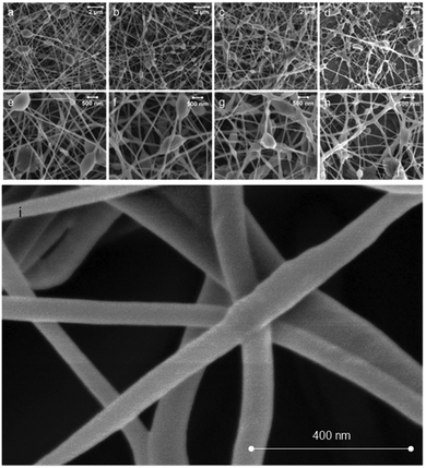
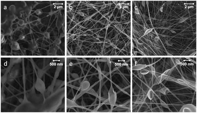
:![[thin space (1/6-em)]](https://www.rsc.org/images/entities/char_2009.gif) 35, yielding diameters ranging from 81 ± 12 nm to 110 ± 22 nm (Fig. 4). The PS concentration in the precursor emulsions was as low as 1.9 wt% (65
35, yielding diameters ranging from 81 ± 12 nm to 110 ± 22 nm (Fig. 4). The PS concentration in the precursor emulsions was as low as 1.9 wt% (65![[thin space (1/6-em)]](https://www.rsc.org/images/entities/char_2009.gif) :
:![[thin space (1/6-em)]](https://www.rsc.org/images/entities/char_2009.gif) 35 system), yet enabled fiber formation (Fig. 4d). Such low PS concentrations have not been reported before for successful electrospinning into fibers. It is noteworthy that PS solutions of 5.1 wt% concentration in toluene used here (the concentration corresponds to the PS concentration in the 90
35 system), yet enabled fiber formation (Fig. 4d). Such low PS concentrations have not been reported before for successful electrospinning into fibers. It is noteworthy that PS solutions of 5.1 wt% concentration in toluene used here (the concentration corresponds to the PS concentration in the 90![[thin space (1/6-em)]](https://www.rsc.org/images/entities/char_2009.gif) :
:![[thin space (1/6-em)]](https://www.rsc.org/images/entities/char_2009.gif) 10 system, Fig. 4b) resulted in droplets, but no fibers were formed on the collector (see ESI,† Fig. S2, left). Thus, the viscosity of the PS solution is a determining factor for continuous fiber formation.38 In previous studies, the increase in viscosity has been facilitated by using high molecular weight PS. However, in the present emulsion approach, the required viscosity of the spinning solution is easily attained by the addition of CNFs (see Fig. 3). The control of CNF concentration in the system results in apparent viscosities that enable the use of extremely low concentrations of PS for successful fiber spinning, which is otherwise not possible in the case of PS solutions. Spin coating of an emulsion with similar composition as the one presented in Fig. 2b was attempted, without incorporating PS in the toluene phase. However, no fibers were formed (see ESI,† Fig. S2, right). Drying or solvent exchange was avoided in the preparation of CNFs for incorporation into PS. In fact, despite the presence of water, it is demonstrated that electrospinning into fibers is achievable.
10 system, Fig. 4b) resulted in droplets, but no fibers were formed on the collector (see ESI,† Fig. S2, left). Thus, the viscosity of the PS solution is a determining factor for continuous fiber formation.38 In previous studies, the increase in viscosity has been facilitated by using high molecular weight PS. However, in the present emulsion approach, the required viscosity of the spinning solution is easily attained by the addition of CNFs (see Fig. 3). The control of CNF concentration in the system results in apparent viscosities that enable the use of extremely low concentrations of PS for successful fiber spinning, which is otherwise not possible in the case of PS solutions. Spin coating of an emulsion with similar composition as the one presented in Fig. 2b was attempted, without incorporating PS in the toluene phase. However, no fibers were formed (see ESI,† Fig. S2, right). Drying or solvent exchange was avoided in the preparation of CNFs for incorporation into PS. In fact, despite the presence of water, it is demonstrated that electrospinning into fibers is achievable.
Identification of the components, CNFs and PS, within the SEM images in Fig. 4 was not possible. In order to shed light on the distribution of the components in the fibers we performed low voltage SEM imaging (Fig. S1, ESI†). It is apparent that thin fibers merged or annealed together. Since, the interconnectedness of the network increased with CNF loading (Fig. 4), there is indication that the presence of CNFs is in part responsible for the observed morphology.
Traditional electrospinning uses a polymer solution that stretches under the applied electric field as a jet from the nozzle, forming a Taylor cone. Jet thinning and solvent evaporation lead to the formation of solid fibers on the collector. The use of emulsions as spinning dope adds a dimension to the process since it consists of droplets that are immiscible with the continuous phase. As a result, the stretching of the two phases produces unique structures, depending on the morphology of the precursor emulsion. Bazilevsky et al.35 have shown that electrospinning of an emulsified system leads to fibers with a core–shell structure, with the dispersed droplets in the core and the continuous matrix as the shell. As demonstrated by confocal fluorescence imaging and our previous findings,28 CNFs in water are the continuous phase in the precursor double emulsions. As such, if one speculates that core–shell geometries are formed then the CNF phase would likely be located in the shell of the fibers. Consequently, the amount of CNF (in the continuous phase) would affect the fiber diameter and morphology. Despite the fact that we did not attempt to determine the inner morphology of the fibers, it is interesting to note that the fiber diameter increased (from 81 to 110 nm) as the amount of CNF increased (from 5 to 65%) and the morphology changed from individual fibers into an interconnected fiber web (see Fig. 4). The electrospun fiber mats exhibited some beading. In fact, bead formation is common in electrospun PS fibers.24,27 No correlation between the number density of beads and the CNF concentration was found.
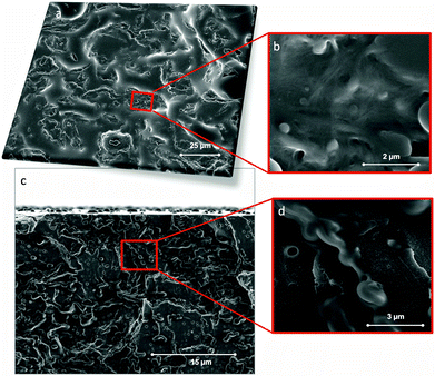
In order to gain further insight into the role of CNFs and PS components in the composite, the same emulsions used for electrospinning were dried in an vacuum oven (70 °C) followed by pressing (hot-press, 150 °C) into composite films. SEM plane and cross-section images of the film (90![[thin space (1/6-em)]](https://www.rsc.org/images/entities/char_2009.gif) :
:![[thin space (1/6-em)]](https://www.rsc.org/images/entities/char_2009.gif) 10 system) are shown in Fig. 5a–d. The SEM images indicate well-dispersed fibrils in the polymer matrix. A few, small void spaces are observed and protuberances, likely CNF aggregates, appear to be surrounded by PS. Material distribution was quite homogeneous if compared with typical cellulose–reinforced composites.
10 system) are shown in Fig. 5a–d. The SEM images indicate well-dispersed fibrils in the polymer matrix. A few, small void spaces are observed and protuberances, likely CNF aggregates, appear to be surrounded by PS. Material distribution was quite homogeneous if compared with typical cellulose–reinforced composites.
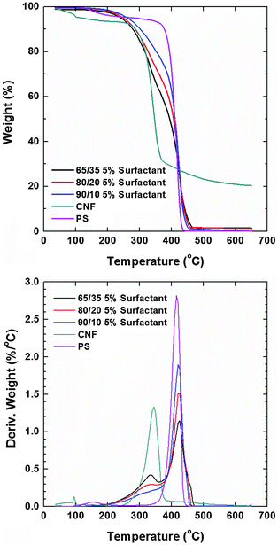
Thermograms (TGA) of the composite films recorded in a nitrogen atmosphere revealed that the main weight loss of neat CNFs took place at ca. 345 °C while that of polystyrene occurred at ca. 415 °C (Fig. 6). Prior to degradation, the evaporation of the residual solvent was noted in both cases. The degradation profiles of PS composites with CNF loading of 35, 20 and 10 wt% (and 5% of the surfactant) showed the individual contribution of the respective components (included as reference). The degradation temperature in an oxygen atmosphere of the nonionic surfactants is higher than 250 °C but they are more stable in a nitrogen atmosphere. Therefore, their small signal contribution overlaps with that of nanocellulose. The thermal stability roughly followed the concentration of PS in the composite (systems with higher PS content were more stable). The observation of the derivative of the weight loss revealed that the lower degradation peak assigned to CNFs had a negligible shift. Remarkably, the degradation peak assigned to PS (main component) shifted to higher T with CNF loading. Dynamic scanning calorimetry (DSC) of the composite samples was conducted for a maximum temperature corresponding to the 5% weight loss observed in TGA runs (200 °C). We note that the melting of PS occurred at ∼240 °C but at this temperature cellulose degradation started to occur. No transitions were observed below this temperature and therefore, it was not possible to further elucidate phase mixing via this technique.
Effect of surfactant loading and aqueous phase conductivity
So far, we have shown that aqueous CNF dispersions can be incorporated with non-polar polymer solutions in double emulsions, which can be used to synthesize composite materials. The role of the surfactant component with respect to the characteristics of the composite fibers is discussed next. The surfactant concentration was varied between 1 and 13% based on the total volume of the precursor emulsion and the effects on emulsification and fiber formation were investigated. Upon storage for approximately one month the emulsions with the highest surfactant concentration, 13 wt%, experienced creaming since they separated into a translucent, organic upper phase and an aqueous, opaque lower phase. The emulsions with lower surfactant concentrations, 1, 3, 5 and 7 wt%, remained unchanged during the observation time period (one month).Emulsions containing 1, 3 and 13% surfactant mixtures were electrospun into fibers (see Fig. 7 for SEM images of the resulting fiber webs). The webs included beaded fibers, as a result of the combined effects of fluid conductivity, viscosity and surface tension.26 The conductivity of the aqueous phase affects bead formation even in cases where the aqueous phase is dispersed in an organic, continuous medium.39 In this study, both the fiber diameter and the beading were affected strongly by changes in surface tension (Fig. 7): more beading and thicker fibers were favored under conditions of low surface tension (high surfactant concentration). As the surfactant concentration decreased, the fiber diameter decreased. Interestingly the beading structure changed from spherical to asymmetric, cup-shaped structures, similar to those reported by Eda et al.26 but for significantly higher PS concentrations compared to those used in the present study. Lin et al.40 studied the effect of ionic surfactants on bead formation during PS electrospinning and other authors have indicated decreased beading by increasing the PS concentration (or reducing surfactant concentration).41 Furthermore, nonionic surfactants did not affect beading but decreased the fiber diameter. Overall, our results of CNF-stabilized emulsions are in agreement with these observations (Fig. 7).
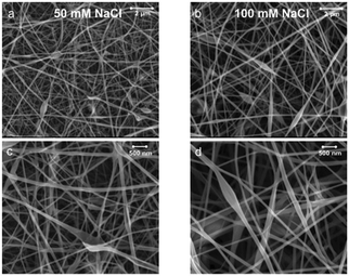
The conductivity is known to be critical to control fiber beading during electrospinning.27,42 Our results indicate beads that are smaller in size and lower in number density with an increase of the conductivity of the aqueous phase (50 and 100 mM NaCl concentration) (Fig. 8). This is explained by improved stretching of the spinning emulsion.42,43 This is because the CNF aqueous dispersion is the continuous phase in the double emulsion. Therefore, the results indicate that fiber quality and morphology can be controlled by the conductivity (salt concentration) in the CNF dispersion, which affects stretching under the applied electric field.
Dynamic mechanical analyses were performed with the PS/CNF composite webs. However, the results were not reproducible given the variations in density of the samples, fiber diameter, inter-fiber contact area and other physical factors that depend on the exact conditions of spinning (time, humidity, etc.). We note, however, that the webs were brittle and may not be of interest as far as mechanical performance is concerned. Other polymer combinations may be more desirable. While our main aim was not to develop fiber strength or reinforcing capabilities, our efforts were directed towards a first proof-of-concept approach to compatibilize never-dried nanocellulose with nonpolar polymers. This is the starting point in developing advanced systems for functions that require the combination of CNFs with non-polar polymers. This includes membranes with different hydrophilicity–hydrophobicity balance, sensors, fiber network templates and scaffolds, oil-adsorbing filtration membranes, etc. As a side point, there is an expectation that this methodology can be used to produce surfactant-loaded re-dispersible CNFs after drying.
Overall, CNF-stabilized double emulsions are demonstrated as effective systems to produce composites with nonpolar polymers. Specifically, here we demonstrate composite fibers that displayed enhanced spinnability upon CNF loading. This enables extremely low concentrations of PS in the emulsion that still facilitate fiber formation (water content as high as 76 wt% in the precursor emulsion was possible). The high cellulose loading and low PS concentration to spin fibers, as presented in this study, is an alternative route to produce CNF-based composite fibers with no need for prior drying of the CNF dispersion.
Conclusions
Defect-free PS nanofibers with high CNF loading (up to 35%) were produced by formulating double emulsions containing aqueous dispersions of CNFs and integrated with PS in the nonpolar phase. The emulsions stabilized by CNFs enhance interactions between the components at the O/W interface and resulted in a compatible system toward composite structures with homogenous mass distribution. Overall, double emulsions are proposed as a platform for the compatibilization of CNFs with nonpolar components while avoiding the need for drying or solvent exchange prior to processing. Furthermore, the use of emulsions as precursors of solvent (water)-free solid materials can facilitate efforts in the re-dispersion of CNFs.Acknowledgements
OJR is grateful for the support provided by the Academy of Finland through its Centres of Excellence Programme (2014–2019) and under project ‘‘Molecular Engineering of Biosynthetic Hybrid Materials Research’’ (HYBER). Also, funding by Halliburton Company is gratefully acknowledged. Dr Eva Johannes at Cellular and Molecular Imaging Facility at North Carolina State University is acknowledged for confocal imaging. Chuck Mooney (Analytical Instrumentation Facility) at North Carolina State University is acknowledged for help with SEM imaging.References
- A. Dufresne, Nanocellulose: From Nature to High Performance Tailored Materials, Walter de Gruyter, Munchen, Germany, 2012 Search PubMed.
- I. Siro and D. Plackett, Cellulose, 2010, 17, 459–494 CrossRef CAS.
- H. Abdul Khalil, A. Bhat and A. Ireana Yusra, Carbohydr. Polym., 2012, 87, 963–979 CrossRef CAS.
- S. J. Eichhorn, A. Dufresne, M. Aranguren, N. E. Marcovich, J. R. Capadona, S. J. Rowan, C. Weder, W. Thielemans, M. Toman, S. Renneckar, W. Gindl, S. Veigel, J. Keckes, H. Yano, K. Abe, M. Nogi, A. N. Nakagaito, A. Mangalam, J. Simonsen, A. S. Benight, A. Bismarck, L. A. Berglund and T. Peijs, J. Mater. Sci., 2010, 45, 1–33 CrossRef CAS.
- C. Zhou, R. Chu, R. Wu and Q. Wu, Biomacromolecules, 2011, 12, 2617–2625 CrossRef CAS PubMed.
- Y. Habibi, S. Aouadi, J. Raquez and P. Dubois, Cellulose, 2013, 20, 2877–2885 CrossRef CAS.
- B. Peng, N. Dhar, H. Liu and K. Tam, Can. J. Chem. Eng., 2011, 89, 1191–1206 CrossRef CAS.
- M. S. Peresin and O. J. Rojas, in Handbook of green materials, ed. K. Oksman, A. Bismark, M. Sain, A. P. Mathew and O. J. Rojas, World Scientific Pub. Co., Singapore, 2014, pp. 163–183 Search PubMed.
- M. S. Peresin, Y. Habibi, J. O. Zoppe, J. J. Pawlak and O. J. Rojas, Biomacromolecules, 2010, 11, 674–681 CrossRef CAS PubMed.
- M. Ago, K. Okajima, J. E. Jakes, S. Park and O. J. Rojas, Biomacromolecules, 2012, 13, 918–926 CrossRef CAS PubMed.
- E. E. Urena-Benavides, P. J. Brown and C. L. Kitchens, Langmuir, 2010, 26, 14263–14270 CrossRef CAS PubMed.
- R. Endo, T. Saito and A. Isogai, Polymer, 2013, 54, 935–941 CrossRef CAS.
- D. Bondeson and K. Oksman, Compos. Interfaces, 2007, 14, 617–630 CrossRef CAS.
- D. Liu, X. Sun, H. Tian, S. Maiti and Z. Ma, Cellulose, 2013, 20, 2981–2989 CrossRef CAS.
- P. K. Annamalai, K. L. Dagnon, S. Monemian, E. J. Foster, S. J. Rowan and C. Weder, Biomacromolecules, 2013, 6, 967–976 Search PubMed.
- G. Siqueira, A. P. Mathew and K. Oksman, Compos. Sci. Technol., 2011, 71, 1886–1892 CrossRef CAS.
- S. Coulibaly, A. Roulin, S. Balog, M. V. Biyani, E. J. Foster, S. J. Rowan, G. L. Fiore and C. Weder, Macromolecules, 2013, 47, 152–160 CrossRef.
- O. J. Rojas, G. A. Montero and Y. Habibi, J. Appl. Polym. Sci., 2009, 113, 927–935 CrossRef CAS.
- R. Sen, B. Zhao, D. Perea, M. E. Itkis, H. Hu, J. Love, E. Bekyarova and R. C. Haddon, Nano Lett., 2004, 4, 459–464 CrossRef CAS.
- G. Chen, C. Wu, W. Weng, D. Wu and W. Yan, Polymer, 2003, 44, 1781–1784 CrossRef CAS.
- J. R. Li, J. R. Xu, M. Q. Zhang and M. Z. Rong, Carbon, 2003, 41, 2353–2360 CrossRef CAS.
- S. T. Georgopoulos, P. Tarantili, E. Avgerinos, A. Andreopoulos and E. Koukios, Polym. Degrad. Stab., 2005, 90, 303–312 CrossRef CAS.
- C. L. Casper, J. S. Stephens, N. G. Tassi, D. B. Chase and J. F. Rabolt, Macromolecules, 2004, 37, 573–578 CrossRef CAS.
- K. Lee, H. Kim, H. Bang, Y. Jung and S. Lee, Polymer, 2003, 44, 4029–4034 CrossRef CAS.
- Z. Huang, Y. Zhang, M. Kotaki and S. Ramakrishna, Compos. Sci. Technol., 2003, 63, 2223–2253 CrossRef CAS.
- G. Eda, J. Liu and S. Shivkumar, Mater. Lett., 2007, 61, 1451–1455 CrossRef CAS.
- T. Uyar and F. Besenbacher, Polymer, 2008, 49, 5336–5343 CrossRef CAS.
- C. A. Carrillo, T. E. Nypelö and O. J. Rojas, J. Colloid Interface Sci., 2015, 445, 166–173 CrossRef CAS PubMed.
- C. Stubenrauch, Microemulsions: background, new concepts, applications, perspectives, Wiley, 2009 Search PubMed.
- Y. Li, F. K. Ko and W. Y. Hamad, Biomacromolecules, 2013, 14, 3801–3807 CrossRef CAS PubMed.
- Y. Otsubo and R. Prud'homme, Rheol. Acta, 1994, 33, 29–37 CrossRef CAS.
- G. Fadat, I. Pettersson and M. Rigdahl, Nord. Pulp Pap. Res. J., 1986, 1, 30–36 CAS.
- A. K. Higham, C. Tang, A. M. Landry, M. C. Pridgeon, E. M. Lee, A. L. Andrady and S. A. Khan, AIChE J., 2014, 60, 1355–1364 CrossRef CAS.
- A. Yarin, Polym. Adv. Technol., 2011, 22, 310–317 CrossRef CAS.
- A. V. Bazilevsky, A. L. Yarin and C. M. Megaridis, Langmuir, 2007, 23, 2311–2314 CrossRef CAS PubMed.
- E. S. Medeiros, L. H. Mattoso, E. N. Ito, K. S. Gregorski, G. H. Robertson, R. D. Offeman, D. F. Wood, W. J. Orts and S. H. Imam, J. Biobased Mater. Bioenergy, 2008, 2, 231–242 CrossRef.
- M. E. Vallejos, M. S. Peresin and O. J. Rojas, J. Polym. Environ., 2012, 20, 1075–1083 CrossRef CAS.
- G. Eda and S. Shivkumar, J. Mater. Sci., 2006, 41, 5704–5708 CrossRef CAS.
- P. M. Vlahovska, J. Fluid Mech., 2011, 670, 481–503 CrossRef.
- T. Lin, H. Wang, H. Wang and X. Wang, Nanotechnology, 2004, 15, 1375–1381 CrossRef CAS.
- J. Zheng, A. He, J. Li, J. Xu and C. C. Han, Polymer, 2006, 47, 7095–7102 CrossRef CAS.
- Q. P. Pham, U. Sharma and A. G. Mikos, Tissue Eng., 2006, 12, 1197–1211 CrossRef CAS PubMed.
- C. Mit-uppatham, M. Nithitanakul and P. Supaphol, Macromol. Symp., 2004, 216, 293–300 CrossRef CAS.
Footnotes |
| † Electronic supplementary information (ESI) available. See DOI: 10.1039/c5sm02578h |
| ‡ Current address: University of Natural Resources and Life Sciences, Vienna. Konrad Lorenz Strasse 24, 3430 Tulln, Austria. |
| This journal is © The Royal Society of Chemistry 2016 |

