DOI:
10.1039/C5SM01649E
(Paper)
Soft Matter, 2016,
12, 859-866
Nanotribological and wetting performance of hierarchical patterns†
Received
6th July 2015
, Accepted 27th October 2015
First published on 27th October 2015
Abstract
Surface modification is a promising method to solve the tribological problems in microsystems. To modify the surface, we fabricated hierarchical patterns with different pitches of nano-scale features and different surface chemistries. Micro- and nano-patterns with similar geometrical configurations were also fabricated for comparison. The nano-tribological behavior of the patterns was investigated using an atomic force microscope at different relative humidity levels (5% to 80%) and applied normal loads (40 nN to 120 nN) under a constant sliding velocity. The results showed significant enhancement in the de-wetting and tribological performance of the hierarchical patterns compared with those of flat and micro- and nano-patterned surfaces. The PTFE-coated hierarchical patterns showed similar dynamic contact angles (advancing and receding) to those of the real lotus leaf. The influence of relative humidity on adhesion and friction behavior was found to be significant for all the tested surfaces. The tribological performance was improved as the pitch of the nano-scale geometry of the hierarchical pattern increased, even though the wetting property was not influenced significantly. A model was proposed based on the role of intermolecular force to explain the effect of the pitch of the hierarchical patterns on the adhesion and friction behavior. According to the model based on the molecular force, the contact between a ball and the patterned surface was a multi-asperity contact, contrary to the single-asperity contact predicted by the Johnson–Kendall–Roberts (JKR) and Maugis–Dugdale (MD) models. The strong intermolecular forces, which are activated in the confined spaces between the adjacent nano-pillars and the ball, contributed to the contact area and hence the adhesion and friction forces.
1. Introduction
The ratio of the surface area to volume increases significantly at the micro- and nano-scales, resulting in the surface forces having a greater influence on the performance of micro- and nano-scale systems. The resultant surface forces are determined by the intermolecular forces of the interacting phases. These intermolecular forces control the tribological (adhesion and friction) and wetting behavior of the micro- and nano-scale systems.1,2 Low friction and adhesion improve the durability and efficiency of many micro-/nano-electromechanical systems (MEMS/NEMS).1,3–8 The use of low surface energy material and texturing is usually recommended to reduce the friction and adhesion among the interacting surfaces. Inspired by nature, many different textural geometrical forms have been used to provide significant improvement in the tribological behavior of MEMS/NEMS. Hierarchical patterns have shown better performance than their micro- and nano-counterparts. To achieve improved performance, we must understand the role of the micro- and nano-scalar features of the hierarchical patterns in the tribological and wetting behaviors. Several different parameters determine the performance of the patterned structures, including the surface chemistry and the pitch (distance between the pillars), diameter, and height of the micro- and nano-features.6,9–11 In addition, the shape of these features also contributes to their tribological and wetting behavior. Contrary to surface chemistry, the relationship between geometric parameters and friction and adhesion is quite complex. This complex relationship is partly because of the mechanical integrity of the pattern geometry. The deformation induced by high stresses can contribute to the unpredictable behavior of the patterns. The material and geometric parameters determine the degree of deformation for a given pattern. Although the beneficial effects of hierarchical patterns on adhesion and friction have been reported,1,12–14 the effect of the pitch of nano-scale features has not been explored to a significant extent.
Our aim was to determine the degree of influence of the pitch of the nano-pillar on the tribological and wetting behavior of the patterns. Thus, we fabricated patterns with two different surface chemistries to investigate the effect of pitch. Flat, micro- and nano-patterned surfaces were also fabricated as control surfaces for comparison. The effect of capillary forces on the tribological behavior of the flat and patterned surfaces was investigated at different relative humidity levels. The results were analyzed using contact mechanics theories along with intermolecular forces.
2. Experimental details
Table 1 lists the dimensions of the hierarchical polymethylmethacrylate (PMMA) patterns fabricated (Fig. 1) using the capillary force lithography technique.15 For comparison, micro- and nano-patterns with similar geometric dimensions were also fabricated. PMMA patterns were also coated with polytetrafluoroethylene (PTFE) using the C4F8 plasma activation method to lower the surface energy. The root-mean square roughness (Rrms) values of the PMMA- and PTFE-coated flat surfaces measured using an atomic force microscope were approximately 2 ± 1 nm and 1.5 ± 0.75 nm. The thickness of the PTFE coating, measured using an ellipsometer, was approximately 20 nm. The dynamic (advancing and receding) contact angles were measured by the captive drop approach using de-ionized (DI) water. The reported results are the average of five consecutive measurements at random locations. Prior to testing, all samples were cleaned ultrasonically in a bath of DI water and dried with N2 gas. The wetting experiments were performed in a controlled environment at 24 ± 1 °C and 45 ± 5% RH.
Table 1 Geometric dimensions of the hierarchical, nano- and micro-patterns
| Pattern |
Dimensions of micro-pillars |
Dimensions of nano-pillars |
| Diameter D (μm) |
Height H (μm) |
Pitch P (μm) |
Diameter D (nm) |
Height H (nm) |
Pitch P (nm) |
| Hierarchical |
3.0 |
2.5 |
4 |
250 |
220 |
500 |
625 |
750 |
1000 |
| Nano |
— |
— |
— |
250 |
220 |
500 |
— |
— |
— |
| Micro |
3.0 |
2.5 |
4 |
— |
— |
— |
— |
— |
— |
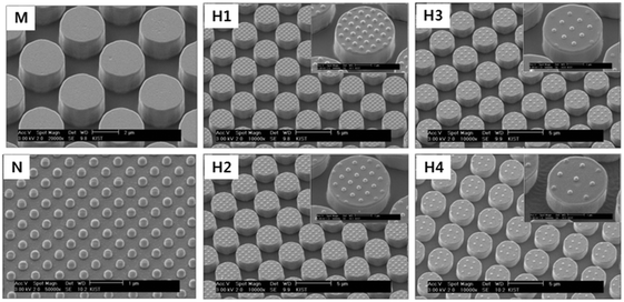 |
| | Fig. 1 Scanning electron micrographs of the fabricated patterns: M – micro, N – nano, H1 – hierarchical pattern with 500 nm pitch nano-pillars; H2 – hierarchical pattern with 625 nm pitch nano-pillars; H3 – hierarchical pattern with 750 nm pitch nano-pillars; H4 – hierarchical pattern with 1000 nm pitch nano-pillars. | |
Adhesion and friction experiments were performed using an atomic force microscope (AFM) at different relative humidity (RH) levels ranging from 5 to 80% and at a constant temperature (24 ± 1 °C). The relative humidity inside the AFM chamber was controlled (±1%) using a specially developed set-up (Fig. S1, ESI†) and measured using a hygrometer (Tecpel, Taiwan). The precise control of the dry and wet air through flow control valves provides the desired levels of relative humidity in the test chamber. Triangular cantilevers with borosilicate glass ball tips having a radius of curvature of 5 μm were used for all the experiments. For friction measurements, the normal load was varied from 40 to 120 nN at a constant sliding velocity of 5 μm s−1, with a scan area equal to 20 × 20 μm2. The friction force was calculated using the trace minus retrace method (TMR).16 Measurements were performed at least 20 times for each experiment, and the average values are reported here.
3. Results and discussion
3.1 Wetting
Fig. 2 shows the advancing (θa) and receding (θr) contact angles of the hierarchical, micro- and nano-patterns. The contact angle hysteresis (CAH), which is calculated as the difference between the advancing and receding angles, is also shown in Fig. 2. The CAH results of the flat surfaces are also shown for comparison. The PTFE-coated hierarchical structures showed the smallest CAH (<10°) compared with those of their micro- and nano-counterparts. The advancing and receding angles of the PTFE-coated hierarchical patterns were similar to those of the lotus leaf (Fig. 2). The highest CAH of 77° was observed for the PMMA micro-patterned surface. In general, the PMMA flat and patterned surfaces showed higher CAH than the PTFE-coated counterparts, which resulted from the difference in the surface energies of PMMA (γPMMA ≈ 41 J m−2) and PTFE (γPTFE ≈ 18 J m−2). The higher surface energy of PMMA led to more effective pinning of the receding contact line during the lateral motion of the droplet compared with PTFE, which resulted in lower receding angles for PMMA and higher CAH.
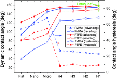 |
| | Fig. 2 Dynamic contact angle (advancing and receding) and contact angle hysteresis (CAH) of the flat and patterned polymethylmethacrylate (PMMA) and polytetrafluoroethylene (PTFE) surfaces. The advancing and receding angles of the lotus leaf reported in ref. 18 are shown for comparison. | |
Among all the patterned and flat surfaces, the surfaces with hierarchical patterns showed the smallest CAH, which is related to the wetting states of the patterns. Due to the inability of the spherical shape to pin the three-phase contact (small critical angle) and the sagging depth of the liquid–air interface being larger than the height of the pillar, the water penetrated the nano-patterns and resulted in a Wenzel state.17–19 Earlier finite element method (FEM) simulations and Gibbs free energy predictions showed the presence of the Wenzel state for nano-patterns and a meta-stable state for the hierarchical and micro-patterns.19 Because of the persistence of the Wenzel state, the nano-patterns showed higher CAH in comparison to the hierarchical patterns. In the case of the micro-patterns, the penetration of the liquid–air interface is limited by effective pinning of the liquid–air interface. The critical angle (θc) given as17
is higher for the cylinder shaped micro-pillars in comparison to the spherical shaped nano-pillars, where
ψ is a local geometric angle formed by the local tangent line with the horizontal plane. Furthermore, the height of the micro-pillars is also higher than the sagging depth of the liquid–air interface. The contribution of both these factors resulted in a meta-stable state for the micro-pillars. The entrapment of air beneath the liquid–air interface in a meta-stable state results in an additional decrease in the free energy of the system. For PTFE-coated micro-pillars, the penetration will be further reduced due to the larger critical angle resulting from the higher advancing angle of PTFE. Furthermore, the lateral motion of the three-phase line would also be restricted, which lowers the receding angle, thereby causing an increase of CAH due to pinning of the liquid–air interface at the edge of the micro-pillar.
The PTFE-coated hierarchical patterns, which showed the lowest CAH among all the investigated patterns, had similar advancing and receding angles to those observed for the lotus leaf. In the case of hierarchical patterns, both the nano- and micro-pillars worked in tandem, which effectively lowered the CAH. Similar to the micro-patterns, the micro-pillars of the hierarchical patterns restricted the penetration of the water into the hierarchical patterns by effectively pinning the liquid–air interface. During the lateral motion of the three-phase line, the nano-pillars on top of the micro-pillars aid in lowering the CAH by effectively de-pinning the contact line. Furthermore, the change in the pitch of the nano-pillars had minimal influence on the advancing and receding contact angles of the hierarchical patterns. This minimal effect is related to the nominal energy-barrier provided by the nano-pillars of the hierarchical patterns compared with the energy barrier from the entrapped air of the micro-pillars. The small contribution of the pitch of nano-pillars to energy barrier resulted in minimal effect on the contact angles.
3.2 Adhesion and friction
Fig. 3 shows the adhesion performance of all the patterns at different relative humidity levels. The results show that the adhesion of the patterned surfaces decreased to a significantly greater extent than that of the flat surfaces. The highest adhesion was observed for the flat PMMA surface, followed by the PTFE-coated flat surface. The lowest adhesion was observed for the PTFE-coated hierarchical patterns. The hierarchical patterns showed more than 20 times lower adhesion than the flat surfaces. Arzt et al.20 showed that the contact splitting results in an increase of adhesion for the same apparent area; however, the effect of true contact area and the effective elastic modulus (material and structural) must also be taken into consideration.21 We observed a decrease in adhesion with a decrease in the true contact area, as also reported by King et al.21 Furthermore, the decrease in adhesion in our case is also due to the high effective modulus, which inversely influences the conformability of the surfaces. The decrease in the adhesion of the hierarchical patterns was evident, irrespective of the surface chemistry. The mean value of adhesion of the hierarchical patterns further decreased with an increase in the pitch of the nano-pillars. The significance of the pitch of the nano-scale pillars was tested using the ANOVA post hoc Tukey test, indicating a p-value < 0.05. At 60% RH, with an increase in the pitch of the nano-pillars from 500 nm to 1000 nm, the adhesion force decreased from 63 to 39 nN for the PTFE-coated surface and from 75 to 46 nN for the PMMA patterns (an approximately 38% decrease for both cases).
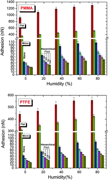 |
| | Fig. 3 Adhesion force of the flat and patterned polymethylmethacrylate (PMMA) and polytetrafluoroethylene (PTFE) coated surfaces at different relative humidity levels. | |
Fig. 4 shows the friction force for different normal loads for all the patterns at 40% relative humidity levels. Consistent with the adhesion behavior, the hierarchical patterns also had the lowest friction force. Compared with the flat surfaces, the friction force was reduced significantly, with the minimum friction force observed for the hierarchical patterns with nano-pillars having a pitch of 1000 nm. The hierarchical patterns also showed significantly lower friction force than the micro-patterns. Furthermore, a nearly identical relationship between the pitch of the nano-pillars of the hierarchical patterns and the friction force was observed for both surface chemistries, irrespective of the normal loads (rate of change of friction with pitch). This result indicated that the topography had a significant effect in controlling the friction of the hierarchical patterns for a given surface chemistry.
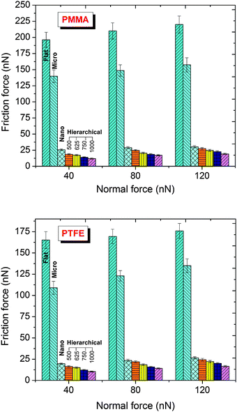 |
| | Fig. 4 Friction force of the flat and patterned polymethylmethacrylate (PMMA) and polytetrafluoroethylene (PTFE) coated surfaces under different normal loads and at 40% relative humidity. | |
The relative humidity had a significant influence on the adhesion and friction of all the flat and patterned surfaces (Fig. 3, 5 and Fig. S2, ESI†). The adhesion and friction both increased with an increase in the relative humidity. In comparison to 5% RH, the adhesion of the flat PMMA surface increased by approximately 29% at 40% RH, whereas in the case of the PTFE-coated flat surface, the increase in adhesion was approximately 18% for the same relative humidity levels. The friction force also significantly increased with an increase in relative humidity from 5 to 60% RH; however, a further increase in the relative humidity over 60% RH resulted in a slight decrease in the friction force. The increase in adhesion and friction with relative humidity is related to an increase in the capillary force (discussed in detail in a subsequent paragraph). However, at higher relative humidity, the counter lubrication effect is initiated and lowers the friction. A balance between the two counteracting effects determines the overall behavior of the system.
The difference in the adhesion and friction behaviors of the PMMA- and PTFE-coated surfaces can be explained based on the intermolecular forces and the capillary forces. During the interaction of the AFM tip (borosilicate glass ball tip with a diameter of 10 μm) with the flat/textured surfaces, both the short- and long-range forces contributed to the overall behavior of the system. These forces included attractive van der Waals, electrostatic, solvation and hydration forces. The combined effect of these forces, along with the capillary force that originated due to condensation of the water vapor in the air on the solid surface, contributed to the adhesion and, hence, the friction force.
The van der Waals force is related to the Hamaker constant A by22
| |  | (2) |
The value of
A for the two macroscopic phases 1 and 2 interacting through medium 3 can be estimated by the Lifshitz theory
| |  | (3) |
According to the Lifshitz theory, the retarded part of the Hamaker constant is a function of the refractive index,
n, and the absorption frequency,
νe. The values of the Hamaker constant for the interaction between the borosilicate indenter ball (phase 1) and the PMMA- or PTFE-coated surfaces (phase 2) interacting through water as a medium (phase 3) were calculated using the values of the parameters given in Table S1 (ESI
†). For PMMA, the value of
A is approximately six times greater than that for PTFE (Table S1, ESI
†). This difference indicated greater attraction and, hence, greater adhesion of the borosilicate glass ball indenter to PMMA than to the PTFE-coated surface. Furthermore, the capillary force, which is related to the interfacial energies of the interacting solid surfaces, is modulated with the hydration forces. The capillary force
22 shown in
eqn (4) was also greater for the surface of PMMA than for the surface of PTFE
| |  | (4) |
where
Rb is the radius of the borosilicate glass ball,
γlv is the surface tension of the liquid (water in the present case) and
D is the distance between the glass ball and the surface of the solid. With the values of all the parameters being identical for both surfaces, the capillary force was controlled primarily by the contact angle
θ between the water and the surface of the solid. Given that the static contact angles
θ of PMMA and PTFE with water are 67° and 110°, respectively, and that of borosilicate glass is 32°, the capillary force was obviously higher for the PMMA-coated surface compared with the PTFE-coated surface (as shown in
Fig. 3 and 5). This difference caused a lesser adhesion force for the PTFE-coated surface than for the PMMA-coated surface.
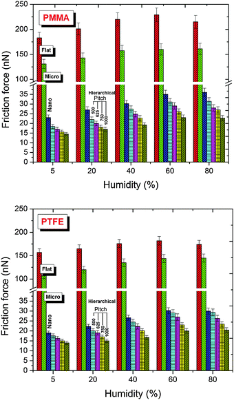 |
| | Fig. 5 Friction force of the flat and patterned polymethylmethacrylate (PMMA) and polytetrafluoroethylene (PTFE) coated surfaces at different relative humidity levels and at a normal load of 120 nN. The results for normal loads of 40 nN and 80 nN are provided in Fig. S2 (ESI†). | |
Furthermore, the difference in the tribological behaviors among the patterns of identical surface chemistry was a consequence of the change in the apparent contact area. Various contact mechanics models have been suggested in the literature for estimating the contact area, pressure and depth. Johnson and Greenwood23 presented an adhesion map for determining the appropriate contact model pertaining to the particular contact situation. This map relates the transition parameters λ and/or μ proposed by Maugis24 and Tabor,25 respectively, with the dimensionless adhesion force, ![[P with combining macron]](https://www.rsc.org/images/entities/i_char_0050_0304.gif) = P/πwR, to determine the model that is best suited for the particular contact condition. The transition parameters are functions of the theoretical stress σ0 = 1.03w/Z0, work of adhesion w, and equivalent radius R = [1/r1 + 1/r2]−1,
= P/πwR, to determine the model that is best suited for the particular contact condition. The transition parameters are functions of the theoretical stress σ0 = 1.03w/Z0, work of adhesion w, and equivalent radius R = [1/r1 + 1/r2]−1,
| |  | (5) |
where
r1 and
r2 are the radii of the contact geometries and
E* is the equivalent elastic modulus, given by
E* = [(1 −
v12)/
E1 + (1 −
v22)/
E2]
−1. Furthermore,
P is the normal load on the indenter and
Z0 is an equilibrium separation, as in the Lennard-Jones potential. For PMMA the value of
λ varies from 2.05 to 4.1 with
Z0 in the range of 4 Å to 2 Å, respectively. Similarly, for PTFE the
λ varies from 5.5 Å to 12.9 Å, respectively. For the present situation, the contact lies at the boundary separating the Maugis–Dugdale (MD)
24 regime from the Johnson–Kendall–Roberts (JKR) regime
26 (
Fig. 6(a)). Thus, we calculated the contact radius and the depth using both the MD and JKR models, as shown in
Fig. 6(b). Table S2 (ESI
†) provides the values of the different parameters used in the calculations. In the case of the JKR model, the estimations of contact radius
a and depth
δ were given as
| |  | (6) |
| |  | (7) |
Obtaining these values is more complicated in the case of the MD model. The contact parameters from the MD model are expressed in a dimensionless form as
| |  | (9) |
| |  | (10) |
where
m is the ratio of the extended contact radius,
c, due to the adhesive force to the contact radius
a. The contact radii calculated from the JKR and MD models were much smaller than the spacing between the nano-pillars. For example, at a maximum load of
P = 120 nN, the contact radii predicted by the JKR and MD models for the PMMA-coated hierarchical patterns were 46.2 and 23 nm, respectively, and those for PTFE-coated hierarchical patterns were 81.7 nm and 38 nm, respectively.
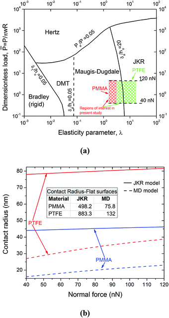 |
| | Fig. 6 (a) Adhesion map (after Johnson and Greenwood23) showing the region of interest for this study; (b) values of the contact radius for the flat and patterned polymethylmethacrylate (PMMA) and polytetrafluoroethylene (PTFE) coated surfaces using the Johnson–Kendall–Roberts (JKR) and Maugis–Dugdale (MD) models. | |
While both contact mechanics models (JKR and MD) indicate the possibility of a single-asperity contact between the indenter and the nano-pillar (i.e., the value of the pitch is much larger than the contact radius (Fig. 6(b))), obviously, this should not be the case. A close examination of the contact between the indenter and the patterned surface indicated a different scenario. Given that the indenter is supported by a single nano-pillar, in accordance with Fig. S3 (ESI†), the gap between a nearby nano-pillar and the indenter can be calculated as
| |  | (11) |
where
x is the gap between the nearby nano-pillar and the indenter. For the nano-pillars (
p = 500 nm) composed of PMMA indented at a minimum load of 40 nN, the calculated value of
x is equal to 8.5 nm. For the PTFE-coated surfaces under similar conditions,
x was <1 nm. In such small confined spaces between the adjacent pillars and the indenter, the van der Waals forces (
eqn (2)) and the capillary forces (
eqn (4)) become significant and contribute to the total adhesion. The attractive van der Waals force still exists between the two geometries in spite of the separation of only a few nanometers. Thus, because of these attractive forces (van der Waals forces and capillary forces), the real area in contact with the indenter was much larger than the area predicted by the contact mechanics models. As a result, the contact will be modified to a multi-asperity contact (for nano- and hierarchical patterns), in contrast to the single-asperity contact predicted by the contact mechanics models.
Furthermore, the real area of the contact of hierarchical patterns was significantly smaller than that of the flat, micro- and nano-patterned surfaces (Fig. 7). For hierarchical patterns, the real contact area is an inverse function of the pitch of the nano-pillars. Thus, the decrease in friction force for the hierarchical patterned surfaces with increasing pitch of the nano-pillars is due to the decrease in the real contact area (Fig. 7). In accordance with eqn (12),27
| |  | (12) |
a decrease in ratio (
β*/
σ) due to an increase in pitch causes the real area of contact to decrease, resulting in a decrease in the friction force. Nano-pillars on micro-pillars help reduce the real contact area for the hierarchical patterns to a greater extent compared with the micro- and nano-patterns.
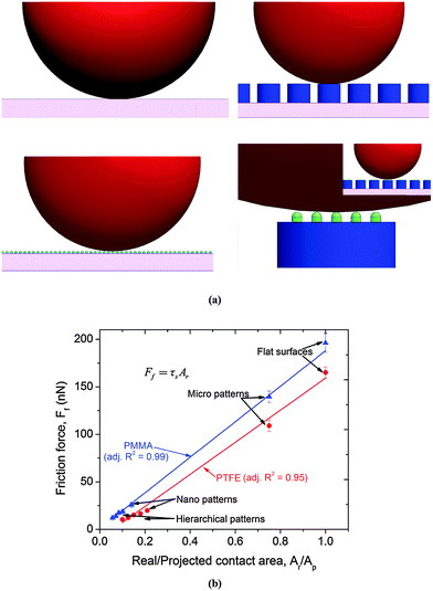 |
| | Fig. 7 (a) Contact between the indenter ball and the flat and patterned surfaces; (b) relationship between the friction force and the ratio of the real contact area to the projected contact area for the polymethylmethacrylate (PMMA) and polytetrafluoroethylene (PTFE) coated surfaces. The contact areas between the different geometric configurations were calculated using the Johnson–Kendall–Roberts (JKR) model. | |
Our results, which were in good agreement with earlier observations,28,29 indicated that the real area of contact determines the tribological behavior of the system. The friction force had a linear relationship with the ratio of the real contact area to the projected area (Fig. 7(b)). A similar linear trend between the friction force and the real contact area at the nano-scale was also reported by Enachescu et al.28 and discussed by Carbone and Bottiglione.29 According to the Bowden and Tabor model30 shown in eqn (13), the friction force (Ff) is directly proportional to the real area (Ar) of contact,
where
τs is the interfacial shear strength. In accordance with Derjagun's theory,
22 the friction force
Ff is a function of the normal load,
Fn, and the adhesion force,
Fa, expressed as
Ff =
μ(
Fn +
Fa). Thus, for a given normal load, the adhesion force, which is modulated by intermolecular and capillary forces, will determine the friction force (affecting the real area of contact), with high adhesion leading to an increase in the friction force.
Although the friction and adhesion forces decreased directly in relation to the increase in pitch due to the decrease in the real contact area, note that this scenario (when a spherical or conical shaped tip is used) is likely to be interrupted when the pitch increases beyond a critical limit. Beyond this critical value, the indenter will start intruding into the space between the geometries and eventually come in contact with the bottom flat surface.
4. Conclusions
Hierarchical patterns with different surface chemistries were fabricated, mimicking the topography of the lotus leaf. The patterned surfaces were designed to investigate the effect of the pitch between the nano-scale geometries on their wetting and tribological behaviors. For comprehensiveness, micro- and nano-patterns with similar geometric configurations and surface chemistries were also fabricated. The results showed a significant improvement in the tribological and wetting behaviors of the hierarchical patterns over that of their counterparts, i.e., micro- and nano-patterned and flat surfaces. The PTFE-coated hierarchical patterns showed advancing and receding angles similar to the real lotus leaf. The hierarchical patterns showed significant decreases in friction and adhesion compared with the flat and micro-patterned surfaces. Increasing the pitch of the nano-scaled geometry of the hierarchical patterns had a negligible effect on their wetting behaviors (advancing and receding angles), but the friction and adhesion were influenced significantly. Similarly, surface chemistry had an insignificant influence on the wetting of the hierarchical patterns, but it had a significant effect on the friction and adhesion performances. This influence of surface chemistry on friction and adhesion was linked to the intermolecular forces that determine the long-range van der Waals attractive and capillary forces. The effects of capillary forces on the adhesion and friction of the flat and patterned surfaces were verified experimentally. A change in relative humidity showed a significant influence on the adhesion and friction behavior of all the investigated surfaces. Furthermore, the improved tribological performances of the hierarchical patterns in comparison to the micro- and nano-patterns and flat surfaces were due to the reduction in the real area of contact, as highlighted by the contact mechanics analysis. This phenomenon was emphasized by the direct correlation between the friction force and the real contact area. Furthermore, in contrast to the single-asperity contact condition between the indenter and patterned surface predicted by the contact mechanics models, the consideration of the capillary forces originating from the condensed water vapor in the narrow confined spaces between the adjacent pillars and the indenter transformed the contact to a multi-asperity contact condition. This transition was also assisted by the persisting presence of the intermolecular van der Waals force due to the significantly minute gaps (a few nanometers) between the geometries. Thus, it was concluded that the intermolecular van der Waals force and the capillary force significantly modified the contact condition and must be taken into account when considering the tribological behavior of patterned surfaces.
Acknowledgements
This research was supported by the KIST Institutional Program (2E25590 and 2E25474) and the Original Technology Research Program for Brain Science through the National Research Foundation of Korea (NRF), which is funded by the Ministry of Education, Science, and Technology (NRF-2012M3C7A1055410).
References
- M. Nosonovsky and B. Bhushan, Mater. Sci. Eng., R, 2007, 58, 162–193 CrossRef.
- B. Zappone, K. J. Rosenberg and J. Israelachvili, Tribol. Lett., 2007, 26, 191–201 CrossRef CAS.
- M. Urbakh, J. Klafter, D. Gourdon and J. Israelachvill, Nature, 2004, 430, 525–528 CrossRef CAS PubMed.
- J. A. Williams and H. R. Le, J. Phys. D: Appl. Phys., 2006, 39, R201–R214 CrossRef CAS.
- B. Bhushan, Microelectron. Eng., 2007, 84, 387–412 CrossRef CAS.
- E. S. Yoon, R. A. Singh, H. Kong, B. Kim, D. H. Kim, H. E. Jeong and K. Y. Suh, Tribol. Lett., 2006, 21, 31–37 CrossRef CAS.
- R. Maboudian and C. Carraro, Annu. Rev. Phys. Chem., 2004, 55, 35–54, DOI:10.1146/annurev.physchem.55.091602.094445.
- D. C. Pham, K. Na, S. Piao, I. J. Cho, K. Y. Jhang and E. S. Yoon, Nanotechnology, 2011, 22, 395303, DOI:10.1088/0957-4484/22/39/395303.
- C. Poulard, F. Restagno, R. Weil and L. Léger, Soft matter, 2011, 7, 2543–2551, 10.1039/C0SM01099E.
- B. He, W. Chen and Q. Jane Wang, Tribol. Lett., 2008, 31, 187–197 CrossRef CAS.
- J. Sondhauß, H. Fuchs and A. Schirmeisen, Tribol. Lett., 2011, 42, 319–324 CrossRef.
- H. Zeng, N. Pesika, Y. Tian, B. Zhao, Y. Chen, M. Tirrell, K. L. Turner and J. N. Israelachvili, Langmuir, 2009, 25, 7486–7495 CrossRef CAS PubMed.
- L. Y. L. Wu, Q. Shao, X. C. Wang, H. Y. Zheng and C. C. Wong, Soft Matter, 2012, 8, 6232–6238 RSC.
- D. Ebert and B. Bhushan, J. Colloid Interface Sci., 2012, 368, 584–591 CrossRef CAS PubMed.
- K. Y. Suh, H. E. Jeong, D. H. Kim, R. A. Singh and E. S. Yoon, J. Appl. Phys., 2006, 100, 034303, DOI:10.1063/1.2222071.
-
B. Bhushan, Handbook of Micro/Nano Tribology, CRC Press, 2nd edn, 1999 Search PubMed.
- J. F. Oliver, C. Huh and S. G. Mason, J. Colloid Interface Sci., 1977, 59, 568–581 CrossRef CAS.
- A. Tuteja, W. Choi, M. Ma, J. M. Mabry, S. A. Mazzella, G. C. Rutledge, G. H. McKinley and R. E. Cohen, Science, 2007, 318, 1618–1622 CrossRef CAS PubMed.
- H. S. Grewal, I.-J. Cho, J.-E. Oh and E.-S. Yoon, Nanoscale, 2014, 6, 15321–15332 RSC.
- E. Arzt, S. Gorb and R. Spolenak, Proc. Natl. Acad. Sci. U. S. A., 2003, 100, 10603–10606 CrossRef CAS PubMed.
- D. R. King, M. D. Bartlett, C. A. Gilman, D. J. Irschick and A. J. Crosby, Adv. Mater., 2014, 26, 4345–4351 CrossRef CAS PubMed.
-
J. N. Israelachvili, Intermolecular and Surface Forces: Revised Third Edition, Elsevier Science, 2011 Search PubMed.
- K. L. Johnson and J. A. Greenwood, J. Colloid Interface Sci., 1997, 192, 326–333 CrossRef CAS PubMed.
- D. Maugis, J. Colloid Interface Sci., 1992, 150, 243–269 CrossRef CAS.
- D. Tabor, J. Colloid Interface Sci., 1977, 58, 2–13 CrossRef CAS.
- K. L. Johnson, K. Kendall and A. D. Roberts, Proc. R. Soc. London, Ser. A, 1971, 324, 301–313 CrossRef CAS.
- G. G. Adams and M. Nosonovsky, Tribol. Int., 2000, 33, 431–442 CrossRef.
- M. Enachescu, R. J. A. van den Oetelaar, R. W. Carpick, D. F. Ogletree, C. F. J. Flipse and M. Salmeron, Tribol. Lett., 1999, 7, 73–78 CrossRef CAS.
- G. Carbone and F. Bottiglione, J. Mech. Phys. Solids, 2008, 56, 2555–2572 CrossRef.
-
F. P. Bowden and D. Tabor, The Friction and Lubrication of Solids, Clarendon Press, Oxford, 1950 Search PubMed.
Footnotes |
| † Electronic supplementary information (ESI) available. See DOI: 10.1039/c5sm01649e |
| ‡ Both authors contributed equally. |
|
| This journal is © The Royal Society of Chemistry 2016 |
Click here to see how this site uses Cookies. View our privacy policy here.  Open Access Article


![[P with combining macron]](https://www.rsc.org/images/entities/i_char_0050_0304.gif) = P/πwR, to determine the model that is best suited for the particular contact condition. The transition parameters are functions of the theoretical stress σ0 = 1.03w/Z0, work of adhesion w, and equivalent radius R = [1/r1 + 1/r2]−1,
= P/πwR, to determine the model that is best suited for the particular contact condition. The transition parameters are functions of the theoretical stress σ0 = 1.03w/Z0, work of adhesion w, and equivalent radius R = [1/r1 + 1/r2]−1,


