
 Open Access Article
 This Open Access Article is licensed under a
 Creative Commons Attribution 3.0 Unported Licence
Micro-mechanics of nanostructured carbon/shape memory polymer hybrid thin film†
Ming
Lei‡
ab,
Ben
Xu‡
 b,
Yutao
Pei
c,
Haibao
Lu
*a and
Yong Qing
Fu
*b
b,
Yutao
Pei
c,
Haibao
Lu
*a and
Yong Qing
Fu
*b
aNational Key Laboratory of Science and Technology on Advanced Composites in Special Environments, Harbin Institute of Technology, Harbin 150080, People's Republic of China. E-mail: luhb@hit.edu.cn
bFaculty of Engineering and Environment, Northumbria University, Newcastle upon Tyne, NE1 8ST, UK. E-mail: Richard.fu@northumbria.ac.uk
cFaculty of Mathematics and Natural Sciences, Advanced Production Engineering – Engineering and Technology Institute Groningen, University of Groningen, Nijenborgh 4, 9747 AG Groningen, The Netherlands
First published on 1st October 2015
Abstract
This paper investigates the mechanics of hybrid shape memory polymer polystrene (PS) based nanocomposites with skeletal structures of CNFs/MWCNTs formed inside. Experimental results showed an increase of glass transition temperature (Tg) with CNF/MWCNT concentrations instead of a decrease of Tg in nanocomposites filled by spherical particles, and an increase in mechanical properties on both macro- and μm-scales. Compared with CNFs, MWCNTs showed a better mechanical enhancement for PS nanocomposites due to their uniform distribution in the nanocomposites. In nanoindentation tests using the Berkovich tips, indentation size effects and pile-up effects appeared obviously for the nanocomposites, but not for pure PS. Experimental results revealed the enhancement mechanisms of CNFs/MWCNTs related to the secondary structures formed by nanofillers, including two aspects, i.e., filler–polymer interfacial connections and geometrical factors of nanofillers. The filler–polymer interfacial connections were strongly dependent on temperature, thus leading to the opposite changing trend of loss tangent with nanofiller concentrations, respectively, at low and high temperature. The geometrical factors of nanofillers were related to testing scales, further leading to the appearance of pile-up effects for nanocomposites in the nanoindentation tests, in which the size of indents was close to the size of the nanofiller skeleton.
1. Introduction
Shape memory polymers (SMPs) can recover their original shapes from deformed states upon various external stimuli including heat, electric field, magnetic field and light, and their shape memory mechanism is based on reversible energy conversion in polymer chain movements, as shown in Fig. 1.1–6 The programmable shape memory ability of the SMPs has potential applications in sensors/actuators,7 biomedical devices8,9 and aerospace industries.10 Currently, great effort has been made to modify the existing SMPs for the improved mechanical, functional and shape memory properties by adding various nanofillers, aiming to overcome the low stiffness and strength of the pure SMPs, which remarkably limit the applications when compared to other shape memory materials such as shape memory alloys or ceramics.11–14 Both carbon nanofibers (CNFs) and carbon nanotubes (CNTs) received great attention recently as they can effectively improve both the mechanical and functional (such as electrical and optical) properties of the SMP matrix. For example, Leng et al.15 reported the novel infrared activating ability of shape memory nanocomposites with various carbon nanofillers. Ni et al.16 found a dramatic improvement in the macroscopic mechanical properties and shape recovery ability by adding CNTs inside shape memory polyurethane. Gunes et al.17 synthesized shape memory polyurethane based nanocomposites by adding carbon black and CNFs for the enhanced electrical properties and the electro-active recovery ratio. Jung et al.18 prepared carboxyl group modified CNT reinforced shape memory polyurethane nanocomposites by cross-linking polymerization, and achieved high-performance shape memory.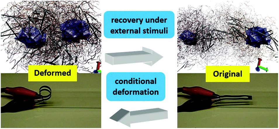 | ||
| Fig. 1 A schematic diagram of shape recovery of shape memory nanocomposites with rod/tube shape fillers. | ||
There are a lot of reports on the characterization of mechanical and shape recovery properties of the SMP nanocomposites, most of which focus on the macroscopic mechanical tests, such as tensile tests and dynamic thermomechanical analysis (DMA).19,20 Limited effort has been made to understand the nm-/μm-scale mechanical enhancement of those SMP nanocomposites. However, this micro-mechanism is essential to understand the enhancement mechanism, to grasp the stretch induced softening effect, and to utilize shape memory polymers/nanocomposites in micro-device applications.19–21 Nanoindentation is a well-known method for the nm-/μm-scale mechanical characterization of materials, which could be used to study the deformation of the reinforcement phase.22 Previous studies have been made on the nanoindentation of pure SMPs. For example, Wornyo et al.23 investigated the deformation behavior of diethylene glycol dimethacrylate and polyethylene glycol dimethacrylate shape memory copolymer networks with various organic components based on the nanoindentation results. Fulcher et al.24 provided a detailed approach on the thermomechanical characterization of a thermosetting epoxy based SMPs by nanoindentation tests at different temperatures. Nelson et al.25 reported a temperature-dependent nano-scale recovery of a thermosetting epoxy based SMPs using the tip of atomic force microscopy (AFM). However, only a few studies are available for the nanoindentation research on the SMP nanocomposites.26,27
As a further exploration of our previous studies on the thermal–mechanical properties and shape memory performance of nanocomposites reinforced by spherical particles,27,28 this study is focused on the micro-mechanics and the strengthening mechanism of polystyrene (PS) based CNF/MWCNT nanocomposites. A scanning electron microscope (SEM) was used to identify the micro-structures of CNF/MWCNT nanocomposites. Dynamic mechanical analysis (DMA) was used to determine the influence of nanofillers on thermal–mechanical properties of nanocomposites, and the nanoindentation tests were used to characterize the micro-mechanical properties. An atomic force microscope (AFM) was employed to quantitatively study the indents left by the Berkovich tips. Finally, theoretical analysis was done to understand the mechanical enhancement mechanism of CNFs/MWCNTs. This work is focused on the enhancement mechanism of CNFs/MWCNTs on shape memory polymers, which would be helpful for understanding the Mullins' effect,19,20 establishing constitutive equations29 and designing tunable wrinkle devices.30
2. Materials and experiments
As-received CNFs (PR-19-LHT-OX, average diameter = 100–200 nm, l/d = 150–1000, PYROGRAF Products Inc., USA) and multi-walled CNTs (MWCNTs, average diameter = 110–170 nm, l/d = 30–90, SIGMA, UK) were dried in an oven at 120 °C for 48 hours to remove the moisture. The nanofillers were dispersed in toluene (SIGMA, UK) with a surfactant, sodium dodecyl benzene sulfonate (SDBS, SIGMA, UK). The mixture was stirred ultrasonically at a speed of 1000 rpm for 6 hours. Then, a styrene-based precursor (styrene content ≥85 wt%) was added in the solution and the mixture was agitated ultrasonically for 3 hours at a rotational speed of 1000 rpm. Finally, a benzoyl peroxide based curing agent (Luperox ATC50, SIGMA, UK) was added and the mixture was stirred ultrasonically at 1000 rpm for another 1 hour. Film samples of SMP and nanocomposites with a thickness of 0.2 mm were casted into the PTFE mould and baked at 75 °C for 36 hours. Samples with exact shape were processed according to ASTM D638 for tensile testing.SEM (Tescan Lyra FIB/SEM-FEG) was used to observe the micro-structures of the nanocomposites. DMA tests were carried out in tension mode using a TA Instruments DMA 2980 at a frequency of 1 Hz with a default 0.1% peak to peak amplitude, a heating rate of 2 °C min−1, and a temperature range from 25 °C to 100 °C. Nanoindentation was carried out using a Tribo-Indenter system (Triboscope, Hysitron Inc., Minneapolis, USA) equipped with a standard diamond Berkovich tip. The measurements were taken at room temperature (∼20 °C). An acoustic enclosure was adopted to prevent the acoustic interferences from the environment. The indentation procedures were programmed into three steps, as shown in Fig. 2. The first step is to increase the load to a maximum value with a loading rate of 200 μN s−1, followed by a 5-second holding time at the maximum load. This load holding step was applied to minimize the effects of material creep on the estimated values of modulus and hardness, and to investigate the viscous effect on the nm-/μm-scale.31 The third step is to retrieve the indenter tip from the sample with an unloading rate of 200 μN s−1. Finally, two 2 × 2 arrays of indents were left on each sample.
 | (1) |
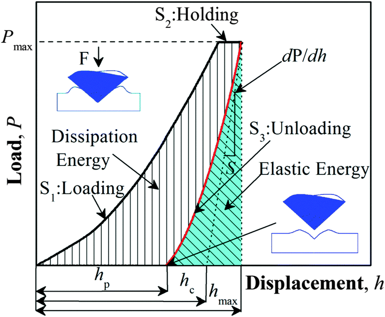 | ||
| Fig. 2 The typical load/unload–displacement curve for nanoindentation tests on shape memory nanocomposites. | ||
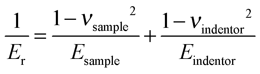
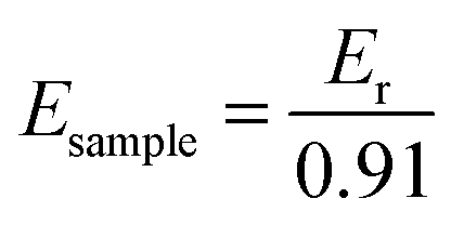
According to Oliver and Pharr,32–34 the calculation equation for the elastic modulus of the sample from nanoindentation tests with a Berkovich tip is eqn (1), and parameters used are listed in Table 1. Thus, the elastic modulus of the sample, Esample, can be calculated from eqn (2), where Er is the measured reduced modulus.
 | (2) |
| Parameter | Symbol | Expression | Value |
|---|---|---|---|
| Reduced modulus | E r |
|
Calculated |
| Unloading curve slope | S |
|
Measured |
| Contact area | A | A = 24.5hc2 | Calculated |
| Contact depth | h c |
|
Calculated |
| Max penetrating depth | h max | — | Measured |
| Max indentation force | Pmax | — | 1000 μN |
| Elastic modulus of tips | E indenter | — | 1140 GPa |
| Poisson's ratio of tips | ν indenter | — | 0.07 |
| Elastic modulus of samples | E sample | — | Calculated |
| Poisson's ratio of samples | ν sample | — | 0.31 |
The dissipation energy is defined as the enclosed area of the load–displacement curve which represents the absorbed energy in material, and the elastic energy is the area beneath the unloading curve which represents the recoverable energy, as shown in Fig. 2.23 AFM built in the nanoindentation system was employed to investigate the indentation imprint.
3. Results and discussion
3.1 Morphologies observed by SEM
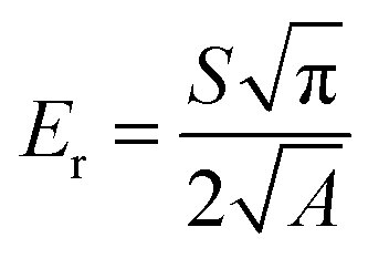
According to the product spreadsheets from the suppliers, the CNFs have a larger value of l/d and higher scattering of the diameter range compared with MWCNTs. Fig. 3 shows the SEM images of the nanocomposites with 2 wt% nanofillers. The CNFs mainly exist as irregular bundling states in the composites as shown in Fig. 3b. Tens even hundreds of individual CNFs form bundle structures, which could lead to the stress concentration and prevent the effective load transformation, thus resulting in deterioration of the mechanical enhancement.35 The random aggregation of CNFs based on the SEM observation will dramatically reduce the enhancement effects of the nanofillers by lowering the effective distribution of nanofillers, inducing defects in micro-structures and blocking load transformation. | ||
| Fig. 3 SEM images of the shape memory nanocomposites. (a) Irregular crossing distribution in the 2 wt% CNFs/PS composite system. (b) The CNF knots and interlocks in the selected area. (c) Uniform scattering of MWCNTs in the 2 wt% MWCNT/PS composite system. (d) The amplifying image of MWCNTs in the selected area. | ||
Compared with CNFs, MWCNTs showed a homogeneous dispersion inside the hybrid system as shown in Fig. 3c, which form uniform bundle structures. Under the same surfactant treatment, the better dispersion of MWCNTs is mainly due to its smaller ratio of l/d. Fig. 3d clearly reveals that the MWCNTs are pulled out from the polymer substrate. As shown in SEM images, the bundle structures of nanofillers form a skeleton inside the nanocomposites, which provides effective paths to transfer mechanical loads.
3.2 Results of DMA
The DMA results for all the samples are plotted in Fig. 4, which shows variations of storage modulus E′ and loss tangent tan![[thin space (1/6-em)]](https://www.rsc.org/images/entities/char_2009.gif) δ as functions of temperature. The storage modulus E′ and loss modulus E′′ (see Fig. S1, ESI†), respectively, represents the ability of materials to resist elastic and viscous deformation. The tanδ represents the damping effect, and its peak could indicate the glass transition temperature (Tg) of samples. As shown in Fig. S2 (ESI†), the Tg of composites measured by DMA tests increases rapidly with nanofiller concentrations from 60 °C to 75 °C, and an abnormal decrease appears in the 3 wt% CNF/PS nanocomposites, which is mainly due to the micro-defects introduced by the aggregates of CNFs. The Tg variation of nanocomposites strengthened by CNFs/MWCNTs is totally different from those nanocomposites filled by spherical particles, whose Tg decreases slightly with the nanofiller concentration as reported in our previous work.27 This phenomenon indicates that there is a strong filler–filler interaction for CNFs/MWCNTs inside the hybrid system.
δ as functions of temperature. The storage modulus E′ and loss modulus E′′ (see Fig. S1, ESI†), respectively, represents the ability of materials to resist elastic and viscous deformation. The tanδ represents the damping effect, and its peak could indicate the glass transition temperature (Tg) of samples. As shown in Fig. S2 (ESI†), the Tg of composites measured by DMA tests increases rapidly with nanofiller concentrations from 60 °C to 75 °C, and an abnormal decrease appears in the 3 wt% CNF/PS nanocomposites, which is mainly due to the micro-defects introduced by the aggregates of CNFs. The Tg variation of nanocomposites strengthened by CNFs/MWCNTs is totally different from those nanocomposites filled by spherical particles, whose Tg decreases slightly with the nanofiller concentration as reported in our previous work.27 This phenomenon indicates that there is a strong filler–filler interaction for CNFs/MWCNTs inside the hybrid system.
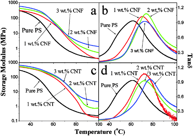 | ||
| Fig. 4 Thermal–mechanical properties of nanocomposites obtained from DMA tests. (a) E′ of CNF/PS composites. (b) tanδ of CNF/PS composites. (c) E′ of MWCNT/PS composites. (d) tanδ of MWCNT/PS composites. | ||
The DMA results characterize the macroscopic thermomechanical properties of shape memory nanocomposites, and will be discussed at both low temperature (Tl) and high temperature (Th), i.e., corresponding to the two operating temperatures in a standard shape memory programming procedure.4,27 To study thermal-mechanics and shape recovery of shape memory polymers/nanocomposites, previous researchers proposed a phenomenological approach to divide the SMP matrix into two phases, i.e., in the glassy state and rubbery state, and further assumed that the polymer matrix should be fully frozen into the glassy state at Tl and also fully activated into the rubbery state at Th.29,36 The thermomechanical properties of nanocomposites at Tl and Th determine their shape memory performances in the shape fixing step and in the shape recovery step. In this study, Tl and Th were set as 25 °C and 90 °C (∼Tg + 20 °C).
As shown in Fig. S3 (ESI†), the storage modulus E′ of these two types of nanocomposites at Tl increases with nanofiller concentrations, and reaches a maximum value of 711 MPa for the 3 wt% MWCNT/PS nanocomposites. Due to the softening effect of the polymer matrix, values of E′ decrease rapidly in the vicinity of Tg. At Th, values of E′ still increase with nanofiller concentrations, and then reach a maximum value of 3 MPa for the 3 wt% MWCNT/PS nanocomposites.
As shown in Fig. S4 (ESI†), loss modulus E′′ of MWCNT/PS nanocomposites at Tl increases with MWCNT concentrations and reaches a maximum value of 90 MPa. For CNF/PS nanocomposites, values of E′′ at Tl firstly decrease, and then increase with CNF concentrations, which is mainly due to the aggregates of CNFs inside the hybrid system. However, at ThE′′ values of these two types of nanocomposites increase with nanofiller concentrations, and reach a maximum value of 1.7 MPa for the 3 wt% MWCNT/PS nanocomposites.
Results of DMA tests reveal that MWCNTs have a better macroscale enhancement effect than CNTs, which could be attributed to the uniform distribution of MWCNTs, as shown in Fig. 3. Compared with the mechanical properties of the pure PS, the increase of storage modulus and loss modulus with filler concentrations indicates that the abilities of MWCNT/PS composites to resist both elastic deformation and creep deformation are strengthened by the addition of MWCNTs at both Tl and Th.
As shown in Fig. S5 (ESI†), values of loss tangent tanδ for these two types of nanocomposites decrease with nanofiller concentrations at Tl, but increase at Th. The hybrid system is composed of three components, i.e., the polymer matrix, nanofillers and the polymer–nanofiller interface. Because of the glass transition, the mechanical properties of the polymer matrix are strongly dependent on the temperature. However, the nanofillers with much higher moduli (∼500 GPa − 1 TPa) than the polymer matrix are usually treated as rigid bodies in studying filled rubber, and could be assumed to be independent of temperature.37 Thus, these two opposite trends of tanδ values varied with nanofiller concentrations at Tl and Th indicate that the polymer–nanofiller interfacial strength also depends on temperature.
The addition of nanofillers with high elastic modulus, on one hand improves the mechanical properties of pure PS, but on the other hand brings in the temperature dependent polymer–nanofiller interface. As revealed from Fig. S5 (ESI†), at Tl, the polymer–nanofiller interfacial connection is strong, and the addition of nanofillers reduces the damping effect of composites. However at Th, the polymer–nanofiller interfacial connection is weak, and the addition of nanofillers further increases the damping effect of composites.
Therefore, the enhancement effect of nanofillers is dependent on the synergistic influences of mechanical properties of nanofillers, nanofillers distributions, filler–filler interactions and the polymer–nanofiller interfacial strength. The variation of polymer–nanofiller interfacial strength with temperature and its influence on mechanical properties of polymer nanocomposites will be further discussed in Section 3.4.
3.3 Results of nanoindentation tests
Fig. 5 shows typical load–displacement curves for nanoindentation tests of the pure PS and PS based nanocomposites with 1 wt% CNFs and MWCNTs, respectively. Considering the pyramid geometry size of the Berkovich tip on the μm scale, the smooth curves indicate that there is no significant porosity in testing samples.38 The load–displacement curves for CNF/PS and MWCNT/PS samples show larger slopes of dP/dh in the unloading step and lower values of hmax compared with pure PS samples, reflecting the significant enhancement effect of nanofillers on micro-mechanical properties of nanocomposites. Furthermore, the increase in the penetration depth Δh during the load holding step is due to the viscous effect.39 Compared with that for the pure PS, adding MWCNTs significantly reduces the chain mobility of the polymer matrix, while CNFs slightly reduce the chain mobility. Similar to the results from the macroscale DMA tests, Fig. 5 reveals that MWCNTs have a better enhancing effect on the mechanical properties than CNFs on the μm scale, which could be attributed to several factors offered by MWCNTs, such as larger surface area and uniform dispersion. As a result, stable and uniform load transferring points are created inside the MWCNT/PS composites leading to a dramatic enhancement in the modulus/hardness.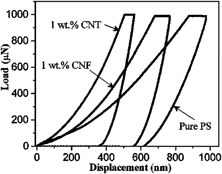 | ||
| Fig. 5 Load/unload–displacement curves of nanoindentation tests at room temperature (∼20 °C) under a max load of 1000 μN on three different samples, respectively, 1 wt% MWCNT/PS composite, 1 wt% CNF/PS and pure PS. | ||
The calculated values of hardness and elastic modulus as a function of indentation load are plotted in Fig. 6. An indentation size effect (ISE) is clearly observed as both hardness and modulus values decrease with increasing indentation loads (or indentation depth), before reaching a plateau. Fig. 6 also reflects that the ISE becomes more obvious with the increase of nanofiller concentrations. As reported in many articles, the ISE could be attributed to the intrinsic structures such as indentation elastic recovery and secondary structure.40–42 Here, considering no obvious ISE appearing in pure PS samples, the ISE could be mainly attributed to the secondary structure in the hybrid system.
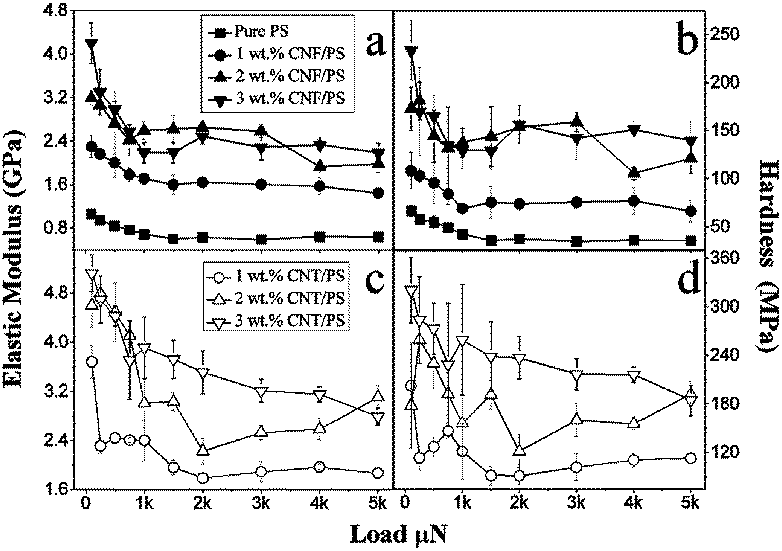 | ||
| Fig. 6 Experimental data from nanoindentation tests at room temperature (∼20 °C). (a) Elastic moduli of pure and CNF/PS composites. (b) Hardness of pure and CNF/PS composites. (c) Elastic moduli of MWCNT/PS composites. (d) Hardness of MWCNT/PS composites. | ||
Fig. 6 statistically confirms that the mechanical properties of PS polymers are improved by nanofillers, and enhancement effects of MWCNTs are better than CNFs. Under the 3 × 10⁻³ μN load for 3 wt% MWCNT/PS composites, the measured values of elastic modulus is 3.2 GPa showing about a 500% increase compared with pure PS, and the measured values of hardness is 230 MPa showing a 700% increase. Considering the working condition of nanoindentation and the secondary structures of this hybrid system, Berkovich tips would contact more nanofillers with the increase of filler concentrations, thus leading to an increase of measured modulus and hardness.22 In Fig. 6a and b, the measured curve of composites filled by 3 wt% CNFs is very close to those filled by 2 wt% CNFs, which indicates that enhancement effects of CNFs are weakened with nanofiller concentrations. This downward trend could be mainly attributed to the random aggregation of CNFs as revealed from Fig. 3.
Fig. 7a shows the calculated values of the dissipation energy in nanoindentation tests, which generally decrease with the increase of nanofiller concentrations. The dissipation energy, as a quantitative reflection of the viscous effect, is due to the internal friction or plastic deformation energy inside polymer/composites. Dissipation energy of the MWCNT/PS nanocomposites decreases continuously until the MWCNT concentration reaching 3 wt%. Furthermore, an abnormal increasing phenomenon is observed for the 3 wt% CNF/PS nanocomposites, as shown in Fig. 4, which is attributed to the obvious agglomeration of CNFs in nanocomposites.
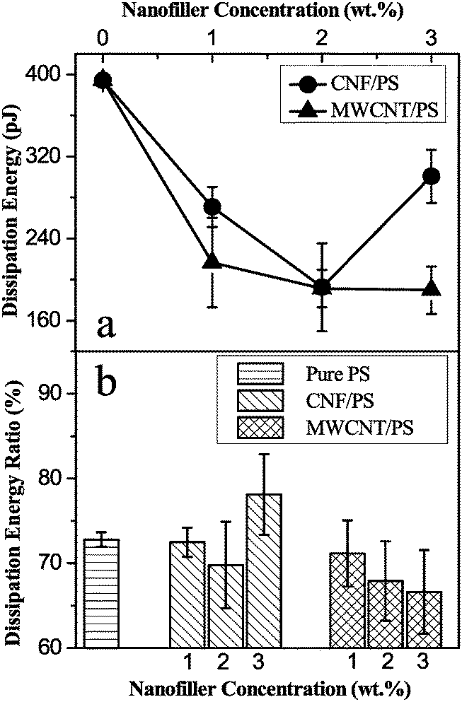 | ||
| Fig. 7 Elastic–plastic energy analysis based on nanoindentation results under a max load of 1000 μN. (a) Dissipation energy results. (b) Dissipation energy ratio. | ||
The varying trend of the dissipation energy with nanofiller concentrations in nanoindentation tests is coherent with that of the loss modulus E′′ in the DMA tests, both of which represent the ability of materials to resist viscous deformation. The DMA tests were conducted under strain control, but the nanoindentation tests were conducted under stress control. Thus, the increase of E′′ in DMA tests and the decrease of dissipation energy in nanoindentation tests reveal that the ability of nanocomposites to resist viscous deformation is strengthened by adding the nanofillers. The energy analysis further reveals that MWCNTs have a better enhancement effect than CNFs on the μm scale.
The pile-up effect, as a typical phenomenon for elastic–plastic materials in nanoindentation tests, describes the appearance of material accumulations besides the indent, which normally depends on the mechanical properties of the material, namely yielding stress, viscous effect and secondary structures.38,43,44 A critical ratio of E/σY (σY is the yield stress) was normally used to discuss the pile up effect, and this effect would become more apparent with the increase of the E/σY ratio.34,45 For the nanoindentation tests on the polymer based composites with a Berkovich tip, the corrected equations for the yield stress σY and pile-up effect are followed eqn (3)–(5),34,46,47 where c is the zone size of plastic deformation as demonstrated in Fig. 8b, a and b are constants related to the strain-hardening exponent, he is the elastic recovery depth, and hp is the plastic depth.
| σY = 0.25Pmaxc−2 | (3) |
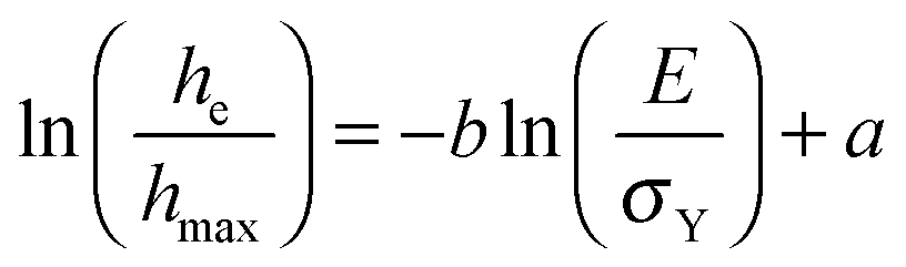 | (4) |
| he = hmax − hp | (5) |
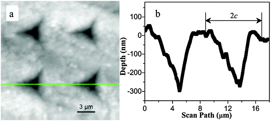 | ||
| Fig. 8 (a) AFM topographical image of a 2 × 2 array of indents left by a Berkovich tip in a PS surface under a max load of 2000 μN. (b) The plastic deformation zone of the cross-section profile along the line shown in Fig. 8a. | ||
There are two parameters obtained from nanoindentation results which are normally used to discuss the pile-up effects in metal and ceramic. The first parameter is the threshold value of E/σY = 90 which determines the onset of pile-up effects.45,48,49 The second one is the hp/hmax ratio. Oliver and Pharr (O&P) suggested that the pile-up effect was not obvious besides the indent if the ratio is below 0.7, which has been experimentally proved to be a constant regardless of the penetration depth.32,34 However, the previous studies showed that these two criteria for pile-up effects were no longer valid for polymers, whose mechanism is mainly due to the viscous effect.43,50Fig. 9 displays the statistical distributions of these two parameters for the nanocomposites. It is apparent that most of E/σY and hp/hmax ratios are within the threshold ranges, which means that there should be no apparent pile-up effect according to O&P criterion.
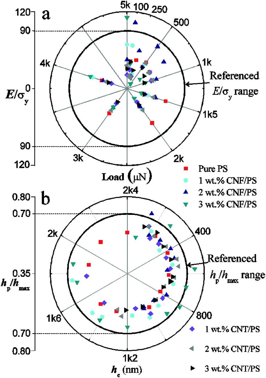 | ||
| Fig. 9 Statistical diagrams on the calculation result distribution of (a) E/σY as a function of load, (b) hp/hmax as a function of contact depth hc. | ||
However, Fig. 10b and c, i.e., AFM images of indents, provide visible evidence of surface morphologies, in which obvious pile-up edges besides the indent left by a Berkovich tip appeared on the nanocomposite surface, but no obvious pile-up edge was observed on the pure PS samples. It is clear that the O&P criterion is not valid for the polymer based nanocomposites in this study. From results of both DMA tests and nanoindentation tests shown in Fig. 4 and 7, the viscous effect of the pure PS is higher than those of the nanocomposites. Therefore, the pile-up effects of polymer based nanocomposites, which became more apparent by adding nanofillers, should be due to the contribution from the secondary structures of the hybrid system instead of the pure viscous effect.
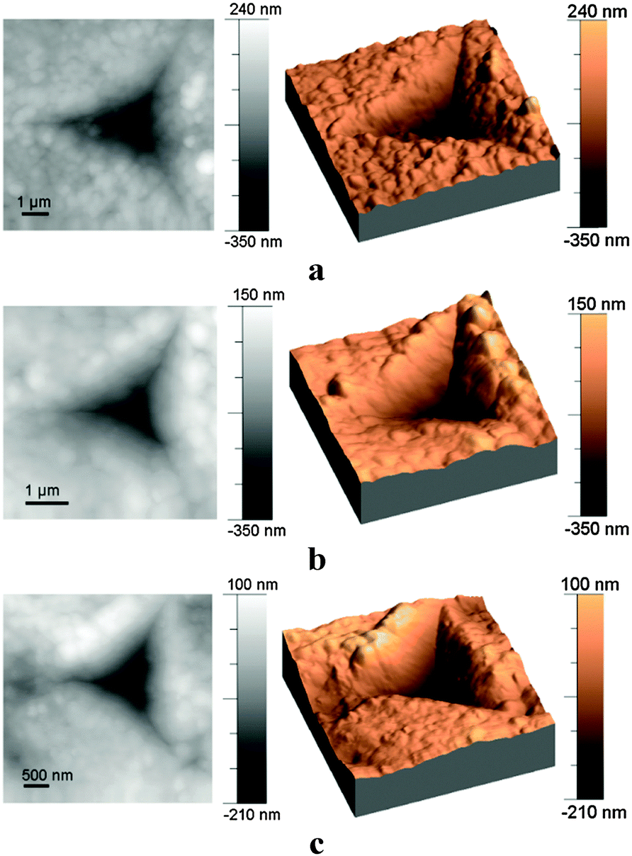 | ||
| Fig. 10 2D and 3D AFM images of surface deformation morphologies of indents left by a Berkovich tip under a max load of 2000 μN. (a) Pure PS. (b) 1 wt% CNF/PS composites. (c) 1 wt% MWCNT/PS composites. | ||
CNFs/MWCNTs enhance the mechanical properties of polymer nanocomposites, but could make their secondary structures discontinuous on the μm scale, thus leading to the appearance of ISE and the failure of O&P criterion for the pile-up effect, and this will be further discussed in the next section.
3.4 Microscale relative motions inside nanocomposites and enhancing mechanisms of nanofillers
According to the above experimental results, the macroscale and microscale performances of nanocomposites are both strongly dependent on the secondary structures of the hybrid system. The secondary structures formed by nanofillers are referred to two aspects, i.e., the filler–polymer interfacial connections and geometrical factors of nanofillers.The filler–polymer interfacial connections were thoroughly discussed while studying spherical particle filled rubber by Vilgis et al., which was described as the localization of chains in an energetic hole on the surface of nanofillers.37 This energetic hole determines the interfacial bonding strength, by which the interfacial connection is theoretically simplified as a viscous connection. The only difference in the shape memory nanocomposites with the rubber system is that the energetic hole is strongly dependent on the temperature instead of a constant, because its working mechanism relies on the glass transition of the polymer matrix.
The geometrical factors of CNFs/MWCNTs are more complicated. Previous research was mainly focused on the theoretical study of shape memory nanocomposites strengthened by spherical particles, which could be simplified as geometrical isotropic fillers, then using the basic assumption of equal stress in different phases.29,36 However, because of the large ratio of length and diameter, CNFs/MWCNTs inside the hybrid system have strong filler–filler interactions and form a skeletal micro-structure, leading to the failure of the these methods used in studying the spherical particle filled nanocomposites.
Herein, we try to use the view of microscale relative motions between nanofillers and the PS matrix to qualitatively analyse the mechanical performance and the enhancement mechanism of composites filled by CNFs/MWCNTs.
Fig. 11 shows a schematic diagram of the microscale relative motions between nanofillers and PS macromolecules. In addition to the skeletal network formed by CNFs/MWCNTs, another network is formed by PS macromolecules inside the hybrid system, therefore the local motion needs the participation of a long range of molecular chains. Considering that it is impossible for polymer molecules to pass through the polymer–filler interface, the addition of nanofillers would make the motion of molecules difficult, thus leading to a decrease in the chain mobility. Therefore, the enhancing mechanism of nanofillers depends on the synergistic effect of both filler–polymer interfacial connections and geometrical factors of nanofillers.
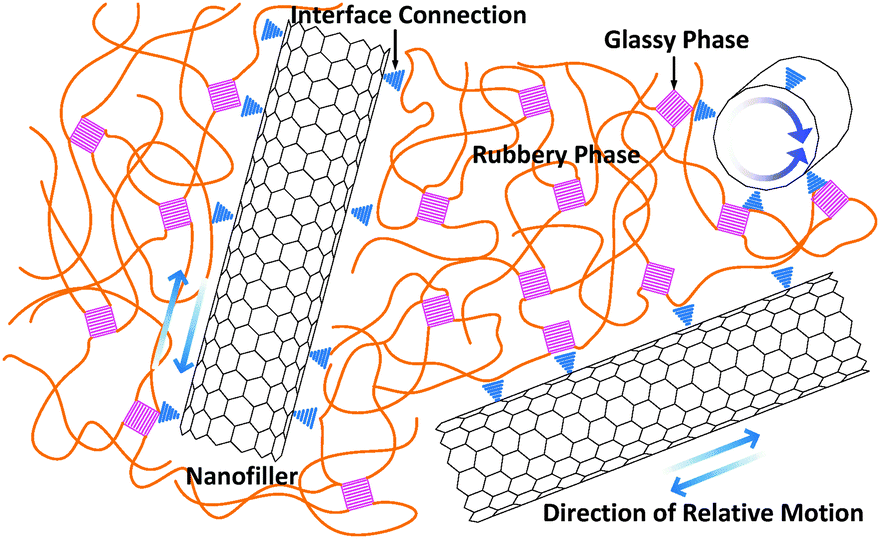 | ||
| Fig. 11 A schematic diagram of the relative microscale motions between nanofillers and the PS matrix. | ||
The restriction or enhancement effects of nanofillers on the motion of polymer molecules depends on the temperature, which causes the changes in filler–polymer interfacial strength. As shown in Fig. S5 (ESI†), the damping effect of nanocomposites decreases with nanofiller concentrations at Tl, but increases at Th. That phenomenon indicates that the energetic hole of chain localization on the filler surface is strongly dependent on temperature.
The restriction or enhancement effect of nanofillers on the motion of polymer molecules also depends on the length scale, which is achieved by geometrical factors of nanofillers. As shown in Fig. 3, inside the nanocomposites, CNFs/MWCNTs form a skeleton due to the strong filler–filler interactions. Therefore, there are two types of networks in the hybrid system, a polymer network and a filler network. The restriction effect of nanofillers works, only if the testing scale is much larger than the size of the filler network. However, for nanoindentation tests, the size of indents (4–6 μm) is very close to the size of nanofiller networks (about 1–5 μm), as shown in Fig. 3 and 8, respectively. Thus, the addition of nanofillers only hinders the long range motion of polymer chains, without affecting their local motions, which further leads to the appearance of the pile-up edge beside the indents when the measured modulus and hardness are both increased.
4. Conclusions
In this paper, the CNF/MWCNT PS based nanocomposites were fabricated and their micro-mechanics and enhancement mechanisms were experimentally investigated.SEM images reveal the skeleton formed by CNFs/MWCNTs in the SMP nanocomposites. Experimental results reflect a better enhancement effect of MWCNTs than CNFs. As reflected in DMA tests, the glass transition temperature of nanocomposites enhanced by CNFs/MWCNTs is significantly increased by nanofiller concentrations from 60 °C to 75 °C, and this trend is totally different for those of the nanocomposites filled by spherical particles. The addition of nanofillers can lead to an increase in the mechanical properties of nanocomposites, except for 3 wt% CNF/PS composites. The storage modulus and loss modulus of nanocomposites both increase with nanofiller concentrations at Tl (25 °C) and Th (90 °C). However, the loss tangent decreases with nanofiller concentrations at Tl, but increases at Th. As reflected in nanoindentation tests, the addition of nanofillers leads to an increase in hardness and modulus of the materials on the μm scale. In indentation tests by the Berkovich tips, the indentation size effect and the pile-up effect both obviously appear in nanocomposites, but not in those of pure PS.
Theoretical analysis shows that mechanical properties and enhancement mechanisms of nanocomposites are both strongly dependent on their secondary structures, which could be further divided into the filler–polymer interfacial connection and geometrical factors of nanofillers. The filler–polymer interfacial connection, which is due to the localization of polymer chains on the surface of nanofillers, relies on the temperature. The high energetic hole at Tl and low energetic hole at Th of polymer chain localization lead to the opposite trends of loss tangent with nanofiller concentrations at Tl and at Th. The geometrical factors of CNFs/MWCNTs are due to the large ratio of length and diameter, and the enhancement effects of nanofillers on the motion of polymer molecules only work when the testing scale is larger than the size of the filler networks. Because in the nanoindentation tests, the size of indents (4–6 μm) is very close to the size of the nanofiller networks (about 1–5 μm), the pile-up effects are obvious in the nanocomposites compared with those in the pure PS, further leading to the failed prediction from the O&P criterion for the polymer based nanocomposites.
Acknowledgements
The authors acknowledge the financial support from Royal Academy of Engineering-Research Exchanges with China and India Awards and UoA flexible fund from Northumbria University at Newcastle upon Tyne, the National Natural Science Foundation of China (NSFC) under Grant No. 11422217. Ben would like to thank the support from EU-COST, RSC and REECE INNOVATION. The authors also acknowledge the help of the anonymous reviewers, whose insightful comments and advices greatly improved this paper.References
- B. S. Lee, B. C. Chun, Y. C. Chung, K. I. Sul and J. W. Cho, Macromolecules, 2001, 34(18), 6431–6437 CrossRef CAS.
- B. Xu, W. M. Huang, Y. T. Pei, Z. G. Chen, A. Kraft, R. Reuben, J. T. M. D. Hosson and Y. Q. Fu, Eur. Polym. J., 2009, 45(7), 1904–1911 CrossRef CAS.
- X. F. Luo and P. T. Mather, Soft Matter, 2010, 6(10), 2146–2149 RSC.
- Q. Zhao, H. J. Qi and T. Xie, Prog. Polym. Sci., 2015, 49–50(10–11), 79–120 CrossRef CAS.
- A. Lendlein, H. Jiang, O. Jünger and R. Langer, Nature, 2005, 434(7035), 879–882 CrossRef CAS PubMed.
- H. B. Lu, M. Lei, Y. T. Yao, K. Yu and Y. Q. Fu, Nanosci. Nanotechnol. Lett., 2014, 6(9), 772–786 CrossRef.
- H. B. Lu, M. Lei, C. Zhao, B. Xu, J. Leng and Y. Q. Fu, Smart Mater. Struct., 2015, 24(4), 045015 CrossRef.
- I. V. Ward Small, P. Singhal, T. S. Wilson and D. J. Maitland, J. Mater. Chem., 2010, 20(17), 3356–3366 RSC.
- J. Reeder, M. Kaltenbrunner and T. Ware, et al. , Adv. Mater., 2014, 26(29), 4967–4973 CrossRef CAS PubMed.
- J. Leng, X. Lan, Y. Liu and S. Du, Prog. Mater. Sci., 2011, 56(7), 1077–1135 CrossRef CAS.
- T. Xie, Nature, 2010, 464(7286), 267–270 CrossRef CAS PubMed.
- H. B. Lu and W. M. Huang, Appl. Phys. Lett., 2013, 102(23), 231910 CrossRef.
- Z. He, N. Satarkar, T. Xie, Y. T. Cheng and J. Z. Hilt, Adv. Mater., 2011, 23(28), 3192–3196 CrossRef CAS PubMed.
- I. S. Gunes, F. Cao and S. C. Jana, Polymer, 2008, 49(9), 2223–2234 CrossRef CAS.
- J. Leng, H. B. Lu, Y. Liu and S. Du, J. Appl. Phys., 2008, 104(10), 104917 CrossRef.
- Q. Q. Ni, C. Zhang, Y. Fu, G. Dai and T. Kimura, Compos. Struct., 2007, 81(2), 176–184 CrossRef.
- I. S. Gunes, G. A. Jimenez and S. C. Jana, Carbon, 2009, 47(4), 981–997 CrossRef CAS.
- Y. C. Jung, H. J. Yoo, Y. A. Kim, J. W. Cho and M. Endo, Carbon, 2010, 48(5), 1598–1603 CrossRef CAS.
- T. Ohki, Q. Q. Ni, N. Ohsako and M. Iwamoto, Composites, Part A, 2004, 35(9), 1065–1073 CrossRef.
- K. Yu, Q. Ge and H. J. Qi, Polymer, 2014, 55(23), 5938–5947 CrossRef CAS.
- C. C. Fu, A. Grimes, M. Long, C. G. Ferri, B. D. Rich, S. Ghosh, L. P. Lee, M. Gopinathan and M. Khine, Adv. Mater., 2009, 21(44), 4472–4476 CrossRef CAS.
- H. J. Qi, K. B. K. Teo, M. C. Boyce, W. I. Milne, J. Robertson and K. K. Gleason, J. Mech. Phys. Solids, 2003, 51(11), 2213–2237 CrossRef CAS.
- E. Wornyo, K. Gall, F. Yang and W. King, Polymer, 2007, 48(11), 3213–3225 CrossRef CAS.
- J. T. Fulcher, Y. C. Lu, G. P. Tandon and D. C. Foster, Polym. Test., 2010, 29(5), 544–552 CrossRef CAS.
- B. A. Nelson, W. P. King and K. Gall, Appl. Phys. Lett., 2005, 86(10), 103108 CrossRef.
- F. Li and R. C. Larock, Biomacromolecules, 2003, 4(4), 1018–1025 CrossRef CAS PubMed.
- B. Xu, Y. Q. Fu, M. Ahmad, J. K. Luo and W. M. Huang, J. Mater. Chem., 2010, 20(17), 3442–3448 RSC.
- B. Xu, L. Zhang, Y. T. Pei, J. K. Luo, S. W. Tao, J. T. M. De Hosson and Y. Q. Fu, Nanosci. Nanotechnol. Lett., 2012, 4(8), 814–820 CrossRef CAS.
- M. Baghani, R. Naghdabadi, J. Arghavani and S. Sohrabpour, Int. J. Plast., 2012, 35, 13–30 CrossRef CAS.
- B. Xu, D. Chen and R. C. Hayward, Adv. Mater., 2014, 26(25), 4381–4385 CrossRef CAS PubMed.
- T. Chudoba and F. Richter, Surf. Coat. Technol., 2001, 148(2), 191–198 CrossRef CAS.
- W. C. Oliver and G. M. Pharr, J. Mater. Res., 1992, 7(06), 1564–1583 CrossRef CAS.
- K. C. Maner, M. R. Begley and W. C. Oliver, Acta Mater., 2004, 52(19), 5451–5460 CrossRef CAS.
- W. C. Oliver and G. M. Pharr, J. Mater. Res., 2004, 19(01), 3–20 CrossRef CAS.
- J. N. Coleman, U. Khan, W. J. Blau and Y. K. Gun'ko, Carbon, 2006, 44(9), 1624–1652 CrossRef CAS.
- Y. Liu, K. Gall, M. L. Dunn, A. R. Greenberg and J. Diani, Int. J. Plast., 2006, 22(2), 279–313 CrossRef CAS.
- T. A. Vilgis, G. Heinrich and M. Klüppel, Cambridge University Press, 2009, vol. 9–10, pp. 118–195.
- X. D. Li, H. S. Gao, W. A. Scrivens, D. L. Fei, X. Y. Xu, M. A. Sutton, A. P. Reynolds and M. L. Myrick, Nanotechnology, 2004, 15(11), 1416 CrossRef CAS.
- M. L. Oyen and R. F. Cook, J. Mater. Res., 2003, 18(01), 139–150 CrossRef CAS.
- A. Iost and R. Bigot, J. Mater. Sci., 1996, 31(13), 3573–3577 CAS.
- I. Manika and J. Maniks, Acta Mater., 2006, 54(8), 2049–2056 CrossRef CAS.
- C. S. Han and S. Nikolov, J. Mater. Res., 2007, 22(6), 1662–1672 CrossRef CAS.
- D. Tranchida, S. Piccarolo, J. Loos and A. Alexeev, Macromolecules, 2007, 40(4), 1259–1267 CrossRef CAS.
- F. Bedoui, F. Sansoz and N. S. Murthy, Acta Mater., 2008, 56(10), 2296–2306 CrossRef CAS.
- A. Bolshakov and G. M. Pharr, J. Mater. Res., 1998, 13(04), 1049–1058 CrossRef CAS.
- B. Du, O. K. Tsui, Q. Zhang and T. He, Langmuir, 2001, 17(11), 3286–3291 CrossRef CAS.
- X. Chen and J. J. Vlassak, J. Mater. Res., 2001, 16(10), 2974–2982 CrossRef CAS.
- Y. Q. Fu, C. Shearwood, B. Xu, L. G. Yu and K. A. Khor, Nanotechnology, 2010, 21(11), 115707 CrossRef CAS PubMed.
- Q. Zia, R. Androsch, H. J. Radusch and S. Piccarolo, Polymer, 2006, 47(24), 8163–8172 CrossRef CAS.
- J. L. Loubet, J. M. Georges and G. Meille, Microindentation techniques in materials science and engineering, ASTM STP, 1986, 889, 72–89 Search PubMed.
Footnotes |
| † Electronic supplementary information (ESI) available. See DOI: 10.1039/c5sm01269d |
| ‡ These authors contributed equally to this work. |
| This journal is © The Royal Society of Chemistry 2016 |