Polydimethylsiloxane bilayer films with an embedded spontaneous curvature†
A. I.
Egunov
a,
J. G.
Korvink
b and
V. A.
Luchnikov
*a
aInstitut de Science des Matériaux de Mulhouse, UMR 7361 CNRS-UHA, 15 rue Jean Starcky, 68057 Mulhouse, France. E-mail: valeriy.luchnikov@uha.fr
bKarlsruhe Institute of Technology, Institute of Microstructure Technology, Hermann von Helmholtz Platz 1, 76344 Eggenstein-Leopoldshafen, Germany. E-mail: jan.korvink@kit.edu
First published on 29th October 2015
Abstract
Elastomer polydimethylsiloxane (PDMS) films with embedded in-plane gradient stress are created by making PDMS/(PDMS + silicone oil) crosslinked bilayers and extracting the oil in a suitable organic solvent bath. The collapse of the elastomer after oil extraction generates differential stress in the films that is manifested through their out-of-plane deformation. The curvature κ of narrow stripes of the bilayer, which is composed of layers of approximately equal thicknesses and elasticity moduli, is satisfactorily described by the simple relationship κ = 1.5δH−1, where δ is the mechanical strain, and H is the total thickness of the bilayer. Curvature mapping of triangular PDMS plates reveals the existence of spherical and cylindrical types of deformation at different locations of the plates. Various 3D-shaped objects can be formed by the self-folding of appropriately designed 2D patterns that are cut from the films, or by nonuniform distribution of the collapsing layer. Thin PDMS bilayers with embedded stress roll up into microtubes of almost perfect cylindrical shape when released in a controlled manner from a substrate.
1. Introduction
Residual mechanical stress in thin solid films gives rise to a number of interesting phenomena, such as buckling or wrinkling of films that are attached to compliant substrates. When the in-plane stress is not homogeneous across the film's thickness, the resulting internal bending moment causes effects that include the spontaneous curvature of free-standing films. A good example of what this looks like can be seen from fallen leaves of certain tree species1 which curl up due to differential contraction of the drying leaf tissues.2 The vertical gradient of in-plane stress often arises in different types of artificial films. Thus, epitaxially grown semiconductor heterofilms develop the gradient due to the misfit of crystal lattice parameters on the top and bottom layers.3–7 In bimetallic Cr/Cu strips, produced by a thermal evaporation approach, a reversible strain is generated in the course of oxidation/reduction cycles of the Cu layer.8 In polymer films, a spontaneous curvature can be induced by unequal swelling of chemically distinct top and bottom layers in a suitable solvent.9–15 For instance, in the polystyrene/poly(4-vinyl pyridine) bilayers that are immersed in acidic water, curling occurs because of the selective swelling of the poly(4-vinyl pyridine) layer.9,14 The bending moment can also be generated in gradient-crosslinked homopolymer films, due to the dependence of the degree of swelling on the crosslinking density.15 Curling of trace paper stripes16,17 and polydimethylsiloxane (PDMS) beams18 was induced by non-homogeneous swelling of these materials, exposed at one side to a solvent (water and hexane, respectively). Temperature-responsive shape change was achieved for bilayer elastomers,13,19 comprising of an active layer of either the poly(N-isopropyl-acrylamide) hydrogel,13 or a liquid crystal elastomer.19 In the former case, the stress is induced by the reversible phase transition of the hydrogel above 32 °C from a swollen hydrated state to a shrunken dehydrated state. In the latter case, the temperature induced transition between the nematic and the disordered phase is accompanied by the uniaxial extension or the contraction of the active layer. Light can be used as an external stimulus, allowing to relax mechanical stress in a light-activated polymer layer, and thus to control the curvature of polymer laminate multilayer composites.20 Electrical control of the bilayer curvature can be effected via the volumetric response of the active layer to Joule heating,21 or due to electrochemical oxidation and reduction volume change of conjugated polymers.22 Finally, the curvature can be embedded in elastomeric films by a straightforward approach, which consists in the side-by-side gluing of elongated and unstrained films.23Recently, the spontaneous or stimulus-induced curling of bilayer films has attracted much attention as a phenomenon underlying an original method of the microfabrication of 3D micro- and nanoarchitectures from 2D structured films. Rolling-up epitaxially grown semiconductor heterofilms was explored for the design of micro-syringes for intracellular microinjections,3 optical resonators,4 radial superlattices and nanoreactors,5 tubular compartments for controlled neurite growth,6 and ultracompact components for on-chip capture and detection of individual micro-organisms.7 Temperature-stimulated swelling and deswelling of an active hydrogel layer were utilised for the controlled encapsulation and release of microparticles and living cells from microcontainers.13 Curling of partially oxidized PDMS films in chloroform vapour allowed for the engineering of a microfluidic device combined with a rolled-up electrical circuit.12
The spontaneous curvature of solid films gives rise to non-trivial effects such as the transition from spherical to elliptical deformation modes, which are characterized by the bifurcation of the spontaneous curvature when the internal bending moment or the film plate size reaches a critical value.18,24–29 This nonlinear geometrical effect is interesting both from theoretical and practical points of view because it needs to be understood and taken into account for the reliable design of micro-objects that are formed by a strain-driven self-assembly. Progress in this field could greatly benefit from the existence of simply fabricated elastic films with thickness variable in large ranges (from a few microns to millimetres) and with a spontaneous curvature that can be defined at the moment of the films’ fabrication. Such films could be convenient both for experimental studies on nonlinear geometrical effects like curvature bifurcation, and for the macroscopic modelling of self-folding of 2D-patterns into 3D objects. In this paper, we introduce PDMS films that correspond to these requirements. The permanent spontaneous curvature is achieved due to the specific bilayer architecture of the films, in which one of the layers is prepared initially with the controlled stoichiometric addition of silicone oil that acts as a molecularly dispersed filler. The extraction of the oil in a suitable organic solvent, such as chloroform or 2-propanol, leads to the collapse of the upper elastomer. The in-plane shrinkage is opposed by the underlying second film layer. This gives rise to a gradient of built-in stress and the out-of-plane deformation of the film. The degree of embedded stress is controlled by the volume fraction of oil in the composition of the top layer.
2. Results and discussion
2.1 Film fabrication and the bilayer beam curvature
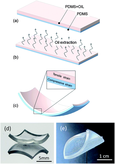
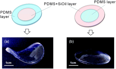
PDMS films with a spontaneous curvature were prepared according to the fabrication scheme illustrated in Fig. 1a–c. The bilayer film, its top layer containing silicone oil, was immersed in a chloroform bath to allow the oil to diffuse out of the elastomer. For the films whose thicknesses did not exceed 2 mm, stationary extraction was achieved within 48 hours (Fig. S1a, ESI†). The film was then dried for a few hours at room temperature to eliminate the solvent before further manipulation. The elastomer tends to restore its density after oil extraction and drying, at which point it collapses onto itself. The relative reduction of linear dimensions can be estimated as δ = 1 − (1 − x)1/3, where x is the volume fraction, x = Voil/(Voil + Vpdms), of oil in the film before extraction. For instance, for x = 0.5, the theoretical value of the dimension reduction is δ = 0.21. This is somewhat lower than the experimentally observed relative length contraction, δexp = 0.22 (Fig. S2, ESI†). This discrepancy may be explained by the fact that some PDMS chains may not be included in the polymer network and are thus also extracted in the solvent bath. Indeed, oil-free PDMS samples (x = 0) were subject to a 1–2% contraction after immersion in the chloroform bath. The volume fraction of oil in the composition cannot exceed approximately x = 0.6, because above this value the polymer is excessively diluted in the oil and does not form a continuous elastomer in the course of crosslinking. In most of our experiments, the oil fraction is within the limits of 0 ≤ x ≤ 0.5. Under these conditions, crosslinking results in sufficiently firm films.When the oil-containing PDMS layer is formed above the oil-free PDMS layer, the combination of strong adhesion between the layers, and the collapse of the top layer after oil extraction, creates the vertical gradient of the in-plane strain and bending moment in the bilayer films, which leads to their out-of-plane deformation. For a sufficiently small film plate, or small strain, the film acquires the shape of a spherical segment (Fig. 1d) with a unique isotropic curvature, κ = R−1 (R is the radius of curvature). Increasing the strain or dimensions of the film eventually leads to the bifurcation of the film curvature, allowing the film to accommodate a more energetically favourable configuration.18,24–29 With one of the principal curvatures growing and the other one diminishing, sufficiently large films take on a cylindrical conformation (Fig. 1e). The position of the bifurcation point depends not only on the strain and dimensions of the sample but also on the sample's shape. For instance, for a rectangular plate, it depends on the width-to-length ratio of the plate.28
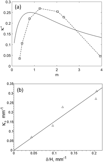
The bifurcation behavior of the PDMS films with an embedded spontaneous curvature will be discussed below in Section 2.5. Here, we consider the case of bilayer beams (Fig. S3, ESI†). For the beams, the geometrical constraints, which are at the origin of the bifurcation effects, do not intervene and the bilayer is characterized by a unique curvature radius, which we have measured by fixing the thickness of the bottom layer, h1 and varying the thickness of the top layer, h2 (Table 1). According to the Timoshenko beam theory,30 the curvature is estimated by the formula
 | (1) |
 | (2) |
| h 1, mm | 0.32 | 0.33 | 0.33 | 0.33 | 0.31 | 0.32 | 0.32 |
| h 2, mm | 0.11 | 0.15 | 0.26 | 0.41 | 0.63 | 0.74 | 1.25 |
| R, mm | 28.7 | 10.5 | 6.2 | 6.4 | 8.6 | 10.8 | 80 |
| κ, mm−1 | 0.034 | 0.095 | 0.161 | 0.156 | 0.116 | 0.093 | 0.013 |
Analysis of the function F(n,m) provides valuable information on the optimal composition of the bifilms. The function has the global maximum Fmax = 0.25 at n = 1, m = 1. This means that the bilayer has the maximal curvature when its components have equal elastic moduli and equal thicknesses. The maximum is fairly flat (see Fig. S4, ESI†): the function differs from its maximal value by a mere few percent when its arguments are within a relatively broad vicinity of the maximum position. For instance, F(0.5,1) = F(2,1) = 0.242…, which is only 3% smaller than the maximum value. This is an important fact because it means that the curvature is rather insensitive to the differences in the elastic moduli of the layers if these moduli are approximately equal. The function is somewhat more susceptible to the deviation of the thickness ratio m from the extreme value (a 12% decrease from a twofold change of the argument). Still, if the layers have approximately the same thicknesses and elastic moduli, the curvature can be estimated as
 | (3) |
2.2 Kirigami of the surfaces with a spontaneous curvature
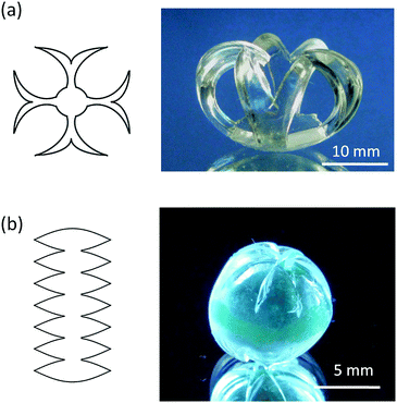
Cutting patterns from a film with a spontaneous curvature and allowing it to relax its mechanical energy can be explored for the formation of a multitude of 3D shapes. This process resembles the ancient art of paper cutting and folding, kirigami.31 However, in this case, the pattern on a surface with an embedded curvature takes its volumetric aspect from bending rather than folding. Two examples of 2D patterns and their corresponding 3D forms are shown in Fig. 3. A cage-like (or crown-like) form arises from a star-like pattern (Fig. 3a). All parts of the pattern are small enough, in at least one dimension, that they do not undergo bifurcation of the curvature upon energy relaxation. To a first approximation, one can consider the 3D cage form as part of a spherical surface. More accurate analysis will reveal that this sphere is not perfect, however, because the central disc has a lower curvature than the narrow arms of the star, due to geometrical constraints. Another example is the self-folding of a specific 2D pattern into a sphere (Fig. 3b). Such spheres may have some practical interest when scaled down and exploited as containers for living cells13 or for drug delivery applications. Suppose that the spontaneous curvature radius of the surface is R; then a sphere is formed by relaxing the pattern, which consists of N equal segments (N is an odd number), whose boundaries are given by | (4) |
2.3 Programming 3D objects via inhomogeneous distribution of the PDMS/silicon oil layer
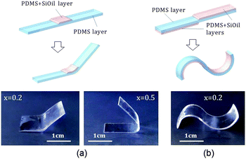
The shape of 3D objects can be programmed not only via specific arrangement of cuts of a uniform bilayer film, but also via an inhomogeneous distribution of the PDMS + silicon oil layer over the PDMS layer. For instance, a PDMS beam can be programmed to bend at specific locations by the creation of localized patterns of the PDMS + SiOil, as shown in Fig. 4a. The degree of bending can then be set up by the fraction x of oil in the pattern. Obviously, the angle α of bending can be controlled also by the length l of the PDMS + SiOil patch, α = κl, where κ is the curvature of the bilayer beam. Moreover, the direction of bending can be alternated by the formation of PDMS + SiOil stacks on different sides of the PDMS film (Fig. 4b).Uneven distributions of the in-plane stress in the film can lead to interesting curvature effects even without formation of the bilayer structure, as was noted for locally growing or shrinking elastic sheets.32–34Fig. 5a illustrates a saddle surface, which arises by oil extraction from a PDMS + SiOil disc, surrounded by a PDMS belt. If, in contrast, a PDMS + SiOil ring is formed on the periphery, and the central disc is made of PDMS, oil extraction leads to bumping of the central part, forming a spherical surface (Fig. 5b). Note that this structure is bistable, since the bulge can be flipped in the normal direction.
2.4 PDMS microtubes
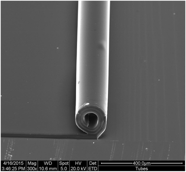
Scaling down the thickness of the bilayer PDMS films with an embedded curvature can be used for the microfabrication of 3D micro-structures from the material. As pointed out in the Introduction, microtubes formed by rolling-up strained films are of particular interest for a number of advanced applications. Earlier, we obtained PDMS microtubes via directional rolling of oxidized elastomer films in chloroform vapor.12 The quality of the tubes obtained by this approach is compromised by cracking in the oxide layer. Also, the use of chloroform or another organic solvent in the course of tube formation is not always convenient and limits the range of applications for the tubes (for instance, for biology). The use of films with a spontaneous bending moment, induced during their preparation, permits these drawbacks and limitations to be easily circumvented. Thin bilayer PDMS/(PDMS + oil) films were prepared on glass slides covered by a thin gelatine layer, as described in the experimental section. The gelatine layer retains the films on the glass substrate when they are dry, but allows the films to curl when the sample is immersed in water due to the dissolution of gelatine. The extracting agent 2-propanol was chosen for oil because it induces less swelling of PDMS (21% increase in linear dimension as compared to 39% for chloroform35), which avoids the delamination of the films from the substrate during the course of extraction. Oil extraction in the 2-propanol bath is considerably slower than in the chloroform bath (see Fig. S1b, ESI†). But because the characteristic diffusion time is proportionate to the square of the linear dimension of a sample, and PDMS films were thin in this set of experiments (H ≈ 17 μm), a few hours of extraction time is largely sufficient for eliminating oil from the composition. Release of the PDMS films results in tubes of almost perfect cylindrical shape (Fig. 6). The inner diameter of the tubes is of the order of 50–100 μm, and can be varied either by the thickness of the films or by the strain, that is, the oil concentration in the second layer before extraction. Prior to rolling, the films can be exposed to various surface treatment techniques, chemical activation, and pattern formations,9,14 which makes the tubes of interest to a multitude of applications in microfluidics and related fields.It is important to note that the temperature of the water bath influences the rate of dissolution of the sacrificial gelatine layer, and, therefore, the rate of a tube's formation. Thus, in a fixed time interval t = 1 min, the tubes form different numbers or revolutions, resulting in tubes of varying external diameter, Dex (Table 2), due to the different number of shells. For T = 20 °C, a tube is formed by approximately 1.5 shells, and for T = 85 °C, it has 3.25 shells (see Fig. S6, ESI†). The inner diameter of the tubes, Din, does not depend on the water temperature bath, because it is determined by the curvature of the PDMS bilayer. The consecutive layers are apparently bound to each other by the van der Waals forces, which explains why the layers do not slide along each other, and the inner diameter does not diminish under the pressure of the outer layers, whose curvature differs from the equilibrium value.
| T, °C | D in, μm | D ex, μm |
|---|---|---|
| 20 | 152 | 211 |
| 35 | 155 | 220 |
| 50 | 152 | 231 |
| 70 | 157 | 250 |
| 85 | 151 | 270 |
2.5 Bifurcation analysis of the bilayer films
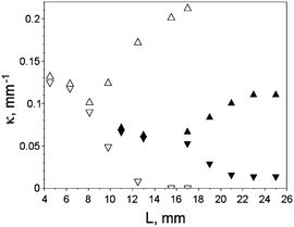
As pointed above, the films with embedded intrinsic in-plane strain, and having comparable width and length, undergo curvature bifurcation, as the dimension of the film or bending moment increase.18,24–29 This phenomenon distinguishes plates from beams, which are characterized by a unique curvature. Fig. 7 shows the maximum and the minimum curvatures, measured at the centers of the curved squares (Fig. S7, ESI†), for two square plates, with total thicknesses H1 = 0.8 mm and H2 = 1.3 mm.Increasing the film thickness predictably shifts the bifurcation point to higher values of the square side length, L. The dependence of the position of the bifurcation point on the geometrical and mechanical parameters of the bilayer square plates was investigated theoretically by Salamon and Masters25 in the limit of h2 ≪ h1, that is, the second layer being much thinner than the first one, which can be considered then as the substrate. For this case, their theory predicts the relation κB = AHL−2, where κB, H ≈ h1, and L denotes the curvature at the bifurcation point, film thickness and square side length, respectively, and A is a parameter depending on the mechanical constants of the layers (shear moduli and Poisson ratios) and the ratio of the layer thicknesses. When A is constant, as in the case of our experiment, then it should hold for any two bifurcation points (κB1H2L12)/(κB2H1L22) = 1. But, substitution of the experimental data from Table 3 in the last expression gives 0.47, which is twofold different than the theoretical value. In fact, this is not surprising, if we take into account, that the Timoshenko beam theory for the beams consisting of the layers of equal thicknesses predicts curvature scaling behaviour κ ∼H−1, while the Salamon–Masters theory considers the limit, for which the beam curvature is characterized by the Stoney formula36 and the curvature scales as κ ∼H−2.
| H, mm | 0.8 | 1.3 |
| L B, mm | 7.5 | 17 |
| κ B, mm−1 | 0.09 | 0.06 |
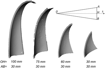
In past studies,18,24–29 thin plates were assumed to be rectangular or circular, and it was supposed that the two principal curvatures, κ1 and κ2, characterize the bifurcation behavior of the entire plate. PDMS films with intrinsic in-plane stress, introduced in the present paper, allow us to investigate experimentally the bifurcation effects of the plates of a multitude of shapes. In particular, we have found that one and the same plate can contain regions of spherical and cylindrical deformation modes, passing by the elliptical one. In other words, a curvature bifurcation transition can happen only on a part of a plate. To illustrate this point, we have prepared from the 1.3 mm-thick bilayer film (characterized by the equal thickness of the layers, and the initial oil content in the top film x = 0.2) a set of isosceles triangles with constant base AB = 30 mm and height OH varying from 100 to 30 mm (Fig. 8, inset). After the extraction of oil, the 3D-representations of the triangles were obtained using a David 3D scanner (Fig. 8). One can note immediately that the narrow part of the triangles is bent out of the plane formed by the triangle base and the triangle long axis. The scans were treated numerically by the Meshlab free software for curvature characterization. The boundary points of the scans were removed, and the noise was reduced by applying an embedded mean least square surface algorithm.37 Then the triangulated scans were colored according to the basic curvature characteristics. Coloring of the triangle with the largest aspect ratio OH/AB by the values of the principal curvatures κ1, κ2, the Gaussian curvature κ1κ2, and the mean curvature (κ1 + κ2)/2 is shown in Fig. S8 (ESI†). The bimodal distribution of the maximal curvature, κ1, corresponds to the concentration of the highest values of the characteristics in the vicinity of the base of the triangle. This is also the region of concentration of the smallest values of the minimal curvature, κ2. The Gaussian curvature correlates tightly with the minimal curvature, while the mean curvature is distributed more or less evenly over the figure.
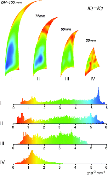
The most informative value for characterization of the bifurcation behaviour is the difference of the maximal and the minimal curvatures, Δκ = κ1 − κ2. Color mapping of the samples with different aspect ratios is shown in Fig. 9, together with the values of histograms. For the two triangles (I and II) with the highest aspect ratio, the curvature difference distribution has a distinctly bimodal character. The largest curvature difference is found in the broad part of the triangle, while the smallest difference is observed at the vertex angle of the triangles. As the aspect ratio diminishes, the distribution shifts to the region of smaller values. For the smallest triangle (IV), which is equilateral, it is distributed quasi-randomly over the sample. The distribution of the curvature difference over the triangles of the largest aspect ratios allows us to suppose that the thinnest part at the vertex angle can be characterized as experiencing spherical deformation (or close to such), while the broad part of the triangle, which is close to the triangle base, undergoes cylindrical deformation. One can assume then the existence of the curvature bifurcation point somewhere on the axis of the triangle. This suggestion is confirmed by figure Fig. 10, which plots the correlation of the principal curvatures at the vertices of the triangulated surfaces and the coordinates S of the vertices along the triangle's large axis (see Fig. 8, inset). The bifurcation seems to take place at 1/4 of the triangle height for the given sample.
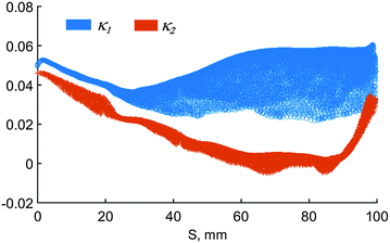 | ||
| Fig. 10 Correlation of the values of the principal curvatures with the coordinate S along the triangle long axis, for the triangle with the largest aspect ratio. | ||
3. Conclusion
We have proposed an approach for the design of thin elastic films with embedded mechanical stress, which results in a spontaneous curvature of the films. The fabrication procedure is remarkably straightforward and consists of forming a PDMS crosslinked bilayer in which the top layer contains silicone oil as the filler. The strain in the bifilm is generated upon oil extraction in a suitable organic solvent, leading to the collapse of the top layer onto itself. The lateral shrinking of the top layer is opposed by the bottom layer, whose dimensions are almost unchanged by the extraction procedure. The degree of stress can be easily controlled by the initial oil content in the top layer of the bifilm. Elastic bilayers with spontaneous curvature represent a convenient material for experimental studies in the behaviour of thin films with nonhomogeneous embedded stress. In particular, they are promising for the investigation of nonlinear geometrical effects of the curvature bifurcation of the films. An interesting problem that could be addressed by use of our films is the dependence of curvature bifurcation behaviour on the shape and size of film patterns. Thus, we have found that triangular plates are characterized by a nonuniform distribution of curvature characteristics, and the coexistence of spherical and cylinder deformation modes. The PDMS films with embedded stress could also have interesting applications, such as the macroscopic modelling of 3D shapes by self-folding of properly shaped 2D patterns that are cut from the films. PDMS microtubes, which are formed by self-rolling of the elastomer thin films with the embedded strain, may find numerous applications in microfluidics and adjacent fields. In the future studies, it will be interesting to combine our technique of the strain generation via a filler extrusion with the surface infusion micropatterning method,38 which consists in infiltration of photopolymerizable monomers in the elastomer matrix, followed by UV-light induced interpenetrating network formation. Complex patterns, which can be created within this approach with the use of photomasks, could enable further possibilities for the curvature and stress engineering of the elastomer films.4. Experimental
The lower 0.5 mm thick layer of PDMS (Sylgard 184) was prepared by pouring a mixture of polymer and curing agent in a volume ratio of 10![[thin space (1/6-em)]](https://www.rsc.org/images/entities/char_2009.gif) :
:![[thin space (1/6-em)]](https://www.rsc.org/images/entities/char_2009.gif) 1 into an aluminum receptacle. The layer was cured at 100 °C for 5 minutes. The second layer of the same thickness was formed from the mixture of PDMS, silicone oil (Rhodorsil, 47 V 350), and the curing agent. The mixture was poured on the top of the first layer and the second layer was cured using the same conditions as the first. The second layer can be created also locally on the top of the first layer, as in the case of discrete bending, shown in Fig. 4a. The beams with the alternating sign of bending were formed by the creation of the second layer on a half of the first layer, turning the system by 180° over the horizontal direction, and the creation of the second layer on the second half of the sample. The second layer should be formed immediately after the formation of the first layer, in order to avoid contamination of the interface between the layers, which could lead to reduced adhesion between the films. Oil was extracted in a chloroform bath for 48 hours at room temperature. Young moduli of PDMS with different initial oil fraction were estimated using the DMA method (Mettler DMA 861) at 0 Hz and were found to be 1.2 ± 0.1 MPa for x = 0, and 0.8 ± 0.1 MPa for x = 0.2, using macroscopic elastomer samples. The Poisson ratios for all the film compositions are supposed to be equal to ν = 0.5. For microtube fabrication, glass slides were first covered by spin-coating (500 rpm, 30 s) with coldwater fish gelatine wt% 1 solution (Sigma Aldrich G7041-100G). Then, ∼17 μm thick bilayers of PDMS with approximately equal thickness of each layer were formed by spin-coating (3000 rpm, 60 s) and crosslinking of the PDMS layer, followed by spin-coating (2000 rpm, 60 s) of the PDMS + silicon oil layer (50% volume fraction of oil with respect to PDMS). Both PDMS and PDMS + silicon oil were thinned by adding toluene in the 1
1 into an aluminum receptacle. The layer was cured at 100 °C for 5 minutes. The second layer of the same thickness was formed from the mixture of PDMS, silicone oil (Rhodorsil, 47 V 350), and the curing agent. The mixture was poured on the top of the first layer and the second layer was cured using the same conditions as the first. The second layer can be created also locally on the top of the first layer, as in the case of discrete bending, shown in Fig. 4a. The beams with the alternating sign of bending were formed by the creation of the second layer on a half of the first layer, turning the system by 180° over the horizontal direction, and the creation of the second layer on the second half of the sample. The second layer should be formed immediately after the formation of the first layer, in order to avoid contamination of the interface between the layers, which could lead to reduced adhesion between the films. Oil was extracted in a chloroform bath for 48 hours at room temperature. Young moduli of PDMS with different initial oil fraction were estimated using the DMA method (Mettler DMA 861) at 0 Hz and were found to be 1.2 ± 0.1 MPa for x = 0, and 0.8 ± 0.1 MPa for x = 0.2, using macroscopic elastomer samples. The Poisson ratios for all the film compositions are supposed to be equal to ν = 0.5. For microtube fabrication, glass slides were first covered by spin-coating (500 rpm, 30 s) with coldwater fish gelatine wt% 1 solution (Sigma Aldrich G7041-100G). Then, ∼17 μm thick bilayers of PDMS with approximately equal thickness of each layer were formed by spin-coating (3000 rpm, 60 s) and crosslinking of the PDMS layer, followed by spin-coating (2000 rpm, 60 s) of the PDMS + silicon oil layer (50% volume fraction of oil with respect to PDMS). Both PDMS and PDMS + silicon oil were thinned by adding toluene in the 1![[thin space (1/6-em)]](https://www.rsc.org/images/entities/char_2009.gif) :
:![[thin space (1/6-em)]](https://www.rsc.org/images/entities/char_2009.gif) 1 proportion. Extraction was done in a 2-propanol (VWR Chemicals) bath for 4 hours. 3D scans of the curved films were obtained with the use of a DAVID SLS-2 scanner. In order to enable scanning of the transparent PDMS films, the DAVID coating spray was applied to the films. Curvature mapping of the scans was performed by the MeshLab software. Prior to curvature measurements and scanning, the triangles and other figures were mounted on a needle (as shown in Fig. S7 (ESI†), but in most cases the needle did not transpierce the sample) and held so that the figure is deflected from a vertical plane. In this case, gravity creates minimal bending moments in the films, and the adhesion to a substrate is avoided. The curvature of the beams was not affected by the gravity, because their deflection plane is parallel to the horizontal substrate (Fig. S3 and S5, ESI†).
1 proportion. Extraction was done in a 2-propanol (VWR Chemicals) bath for 4 hours. 3D scans of the curved films were obtained with the use of a DAVID SLS-2 scanner. In order to enable scanning of the transparent PDMS films, the DAVID coating spray was applied to the films. Curvature mapping of the scans was performed by the MeshLab software. Prior to curvature measurements and scanning, the triangles and other figures were mounted on a needle (as shown in Fig. S7 (ESI†), but in most cases the needle did not transpierce the sample) and held so that the figure is deflected from a vertical plane. In this case, gravity creates minimal bending moments in the films, and the adhesion to a substrate is avoided. The curvature of the beams was not affected by the gravity, because their deflection plane is parallel to the horizontal substrate (Fig. S3 and S5, ESI†).
Acknowledgements
The authors gratefully acknowledge financial support by the French National Research Agency, award no. ANR-13-IS09-0002-01. JGK acknowledges additional support from the ERC grant 290586 NMCEL. Gauthier Schrodl is acknowledged for the DMA measurements.Notes and references
- Selections from a collection of dried Western sycamore leaves (Platanus racemosa), http://pamelaburgess.com/western-sycamore/.
- H. Xiao and X. Chen, Soft Matter, 2011, 7, 10794 RSC.
- A. V. Prinz, V. Ya. Prinz and V. A. Seleznev, Microelectron. Eng., 2003, 67–68, 782 CrossRef CAS.
- T. Kipp, H. Welsch, Ch. Strelow, Ch. Heyn and D. Heitmann, Phys. Rev. Lett., 2006, 96, 077403 CrossRef CAS PubMed.
- Ch. Deneke, N.-Y. Jin-Phillipp, I. Loa and O. G. Schmidt, Appl. Phys. Lett., 2004, 84, 4475 CrossRef CAS.
- M. Yu, Y. Huang, J. Ballweg, H. Shin, M. Huang, D. E. Savage, M. G. Lagally, E. W. Dent, R. H. Blick and J. C. Williams, ACS Nano, 2011, 5, 2447 CrossRef CAS PubMed.
- E. J. Smith, W. Xi, D. Makarov, I. Mönch, S. Harazim, V. A. Bolaños Quiñones, C. K. Schmidt, Y. Mei, S. Sanchez and O. G. Schmidt, Lab Chip, 2012, 12, 1917 RSC.
- J. S. Randhawa, M. D. Keung, P. Tyagi and D. H. Gracias, Adv. Mater., 2010, 22, 407–410 CrossRef CAS PubMed.
- V. A. Luchnikov, O. Sydorenko and M. Stamm, Adv. Mater., 2005, 17, 1177 CrossRef CAS.
- S. Zakharchenko, N. Puretskiy, G. Stoychev, M. Stamm and L. Ionov, Soft Matter, 2010, 6, 2633 RSC.
- S. Zakharchenko, E. Sperling and L. Ionov, Biomacromolecules, 2011, 12, 2211 CrossRef CAS PubMed.
- L. P. C. Gómez, P. Bollgruen, A. I. Egunov, D. Mager, F. Malloggi, J. G. Korvink and V. A. Luchnikov, Lab Chip, 2013, 13, 3827 RSC.
- G. Stoychev, N. Pyretskiy and L. Ionov, Soft Matter, 2011, 7, 3277 RSC.
- V. A. Luchnikov, L. Ionov and M. Stamm, Macromol. Rapid Commun., 2011, 32, 1943 CrossRef CAS PubMed.
- V. A. Luchnikov, Y. Saito and L. Tzanis, Macromol. Rapid Commun., 2012, 33, 1404 CrossRef CAS PubMed.
- S. Douezan, M. Wyart, F. Brochard-Wyart and D. Cuvelier, Soft Matter, 2011, 7, 1506 RSC.
- E. Reyssat and L. Mahadevan, Europhys. Lett., 2011, 93, 54001 CrossRef.
- D. P. Holmes, M. Roché, T. Sinha and H. A. Stone, Soft Matter, 2011, 7, 5188 RSC.
- A. Agrawal, T. H. Yun, S. L. Pesek, W. G. Chapman and R. Verduzco, Soft Matter, 2014, 10, 1411–1415 RSC.
- X. Mu, N. Sowan, J. A. Tumbic, C. N. Bowman, P. T. Mther and H. Jerry Qi, Soft Matter, 2015, 11, 2673 RSC.
- S. Taccola, F. Greco, E. Sinibaldi, A. Mondini, B. Mazzolai and V. Mattoli, Adv. Mater., 2015, 27, 1668–1675 CrossRef CAS PubMed.
- E. W. H. Jager, E. Smela and O. Inganäs, Science, 2000, 290, 1540–1545 CrossRef CAS PubMed.
- J. Huang, J. Liu, B. Kroll, K. Bertoldi and D. R. Clarke, Soft Matter, 2012, 8, 6291 RSC.
- C. B. Masters and N. J. Salamon, J. Appl. Mech., 1994, 61, 872 CrossRef.
- N. J. Salamon and C. B. Masters, Int. J. Solids Struct., 1995, 3/4, 473 CrossRef.
- V. M. Morton, Corros. Sci., 1969, 9, 261 CrossRef.
- L. B. Freund, J. Mech. Phys. Solids, 2000, 48, 1159 CrossRef CAS.
- B. D. Harper and C.-P. Wu, Int. J. Solids Struct., 1990, 5/6, 511 CrossRef.
- M. L. Dunn, Y. Zhang and V. M. Bright, J. Microelectromech. Syst., 2002, 11, 372 CrossRef.
- S. Timoshenko, J. Opt. Soc. Am., 1925, 11, 233 CrossRef CAS.
- This term seems to us to be more appropriate to the approach, than the name origami, used sometimes in the field.
- Y. Klein, E. Efrati and E. Sharon, Shaping of elastic sheets by prescription of non-euclidean metrics, Science, 2007, 315, 1116 CrossRef CAS PubMed.
- W. Z. Liang, M. Moshe, J. Greener, H. Therien-Aubin, Z. Nie, E. Sharon and E. Kumacheva, Nat. Commun., 2013, 4, 1586 CrossRef PubMed.
- M. Pezzulla, S. A. Shillig, P. Nardinocchi and D. P. Holmes, Soft Matter, 2015, 11, 5812–5820 RSC.
- J. N. Lee, C. Park and G. M. Whitesides, Anal. Chem., 2003, 75, 6544–6554 CrossRef CAS PubMed.
- G. G. Stoney, Proc. R. Soc. London, Ser. A, 1909, 82, 172 CrossRef CAS.
- G. Guennenbaud and M. Gross, Algebraic Point Set Surfaces, Siggraph, 2007 Search PubMed.
- H. Chen, D. M. Lentz, A. M. Rhoades, R. A. Pyles, K. W. Haider, S. A. Vanapalli, R. K. Nunley and R. C. Hedden, Microfluid. Nanofluid., 2012, 12, 451 CrossRef CAS.
Footnote |
| † Electronic supplementary information (ESI) available: Fig. S1–S5, and the accompanying text. See DOI: 10.1039/c5sm01139f |
| This journal is © The Royal Society of Chemistry 2016 |

