 Open Access Article
Creative Commons Attribution 3.0 Unported Licence
Dithieno[3,2-b:2′,3′-d]pyridin-5(4H)-one based D–A type copolymers with wide bandgaps of up to 2.05 eV to achieve solar cell efficiencies of up to 7.33%†
Wei
Gao‡
a,
Tao
Liu‡
b,
Minghui
Hao
a,
Kailong
Wu
a,
Chen
Zhang
a,
Yanming
Sun
*b and
Chuluo
Yang
*a
aHubei Collaborative Innovation Center for Advanced Organic Chemical Materials, Hubei Key Lab on Organic and Polymeric Optoelectronic Materials, Department of Chemistry, Wuhan University, Wuhan 40072, China. E-mail: clyang@whu.edu.cn
bHeeger Beijing Research and Development Center, School of Chemistry and Environment, Beihang University, Beijing 100191, P. R. China. E-mail: sunym@buaa.edu.cn
First published on 10th June 2016
Abstract
Two new polymers, PDTPO-IDT and PDTPO-IDTT, are synthesized through copolymerization of 4-(2-octyldodecyl)-dithieno[3,2-b:2′,3′-d]pyridin-5(4H)-one (DTPO) with indacenodithiophene (IDT) or indacenodithieno[3,2-b]thiophene (IDTT). The rational combination of the planar DTPO unit with ladder-type IDT and IDTT units endows the resulting copolymers with wide optical bandgaps of ca. 2.05 eV, low HOMO energy levels of ca. −5.32 eV and good hole-transporting abilities with a hole mobility of 1.0 × 10⁻³ cm2 V−1 s−1. The polymer solar cell (PSC) in a conventional structure based on PDTPO-IDT as donor and [6,6]-phenyl-C71-butyric acid methyl ester (PC71BM) as acceptor achieves a high power conversion efficiency (PCE) of up to 7.33%, the highest value for PSCs based on polymers with optical bandgap over 2.0 eV to date, along with a remarkable open-circuit voltage (Voc) approaching 0.97 V. The performance of the PDTPO-IDTT based PSC is slightly behind this with a moderate PCE of 5.47% under the same conditions. The relationship between the copolymer structures and optoelectronic properties as well as photovoltaic performance are comprehensively investigated by experiments and theoretical simulations.
Introduction
Organic photovoltaics (OPVs), emerging as an environmentally benign technology with the function of converting solar energy into electricity, have shown attractive prospects owing to their low-cost, low weight, large area and flexible fabrication.1–8 Gratifyingly, through in-depth research on theories9–11 and novel materials,5,12–16 the power conversion efficiency (PCE) of bulk heterojunction (BHJ) solar cells based on conjugated polymers as donors and [6,6]-phenyl-C71/C61-butyric acid methyl ester (PC71BM or PC61BM) as acceptors have reached over 10% for single junction solar cells17–22 and 11% for tandem solar cells.23,24 Such high efficiency polymer solar cells (PSCs) usually employ photoactive materials with low or medium bandgaps, for the purpose of enlarging incident light harvesting and originally promoting short circuit current density (Jsc). Compared to low and medium bandgap materials, wide bandgap materials have lagged behind, and only a few of them have achieved efficiencies of over 7%,25,26 in particular when the bandgap exceeds 2.0 eV. This is because such kinds of polymers suffer from an inherent defect of a narrow absorption band below 650 nm (optical bandgap [Eg] > 1.9 eV) in the solar spectrum, which is not conducive to the full use of a high luminous flux section of the solar spectrum and directly limits the photocurrent at the first step of exciton generation. However, Jsc is only one of the key factors determining the efficiency of BHJ solar cells. That means we are able to optimize the other two key factors: open circuit voltage (Voc) and fill factor (FF) through reasonable material design and careful device processing. Moreover, from a material engineering perspective, Jsc can be fine-tuned by effective exciton separation and enhancement of charge-carrier mobility through morphological control, device structure optimization as well as interlayer engineering. In addition, wide bandgap materials are critical to construct high performance tandem solar cells in which they can act as a photoactive layer in the front cell of a tandem solar cell combined with a rear cell using low bandgap materials to implement the full absorption of the solar spectrum.27,28Ladder-type electron-donor units with linearly fused aromatic or heteroaromatic subunits have been widely utilized to build low and medium bandgap materials.29–32 This is because covalently forced planarization can extend effective conjugation length along a polymer backbone and promote π-electron delocalization between parallel p-orbitals. Moreover, a structure with rigid coplanarity may restrain rotational disorder to lower reorganization energy, which benefits the charge carrier mobility. Indacenodithiophene (IDT) and indacenodithieno[3,2-b]thiophene (IDTT) are popular ladder-type building blocks with five-membered and seven-membered multifused rings, respectively. When they are copolymerized with common electron-deficient units, such as 4,7-dibromo-2,1,3-benzothiadiazole (BT),31,33–35 4,7-dibromo-5,6-difluoro-2,1,3-benzothiadiazole (2FBT),34–36 1,3-dibromo-thieno[3,4-c]pyrrol-4,6-dione (TPD),35,37–39 the absorption spectra of the resulting polymers often exhibit, to a certain extent, blue shifting compared with polymers based on 4,8-bis(2-ethylhexyloxy)benzo[1,2-b:4,5-b′]dithiophene (BDTO) and 4,8-bis(5-(2-ethylhexyl)thiophen-2-yl)benzo[1,2-b:4,5-b′]dithiophene (BDTT) coupled with similar acceptor units. This means that both IDT and IDTT are weaker electron donors than benzodithiophenes (BDTO and BDTT), which will facilitate wide bandgap.
Recently, Yu’s group and our group reported a novel structure of two thiophenes flanking a tricyclic pyridone, 4-(2-octyldodecyl)-dithieno[3,2-b:2′,3′-d]pyridin-5(4H)-one (DTPO).40,41 The copolymers based on DTPO and BDTs (PDTPO-BDTO and PDTPO-BDTT) showed bandgaps of around 2.0 eV and a relatively low HOMO energy level of −5.44 eV which led to a high Voc of 0.98 V, and PCEs of up to 6.84% were achieved in PSCs. Meanwhile, the homopolymer of DTPO revealed a high hole mobility in an organic field-effect transistor (OFET). These results indicated that DTPO is a good building block for wide bandgap materials.
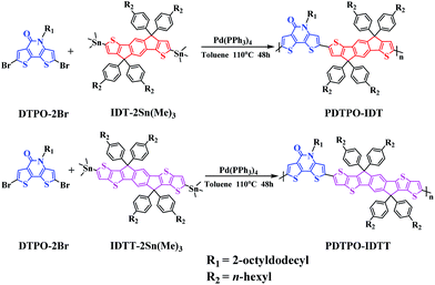
Aiming to explore new wide bandgap materials, herein, we designed and synthesized two new polymers, PDTPO-IDT and PDTPO-IDTT (Scheme 1), by replacing BDTs with IDT and IDTT units as electron donors to copolymerize with the DTPO unit. We anticipate that the combination of ladder-type IDT and IDTT units with the DTPO unit would facilitate the planarization of the copolymers, strengthen intermolecular π–π stacking and improve their charge-carrier transporting properties. The two copolymers show wide bandgaps of ca. 2.05 eV. Noticeably, PSCs based on PDTPO-IDT exhibited high Voc of up to 0.98 V and achieved PCEs of up to 7.33%.
Results and discussion
Synthesis and characterization
As shown in Scheme 1, the copolymers of PDTPO-IDT and PDTPO-IDTT were prepared by the Stille polycondensation between the monomer of DTPO-2Br and commercially available monomers of IDT-2Sn(Me)3 and IDTT-2Sn(Me)3. The structures of the two polymers were characterized by 1H NMR and elemental analysis (EA). The number-average molecular weights (Mn) and polydispersity indices (PDI) of PDTPO-IDT and PDTPO-IDTT are 23.9 kDa/1.75 and 30.2 kDa/2.28, respectively, measured by gel permeation chromatography (GPC) with polystyrene as the standard. The two polymers showed good solubility in common solvents, such as chloroform (CF), tetrahydrofuran (THF), chlorobenzene (CB) and o-dichlorobenzene (o-DCB).As shown in Fig. S1,† the decomposition temperatures (Td) with 5% weight loss are 440 °C for PDTPO-IDT and 436 °C for PDTPO-IDTT, indicating that the two polymers are stable enough for application in PSC devices.
Optical properties
The UV-vis absorption spectra of PDTPO-IDT and PDTPO-IDTT in chloroform solution, pure films and blend films are shown in Fig. 1, and the corresponding absorption maxima and molar extinction coefficients are listed in Table 1. As shown, both the spectra profiles and absorption peaks of the two polymers are similar in chloroform solution and pure films, attributed to the similar structures between IDT and IDTT. Unlike the absorption spectra of other conjugated polymers with extended fused ring systems, the absorption peak resulting from localized π–π* transitions at short wavelengths is absent in both solution and pure films, which is similar to those polymers with optical bandgap over 2.0 eV.25,43–45 The broad absorption bands ranging from 400 to 600 nm are ascribed to intramolecular charge transfer (ICT). In addition, strong vibronic shoulder peaks are observed in both solution and pure films of the two polymers, demonstrating the existence of strong π–π stacking between polymer chains. The two polymers exhibit high molar extinction coefficients of 8.33 × 10⁴ M−1 cm−1 for PDTPO-IDT and 1.32 × 10⁵ M−1 cm−1 for PDTPO-IDTT in chloroform solution. In order to understand the absorption behavior of the active layers, the blend films of the polymers and PC71BM were investigated. The complementary absorption spectra of PC71BM and PDTPO-IDT contribute to a 24 nm expansion of the absorption band of PDTPO-IDT. In contrast, the spectra of PC71BM and PDTPO-IDTT blend films have a negligible effect on the absorption band at long wavelength. The optical bandgaps calculated from the absorption edge of pure films spectra are 2.05 eV for PDTPO-IDT and 2.04 eV for PDTPO-IDTT, respectively.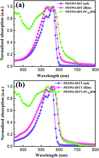 | ||
| Fig. 1 Normalized UV-vis absorption spectra in chloroform solution, pure films and blend films for PDTPO-IDT (a) and PDTPO-IDTT (b). | ||
| Polymer | M n (kDa) | PDI | T d (°C) | ε max (M−1 cm−1) | λ max (nm) | λ max (nm) | λ onset (nm) | E optg (eV) | HOMO (eV) | LUMOf (eV) |
|---|---|---|---|---|---|---|---|---|---|---|
| a Measured by GPC with polystyrene as the standard. b Obtained from TGA with 5% weight loss. c In chloroform solution. d In pure film drop-cast from chloroform solution. e Calculated from Eoptg = 1240/λonset. f Obtained from ELUMO = Eoptg + EHOMO. | ||||||||||
| PDTPO-IDT | 23.9 | 1.7 | 440 | 8.33 × 10⁴ | 528 | 531 | 604 | 2.05 | −5.32 | −3.27 |
| 563 | 566 | |||||||||
| PDTPO-IDTT | 30.2 | 2.2 | 436 | 1.32 × 10⁵ | 524 | 532 | 607 | 2.04 | −5.31 | −3.27 |
| 557 | 569 | |||||||||
Electrochemical properties
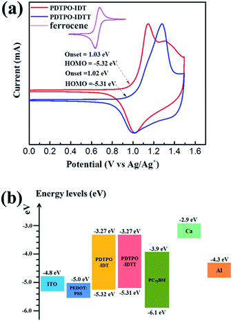
Cyclic voltammetry (CV) was carried out to estimate the highest occupied molecular orbital (HOMO) and lowest unoccupied molecular orbital (LUMO) energy levels of the two polymers. As displayed in Fig. 2a, both polymers show reversible oxidation processes. The oxidation onset potentials (Eox) of PDTPO-IDT and PDTPO-IDTT referenced to Ag/AgCl (Ag/Ag+) were found to be 1.03 V and 1.02 V, respectively, corresponding to HOMO energy levels of −5.32 eV and −5.31 eV. The LUMO energy levels were calculated from the equation: ELUMO = (EHOMO + Eoptg) eV. Both copolymers have the same LUMOs of −3.27 eV, which are higher than those of PDTPO-BDTO (−3.37 eV) and PDTPO-BDTT (−3.35 eV) which we previously reported.40 This means that the offsets between the LUMO energy levels of donor and acceptor (PC71BM) tend to become larger, which will provide a greater driving force to accelerate the exciton separation, and decrease the exciton recombination rate around the interface between donor and acceptor.Theoretical calculations
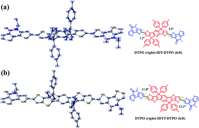
To further understand the effect of copolymer planarization, theoretical calculations were performed by using density functional theory (DFT) at the B3LYP/6-31G* level. Taking the asymmetrical characteristic of DTPO units into consideration, one and a half repeating units were employed as a simplified model to simulate the whole molecular skeleton. The long alkyl side chains were replaced with methyl groups to further simplify the calculation. As illustrated in Fig. 3, DTPO and IDT/IDTT units were found to be oriented in antiparallel equilibrium geometries. Due to the different chemical environments of C79 (C114) and C105 (C85) in the DTPO unit observed from the 13C NMR of DTPO (Fig. S5†), there is a 2.7° difference between the dihedral angle φ(C80–C79–C15–S19) (1.2°) and φ(C4–C1–C105–S107) (3.9°). A similar situation occurs for DTPO-IDTT-DTPO with the difference between the dihedral angles φ(C112–C111–C4–S11) (11.8°) and φ(C13–C16–C85–S87) (13.2°) being 1.4°. A larger torsion angle in PDTPO-IDTT results from larger steric hindrance of IDTT due to the interactions between ipsilateral alkyl chains of the donor and acceptor. The larger dihedral angles of PDTPO-IDTT over PDTPO-IDT suggest a larger change of the planarity from solution to solid state,42 which is consistent with a larger red shift of absorption spectra of PDTPO-IDTT from solution to solid state.The HOMO and LUMO orbitals of the model compounds are shown in Fig. S2.† Both HOMO and LUMO frontier orbitals of PDTPO-IDT and PDTPO-IDTT are well-proportionally distributed along the whole conjugated plane, which would be favorable to the charge carrier transport. Unlike low bandgap polymers, such an orbital distribution reveals a weak intramolecular charge transfer, which explains the reason why the maximum absorption values of the two polymers are below 600 nm.
Photovoltaic performance
The photovoltaic properties of PDTPO-IDT and PDTPO-IDTT were evaluated in a conventional device structure: ITO/PEDOT:PSS (40 nm)/polymer:PC71BM (85 nm)/Ca (20 nm)/Al (100 nm) (Fig. S3†), where ITO (indium tin oxide) was the anode, PEDOT:PSS (poly(3,4-ethylenedioxythiophene):poly(styrenesulfonate)) was used as the hole transporting layer (HTL), PC71BM served as the electron acceptor, and Ca/Al worked together as the cathode. The active layers were fabricated by spin-coating a blend solution of PDTPO-IDT (or PDTPO-IDTT) and PC71BM in o-DCB (10 mg mL−1) with an optimal weight ratio of 1![[thin space (1/6-em)]](https://www.rsc.org/images/entities/char_2009.gif) :
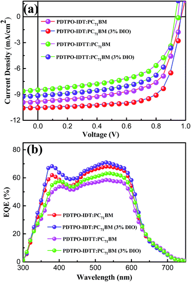
:![[thin space (1/6-em)]](https://www.rsc.org/images/entities/char_2009.gif) 2 at 1600 rounds per minute (rpm), controlling the film thickness at ca. 85 nm. 3% (v/v) 1,8-diiodoctane (DIO) was employed as a solution additive to optimize the nanoscale morphology. Characteristic current density–voltage (J–V) curves of the studied PSCs as well as corresponding external quantum efficiency (EQE) spectra are shown in Fig. 4. The key photovoltaic parameters are summarized in Table 2. PSCs based on PDTPO-IDT
2 at 1600 rounds per minute (rpm), controlling the film thickness at ca. 85 nm. 3% (v/v) 1,8-diiodoctane (DIO) was employed as a solution additive to optimize the nanoscale morphology. Characteristic current density–voltage (J–V) curves of the studied PSCs as well as corresponding external quantum efficiency (EQE) spectra are shown in Fig. 4. The key photovoltaic parameters are summarized in Table 2. PSCs based on PDTPO-IDT![[thin space (1/6-em)]](https://www.rsc.org/images/entities/char_2009.gif) :
:![[thin space (1/6-em)]](https://www.rsc.org/images/entities/char_2009.gif) PC71BM (1
PC71BM (1![[thin space (1/6-em)]](https://www.rsc.org/images/entities/char_2009.gif) :
:![[thin space (1/6-em)]](https://www.rsc.org/images/entities/char_2009.gif) 2, w/w) and PDTPO-IDTT
2, w/w) and PDTPO-IDTT![[thin space (1/6-em)]](https://www.rsc.org/images/entities/char_2009.gif) :
:![[thin space (1/6-em)]](https://www.rsc.org/images/entities/char_2009.gif) PC71BM (1
PC71BM (1![[thin space (1/6-em)]](https://www.rsc.org/images/entities/char_2009.gif) :
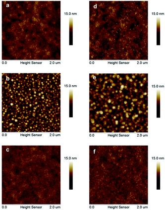
:![[thin space (1/6-em)]](https://www.rsc.org/images/entities/char_2009.gif) 2, w/w) showed high Voc values in the range of 0.94–0.98 V. After adding 3% DIO as additive, the Voc values of the two PSCs slightly declined by 0.01 V. However, the Jsc, FF and hole mobility values showed simultaneous enhancement for both PSCs, which is beneficial to achieve higher PCEs. When the donor unit copolymerized with DTPO is changed from IDTT to IDT, the Voc, Jsc, FF and PCE showed obvious improvement with/without a DIO additive. This can be elucidated from the following aspects: (i) the blend film of PDTPO-IDT and PC71BM exhibit a broader absorption band than PDTPO-IDTT, which is helpful to attain a larger Jsc; (ii) the blend film of PDTPO-IDT and PC71BM showed a more uniform morphology (Fig. 6c and f) and higher hole mobility than PDTPO-IDTT (Fig. 5), which will be discussed below. A solar cell efficiency of 7.33% was achieved in the PSC based on PDTPO-IDT accompanied with a high Voc of 0.97 V, high FF of 71.5% and a relatively large Jsc of 10.55 mA cm−2. To the best of our knowledge, this PCE value represents the highest value so far for PSCs based on polymers with bandgaps over 2.0 eV (see Table 3). Additionally, an average PCE of 7.17% for PDTPO-IDT was obtained from 20 devices, indicating good reproducibility.
2, w/w) showed high Voc values in the range of 0.94–0.98 V. After adding 3% DIO as additive, the Voc values of the two PSCs slightly declined by 0.01 V. However, the Jsc, FF and hole mobility values showed simultaneous enhancement for both PSCs, which is beneficial to achieve higher PCEs. When the donor unit copolymerized with DTPO is changed from IDTT to IDT, the Voc, Jsc, FF and PCE showed obvious improvement with/without a DIO additive. This can be elucidated from the following aspects: (i) the blend film of PDTPO-IDT and PC71BM exhibit a broader absorption band than PDTPO-IDTT, which is helpful to attain a larger Jsc; (ii) the blend film of PDTPO-IDT and PC71BM showed a more uniform morphology (Fig. 6c and f) and higher hole mobility than PDTPO-IDTT (Fig. 5), which will be discussed below. A solar cell efficiency of 7.33% was achieved in the PSC based on PDTPO-IDT accompanied with a high Voc of 0.97 V, high FF of 71.5% and a relatively large Jsc of 10.55 mA cm−2. To the best of our knowledge, this PCE value represents the highest value so far for PSCs based on polymers with bandgaps over 2.0 eV (see Table 3). Additionally, an average PCE of 7.17% for PDTPO-IDT was obtained from 20 devices, indicating good reproducibility.
![[thin space (1/6-em)]](https://www.rsc.org/images/entities/char_2009.gif) :
:![[thin space (1/6-em)]](https://www.rsc.org/images/entities/char_2009.gif) PC71BM (1
PC71BM (1![[thin space (1/6-em)]](https://www.rsc.org/images/entities/char_2009.gif) :
:![[thin space (1/6-em)]](https://www.rsc.org/images/entities/char_2009.gif) 2, w/w) and PDTPO-IDTT
2, w/w) and PDTPO-IDTT![[thin space (1/6-em)]](https://www.rsc.org/images/entities/char_2009.gif) :
:![[thin space (1/6-em)]](https://www.rsc.org/images/entities/char_2009.gif) PC71BM (1
PC71BM (1![[thin space (1/6-em)]](https://www.rsc.org/images/entities/char_2009.gif) :
:![[thin space (1/6-em)]](https://www.rsc.org/images/entities/char_2009.gif) 2, w/w) in conventional structures under AM 1.5 G at 100 mW cm−2
2, w/w) in conventional structures under AM 1.5 G at 100 mW cm−2
| Donor | Acceptor | E optg (eV) | PCE (%) | V oc (V) | J sc (mA cm−2) | FF | E HOMO (eV) | E LUMO (eV) | Ref. |
|---|---|---|---|---|---|---|---|---|---|
| a Obtained from cyclic voltammetry. b Achieved with an inverted architecture. c Obtained from ultraviolet photoelectron spectroscopy. | |||||||||
| PDTPO-IDT | PC71BM | 2.05 | 7.33 | 0.97 | 10.55 | 0.71 | −5.32 | −3.27 | This work |
| PDTPO-IDTT | PC71BM | 2.04 | 5.43 | 0.94 | 9.14 | 0.64 | −5.31 | −3.27 | This work |
| PDTPO-BDTO | PC71BM | 2.02 | 6.84 | 0.93 | 10.4 | 0.70 | −5.38 | −3.37 | 40 |
| PTADTBTO | PC71BM | 2.10 | 4.64 | 0.85 | 11.02 | 0.59 | −5.38 | −3.28 | 48 |
| PBDTT | PC71BM | 2.13 | 6.12 | 0.93 | 11.95 | 0.55 | −5.44 | −3.46 | 47 |
| PBDT[2F]T | PC71BM | 2.1 | 7.0 | 0.9 | 10.7 | 0.72 | −5.29 | NA | 26 |
| PIDTT-TzTz | PC71BM | 2.0 | 5.9 | 0.9 | 10.41 | 0.59 | −5.24 | −3.21 | 45 |
| BTT-BTz | PC71BM | 2.05 | 5.06 | 0.81 | 10.9 | 0.57 | −5.65c | −3.60 | 43 |
| HMW-P1 | PC71BM | 2.0 | 6.52 | 0.90 | 12.72 | 0.57 | −5.41 | −3.41 | 49 |
| PBnDT-FTAZ | PC61BM | 2.00 | 7.10 | 0.79 | 12.45 | 0.72 | −5.36 | −3.05 | 25 |
| PPDT1 | PC71BM | 2.00 | 3.28 | 0.87 | 8.30 | 0.45 | −5.27 | −2.68 | 41 |
The external quantum efficiency (EQE) curves of PDTPO-IDT![[thin space (1/6-em)]](https://www.rsc.org/images/entities/char_2009.gif) :
:![[thin space (1/6-em)]](https://www.rsc.org/images/entities/char_2009.gif) PC71BM and PDTPO-IDTT
PC71BM and PDTPO-IDTT![[thin space (1/6-em)]](https://www.rsc.org/images/entities/char_2009.gif) :
:![[thin space (1/6-em)]](https://www.rsc.org/images/entities/char_2009.gif) PC71BM based devices under optimized conditions are shown in Fig. 4b. Broad EQE spectra are observed in the range of 300 to700 nm, which is extended by dozens of nanometers relative to the UV-vis absorption range at long wavelengths. The PSC based on PDTPO-IDT
PC71BM based devices under optimized conditions are shown in Fig. 4b. Broad EQE spectra are observed in the range of 300 to700 nm, which is extended by dozens of nanometers relative to the UV-vis absorption range at long wavelengths. The PSC based on PDTPO-IDT![[thin space (1/6-em)]](https://www.rsc.org/images/entities/char_2009.gif) :
:![[thin space (1/6-em)]](https://www.rsc.org/images/entities/char_2009.gif) PC71BM (1
PC71BM (1![[thin space (1/6-em)]](https://www.rsc.org/images/entities/char_2009.gif) :
:![[thin space (1/6-em)]](https://www.rsc.org/images/entities/char_2009.gif) 2, w/w) exhibited an EQE exceeding 60% in range of 370 to 590 nm with the maximum value over 70% at 530 nm. The measured Jsc of two PSCs were well matched with the corresponding integral value of the EQE spectra within an error of 4%.
2, w/w) exhibited an EQE exceeding 60% in range of 370 to 590 nm with the maximum value over 70% at 530 nm. The measured Jsc of two PSCs were well matched with the corresponding integral value of the EQE spectra within an error of 4%.
Hole mobility properties and morphology
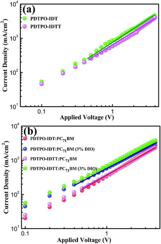
Hole mobility is an important factor for the performance of PSCs. The hole mobilities of PDTPO-IDT and PDTPO-IDTT in both pure films and blend films were investigated by employing hole-only devices with the following structure:ITO/MoO3/polymer/MoO3/Al for the pure films and ITO/MoO3/polymer:PC71BM/MoO3/Al for the blend films using the space-charge-limited current (SCLC) method. Current–voltage (I–V) characteristics and SCLC fittings of devices are shown in Fig. 5. In the pure films, PDTPO-IDT and PDTPO-IDTT exhibit the same hole mobilities of 1.0 × 10⁻³ cm2 V−1 s−1. In the blend films without DIO, the hole mobilities of PDTPO-IDT and PDTPO-IDTT are 7.6 × 10⁻⁴ cm2 V−1 s−1 and 6.0 × 10⁻⁴ cm2 V−1 s−1, respectively. When 3% DIO was added, the hole mobilities are increased to 8.7 × 10⁻⁴ cm2 V−1 s−1 and 7.6 × 10⁻⁴ cm2 V−1 s−1, respectively. Compared with the pure films, the presence of PC71BM in blend films had a negative effect on the molecular packing and the hole mobility. But the difference of hole mobilities between pure film and blend film are not obvious, indicating that the two polymers have good miscibility with PC71BM under the aid of solution annealing by molecular reorganization and repacking, which will contribute to the formation of good phase separation and favorable morphologies. This can also be evident from the atomic force microscopy (AFM) images shown in Fig. 6. The pure films of PDTPO-IDT and PDTPO-IDTT displayed smooth and uniform morphology with root-mean-square (RMS) surface roughness of 0.875 nm and 0.986 nm, respectively. When PC71BM was blended without the 3% DIO additive, it is clearly observed from AFM images (Fig. 6b and e) that many small particles aggregated to form severe phase separations, which is not conducive to charge carrier transport. When 3% DIO was added, the small particles disappeared and the surface morphology returned to a more smooth and uniform state with a RMS roughness of 0.679 nm and 0.719 nm, respectively, indicating that DIO addition played an important role in morphology control.
PDTPO-IDT and PDTPO-IDTT possess lower HOMO energy levels than P3HT (−5.19 eV) by about 0.23 eV. Hence, higher Voc values in PDTPO-IDT and PDTPO-IDTT based PSCs could be anticipated compared to that of the P3HT based PSC, as the Voc value and the difference in energy between the HOMO of the electron donor and the LUMO of the electron acceptor are positively and linearly correlated.50,51 Interestingly, the HOMO energy level of PDTPO-IDT is higher than that of PDTPO-BDTO (−5.38 eV) by 0.06 eV,40 however, the PDTPO-IDT based PSC achieved a higher Voc (Table 3). This cannot be simply explained by using the above-mentioned principle. A more accurate Voc value can be calculated using the following equation:46
 | (1) |
Conclusion
In summary, we developed two new wide bandgap polymers through the combination of ladder-type IDT/IDTT units with the planar DTPO unit. Both of the two polymers showed wide optical bandgaps exceeding 2.0 eV and deep HOMO energy levels of ca. −5.32 eV. PSCs based on PDTPO-IDT with bandgaps of up to 2.05 eV achieved a remarkable Voc of 0.97 V and a high efficiency of 7.33%. PDTPO-IDTT based PSCs showed a moderate PCE of 5.47%. The small torsion angle, high hole mobility and uniform morphology contribute to the high performance of the PDTPO-IDT based PSCs. We believe that the wide optical bandgap and excellent device performance of PDTPO-IDT will make it a promising candidate for tandem and ternary organic solar cells.Experimental section
General information
All chemicals were purchased from commercial sources and used without further purification unless otherwise stated. The solvents were dried using standard procedures when necessary. 2,8-Bis(trimethyltin)-indacenodithiophene (IDT-2Sn(Me)3) and 2,10-bis(trimethyltin)-indacenodithieno[3,2-b]thiophene (IDTT-2Sn(Me)3) were purchased from commercial sources with a purity of 98%. Monomer 2,6-dibromo-4-(2-octyldodecyl)-dithieno[3,2-b:2′,3′-d]pyridin-5(4H)-one (DPTO-2Br) was synthesized according to literature methods.40 UV-vis spectra were measured using a Shimadzu UV-2500 recording spectrophotometer. 1H and 13C NMR spectra were collected on a MERCURY-VX300 spectrometer operating at 300 MHz using deuterated chloroform referenced to tetramethylsilane (TMS). Electron ionization mass spectrometry (EI-MS) was recorded on a VJ-ZAB-3F-mass spectrometer. Elemental analysis (EA) was carried out on a Vario EL-III microanalyzer to identify the content of carbon, hydrogen, nitrogen and sulfur. Gel permeation chromatography (GPC) was measured on a Waters 2690 D system using a refractive detector and tetrahydrofuran (THF) as the eluent. Cyclic voltammetry (CV) measurements of polymer films were conducted on a CHI voltammetric analyzer in acetonitrile solution with 0.1 M tetrabutylammonium hexafluorophosphate (n-Bu4NPF6) as supporting electrolyte at room temperature by using a scan rate of 100 mV s−1 and a conventional three-electrode configuration consisting of a platinum working electrode with 2 mm diameter, a platinum wire counter electrode and a Ag/AgCl wire reference electrode. Thermogravimetric analysis (TGA) was performed on a Perkin Elmer Pyris under a nitrogen atmosphere at a heating rate of 10 °C min−1. The temperature of degradation (Td) was correlated with 5% weight loss. Atomic force microscopy (AFM) images were obtained by using a NanoMan VS microscope in tapping-mode.Polymer synthesis
Fabrication and characterization of solar cells
Polymer solar cells (PSCs) with a conventional device structure of ITO/PEDOT:PSS/polymer:PC71BM/Ca/Al were fabricated. The patterned ITO-coated glass was scrubbed with detergent and then cleaned in an ultrasonic bath by using deionized water, acetone, and isopropyl alcohol sequentially, and dried overnight in an oven before use. Then, a PEDOT:PSS (Heraeus Clevios P VP A 4083) layer was spin-coated onto the ITO with a thickness of 40 nm, and then dried at 150 °C under air conditions for 10 min. Next, the photoactive layer with an optimal thickness of 85 nm was prepared by spin casting the mixed solution of PDTPO-IDT (or PDTPO-IDTT) and PC71BM in o-dichlorobenzene (the concentration of PDTPO-IDT or PDTPO-IDTT is 10 mg mL−1 for all blend films) with different weight ratio and DIO concentration at 1600 rpm for 40 s on the top of the PEDOT:PSS layer. After that, methanol was spin-coated atop the PDTPO-IDT (or PDTPO-IDTT):PC71BM blend layer at 2500 rpm for 30 s before the deposition of the cathode. Finally, a 20 nm Ca and 100 nm Al layer were subsequently evaporated onto the active layer through a shadow mask at a vacuum pressure of ≈5 × 10⁻⁵ Pa to form the top electrode. The overlapping proportion between cathode and anode was 4.5 mm2. In order to accurately measure the performance of PSCs, an aperture with the area of 3.14 mm2 was used. The current–voltage (J–V) characteristics were measured using a Keithley 2400 Source Measure Unit. The solar cell performance was tested under an irradiation intensity of 100 mW cm−2 measured by a calibrated silicon solar cell and a readout meter (Model 91150V, Newport) using an Air Mass 1.5 Global (AM 1.5 G) solar simulator (Class AAA solar simulator, Model 94063A, Oriel). The EQE spectra were measured using a QEX10 Solar Cell IPCE measurement system (PV measurement, Inc). All the fabrication processes were carried out inside a dry glovebox filled with nitrogen, except for the spin-coating of PEDOT:PSS.Acknowledgements
This work was financially supported by the National Natural Science Foundation of China (NSFC) (No. 21572171 and 91433201), the National Basic Research Program of China (973 Program 2013CB834805), the Innovative Research Group of Hubei Province (No. 2015CFA014) and the International Science & Technology Cooperation Program of China (No. 2014DFA52820).References
- G. Yu, J. Cao, J. C. Hummelen, F. Wuld and A. J. Heeger, Science, 1995, 270, 1789 CAS.
- S. GÜnes, H. Neugebauer and N. S. Sariciftci, Chem. Rev., 2007, 107, 1324–1338 CrossRef PubMed.
- Y.-J. Cheng, S.-H. Yang and C.-S. Hsu, Chem. Rev., 2009, 109, 5868–5923 CrossRef CAS PubMed.
- M. T. Dang, L. Hirsch, G. Wantz and J. D. Wuest, Chem. Rev., 2013, 113, 3734–3765 CrossRef CAS PubMed.
- L. Huo, T. Liu, X. Sun, Y. Cai, A. J. Heeger and Y. Sun, Adv. Mater., 2015, 27, 2938–2944 CrossRef CAS PubMed.
- L. Dou, Y. Liu, Z. Hong, G. Li and Y. Yang, Chem. Rev., 2015, 115, 12633–12665 CrossRef CAS PubMed.
- A. K. Mazzio and C. K. Luscombe, Chem. Soc. Rev., 2015, 44, 78–90 RSC.
- P. Cheng and X. Zhan, Chem. Soc. Rev., 2016, 45, 2544–2582 RSC.
- J.-L. Bredas, J. E. Norton, J. Cornil and V. Coropceanu, Acc. Chem. Res., 2009, 42, 1691–1699 CrossRef CAS PubMed.
- D. Veldman, S. C. J. Meskers and R. A. J. Janssen, Adv. Funct. Mater., 2009, 19, 1939–1948 CrossRef CAS.
- H. Kang, C.-H. Cho, H.-H. Cho, T. E. Kang, H. J. Kim, K.-H. Kim, S. C. Yoon and B. J. Kim, ACS Appl. Mater. Interfaces, 2012, 4, 110–116 CAS.
- L. Huo, T. Liu, B. Fan, Z. Zhao, X. Sun, D. Wei, M. Yu, Y. Liu and Y. Sun, Adv. Mater., 2015, 27, 6969–6975 CrossRef CAS PubMed.
- M. Wang, X. Hu, P. Liu, W. Li, X. Gong, F. Huang and Y. Cao, J. Am. Chem. Soc., 2011, 133, 9638–9641 CrossRef CAS PubMed.
- H.-Y. Chen, J. Hou, S. Zhang, Y. Liang, G. Yang, Y. Yang, L. Yu, Y. Wu and G. Li, Nat. Photonics, 2009, 3, 649–653 CrossRef CAS.
- J. Cao, Q. Liao, X. Du, J. Chen, Z. Xiao, Q. Zuo and L. Ding, Energy Environ. Sci., 2013, 6, 3224–3228 CAS.
- E. Wang, Z. Ma, Z. Zhang, K. Vandewal, P. Henriksson, O. Inganäs, F. Zhang and M. R. Andersson, J. Am. Chem. Soc., 2011, 133, 14244–14247 CrossRef CAS PubMed.
- V. Vohra, K. Kawashima, T. Kakara, T. Koganezawa, I. Osaka, K. Takimiya and H. Murata, Nat. Photonics, 2015, 9, 403–408 CrossRef CAS.
- Z. He, B. Xiao, F. Liu, H. Wu, Y. Yang, S. Xiao, C. Wang, T. P. Russell and Y. Cao, Nat. Photonics, 2015, 9, 174–179 CrossRef CAS.
- Y. Liu, J. Zhao, Z. Li, C. Mu, W. Ma, H. Hu, K. Jiang, H. Lin, H. Ade and H. Yan, Nat. Commun., 2014, 5, 5293 CrossRef CAS PubMed.
- J. Zhao, Y. Li, G. Yang, K. Jiang, H. Lin, H. Ade, W. Ma and H. Yan, Nature Energy, 2016, 1, 15027 CrossRef.
- L. Nain, W. Zhang, N. Zhu, L. Liu, Z. Xie, H. Wu, F. Würthner and Y. Ma, J. Am. Chem. Soc., 2015, 137, 6995–6998 CrossRef PubMed.
- J.-D. Chen, C. Cui, Y.-Q. Li, L. Zhou, Q.-D. Ou, C. Li, Y. Li and J.-X. Tang, Adv. Mater., 2015, 27, 1035–1041 CrossRef CAS PubMed.
- H. Zhou, Y. Zhang, C.-K. Mai, S. D. Collins, G. C. Bazan, T.-Q. Nguyen and A. J. Heeger, Adv. Mater., 2015, 27, 1767–1773 CrossRef CAS PubMed.
- C.-C. Chen, W.-H. Chang, K. Yoshimura, K. Ohya, J. You, J. Gao, Z. Hong and Y. Yang, Adv. Mater., 2014, 26, 5670–5677 CrossRef CAS PubMed.
- S. C. Price, A. C. Stuart, L. Yang, H. Zhou and W. You, J. Am. Chem. Soc., 2011, 133, 4625–4631 CrossRef CAS PubMed.
- J. Wolf, F. Cruciani, A. E. Labban and P. M. Beaujuge, Chem. Mater., 2015, 27, 4184–4187 CrossRef CAS.
- K. Li, Z. Li, K. Feng, X. Xu, L. Wang and Q. Peng, J. Am. Chem. Soc., 2013, 135, 13549–13557 CrossRef CAS PubMed.
- C. Duan, A. Furlan, J. J. V. Franeker, R. E. M. Willems, M. M. Wienk and R. A. J. Janssen, Adv. Mater., 2015, 27, 4461–4468 CrossRef CAS PubMed.
- J.-S. Wu, S.-W. Cheng, Y.-J. Cheng and C.-S. Hsu, Chem. Soc. Rev., 2015, 44, 1113–1154 RSC.
- I. Osaka, T. Kakara, N. Takemura, T. Koganezawa and K. Takimiya, J. Am. Chem. Soc., 2013, 135, 8834–8837 CrossRef CAS PubMed.
- Y.-C. Chen, C.-Y. Yu, Y.-L. Fan, L.-I. Hung, C.-P. Chen and C. Ting, Chem. Commun., 2010, 46, 6503–6505 RSC.
- H.-J. Son, L. Lu, W. Chen, T. Xu, T. Zheng, B. Carsten, J. Strzalka, S. B. Darling, L. X. Chen and L. Yu, Adv. Mater., 2013, 25, 838–843 CrossRef CAS PubMed.
- Y. Huang, F. Liu, X. Guo, W. Zhang, Y. Gu, J. Zhang, C. C. Han, T. P. Russell and J. Hou, Adv. Energy Mater., 2013, 3, 930–937 CrossRef CAS.
- C. Duan, R. E. M. Willems, J. J. V. Franeker, B. J. Bruijnaers, M. M. Wienk and R. A. J. Janssen, J. Mater. Chem. A, 2016, 4, 1855–1866 CAS.
- H.-H. Chang, C.-E. Tsai, Y.-Y. Lai, D.-Y. Chiou, S.-L. Hsu, C.-S. Hsu and Y.-J. Cheng, Macromolecules, 2012, 45, 9282–9291 CrossRef CAS.
- J. J. Intemann, K. Yao, H.-L. Yip, Y.-X. Xu, Y.-X. Li, P.-W. Liang, F.-Z. Ding, X. Li and A. K.-L. Jen, Chem. Mater., 2013, 25, 3188–3195 CrossRef CAS.
- Y. Zou, A. Najari, P. Berrouard, S. Beaupré, B. R. Aïch, Y. Tao and M. Leclerc, J. Am. Chem. Soc., 2010, 132, 5330–5331 CrossRef CAS PubMed.
- C. Pilieo, T. W. Holcombe, J. D. Douglas, C. H. Woo, P. M. Beaujuge and J. M. J. Fréchet, J. Am. Chem. Soc., 2010, 132, 7595–7597 CrossRef PubMed.
- L. Zhang, T. Yang, L. Shen, Y. Fang, L. Dang, N. Zhou, X. Guo, Z. Hong, Y. Yang, H. Wu, J. Huang and Y. Liang, Adv. Mater., 2015, 27, 6496–6503 CrossRef CAS PubMed.
- M. Hao, G. Luo, K. Shi, G. Xie, K. Wu, H. Wu, G. Yu, Y. Cao and C. Yang, J. Mater. Chem. A, 2015, 3, 20516–20526 CAS.
- A. M. Schneider, L. Lu, E. F. Manley, T. Zheng, V. Sharapov, T. Xu, T. J. Marks, L. X. Chen and L. Yu, Chem. Sci., 2015, 6, 4860–4866 RSC.
- J. Luo, Z. Xie, J. W. Y. Lam, L. Cheng, H. Chen, C. Qiu, H. S. Kwok, X. Zhan, Y. Liu, D. Zhu and B. Z. Tang, Chem. Commun., 2001, 1740–1741 RSC.
- Y. Zhao, D. Yang, H. Lv, L. Yin and X. Yang, Polym. Chem., 2013, 4, 57–60 RSC.
- J. Wolf, F. Cruciani, A. E. Labban and P. M. Beaujuge, Chem. Mater., 2015, 27, 4184–4187 CrossRef CAS.
- Y.-X. Xu, C.-C. Chueh, H.-L. Yip, C.-Y. Chang, P.-W. liang, J. J. Intemann, W.-C. Chen and A. K.-Y. Jen, Polym. Chem., 2013, 4, 5520–5523 Search PubMed.
- C. Uhrich, D. Wynands, S. Olthof, M. K. Riede, K. Leo, S. Sonntag, B. Maennig and M. J. Pfeiffer, J. Appl. Phys., 2008, 104, 043107 CrossRef.
- T. E. Kang, T. Kim, C. Wang, S. Yoo and B. J. Kim, Chem. Mater., 2015, 27, 2653–2658 CrossRef CAS.
- J. W. Jung, F. Liu, T. P. Russell and W. H. Jo, Adv. Energy Mater., 2015, 5, 1500065 CrossRef.
- Q. Liu, C. Li, E. Jin, Z. Lu, Y. Chen, F. Li and Z. Bo, ACS Appl. Mater. Interfaces, 2014, 6, 1601–1607 CAS.
- C. J. Brabec, A. Cravino, D. Meissner, N. S. Sariciftic, T. Fromherz, M. T. Rispens, L. Sanchez and J. C. Hummelen, Adv. Funct. Mater., 2001, 11, 374–380 CrossRef CAS.
- K.-H. Kim, H. Kang, S. Y. Nam, J. Jung, P. S. Kim, C.-H. Cho, C. Lee, S. C. Yoon and B. J. Kim, Chem. Mater., 2011, 23, 5090–5095 CrossRef CAS.
Footnotes |
| † Electronic supplementary information (ESI) available: TGA plots, DFT calculations, device structure, 1H NMR of polymers and mean value of key parameters of PCEs. See DOI: 10.1039/c6sc01791f |
| ‡ The two authors contributed equally to this work. |
| This journal is © The Royal Society of Chemistry 2016 |

