 Open Access Article
Crystal engineering of a family of hybrid ultramicroporous materials based upon interpenetration and dichromate linkers†
Hayley S.
Scott‡
a,
Naoki
Ogiwara‡
b,
Kai-Jie
Chen
a,
David G.
Madden
a,
Tony
Pham
c,
Katherine
Forrest
c,
Brian
Space
c,
Satoshi
Horike
b,
John J.
Perry IV
a,
Susumu
Kitagawa
*bd and
Michael J.
Zaworotko
*a
aBernal Institute, Department of Chemical and Environmental Science, University of Limerick, Republic of Ireland. E-mail: xtal@ul.ie
bDepartment of Synthetic Chemistry and Biological Chemistry, Kyoto University, Katsura, Nishikyo-ku, Kyoto, 615-8510, Japan
cDepartment of Chemistry, University of South Florida, 4202 East Fowler Avenue, Tampa, Florida 33620, USA
dInstitute for Integrated Cell-Material Sciences (iCeMS), Kyoto University, Yoshida, Sakyo-ku, Kyoto, 606-8501, Japan
First published on 10th May 2016
Abstract
A new family of 2-fold interpenetrated primitive cubic (pcu) networks of formula [M(L)2(Cr2O7)]n (M = Co2+, Ni2+, Cu2+ and Zn2+; L = 4,4′-azopyridine), DICRO-3-M-i, has been synthesised and their structures, permanent porosity and gas sorption properties were comprehensively characterised. Molecular simulations indicate that CO2 molecules occupy both of the two distinct ultramicropores that run through this isostructural series. The orientation of the Cr2O72− pillars is thought to contribute to high isosteric enthalpy of adsorption (Qst) towards CO2 and temperature programmed desorption experiments reveal that DICRO-3-Ni-i selectively adsorbs CO2 from gas mixtures that simulate flue gas. Performance in this context is among the highest for physisorbents measured to date and these materials are readily regenerated at 50 °C.
Introduction
Crystal engineering1 exploits structural information at the molecular level to design new crystal structures and, in turn, assert control over physicochemical properties. To date, crystal engineering has evolved to the point that it offers rational design strategies for the synthesis of new families of crystalline materials that can afford control over important functional properties such as porosity, chirality and solubility. With respect to porosity, the “node-and-linker” strategy2 has enabled the rapid development of porous Metal–Organic Materials (MOMs),3 including coordination networks known as porous coordination polymers (PCPs)4 and/or metal–organic frameworks (MOFs).5We have recently undertaken systematic examination of an underexplored subclass of porous materials that combines two key features, which together can enhance selectivity towards certain sorbates and stability towards humidity: incorporation of strong electrostatics thanks to the use of inorganic linker anions that expose electronegative atoms to pore walls; the use of short organic linker ligands or interpenetration to generate ultramicropores (<0.7 nm). The resulting materials, Hybrid Ultramicroporous Materials, HUMs,6,7 can exhibit strong and selective adsorption sites for important sorbates such as CO2. Indeed, HUMs have set a series of benchmarks for selectivity (S) to CO2 over competing less polarisable gases like N2 (SCN)7–9 and vapours such as H2O (SCW).6b
An important feature of HUMs is that they are inherently modular, which makes them amenable to fine-tuning through substitution of one or more of their components. To date, we have developed two related platforms of HUMs using the same simple design strategy, i.e. the use of inorganic linker anions to pillar square grid lattice (sql) coordination networks (Scheme 1). The resulting networks are based upon the following linker anions: hexafluorometallate anions (e.g. SiF62−, SIFSIX) that pillar in linear fashion to generate primitive cubic (pcu) networks6b,7 (this platform also includes analogues which exhibit supermicropores, i.e. >0.7 but <2 nm);8mmo topology networks that incorporate angular pillars which enable self-penetration of the sql nets (CrO42−, MoO42−, WO42−).9 We have also reported the first porous pcu network sustained by Cr2O72− (DICRO) linear linkers, DICRO-2-Ni-i6a (2 = 1,2-bis(4-pyridyl)acetylene), but a hitherto unprecedented angled mode of interpenetration mitigated against strong gas sorption performance towards CO2.6a The first two platforms seem to validate the effect upon gas sorption performance when combining ultramicropores and high electrostatics in the same material. Specifically, their modular nature enabled systematic fine-tuning of both pore size and pore chemistry to optimise physisorption performance. These observations prompted us to study other families of HUMs.
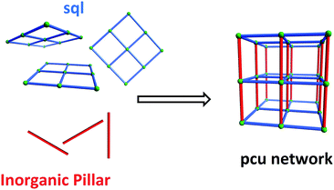 | ||
| Scheme 1 Self-assembly of pillared pcu topology networks from sql networks cross-linked by linear inorganic anions that serve as pillars. | ||
Two crystal engineering approaches exist for the formation of networks that exhibit ultramicropores: incorporation of short linkers (<0.7 nm); interpenetration of two or more networks with relatively large cavities that afford much reduced pore size following interpenetration. Interpenetration was initially thought of as a hindrance to gas sorption applications.10 Indeed, the prototypal pcu net that is sustained by DICRO pillars, DICRO-1-M-i, 1 = 4,4′-bipyridine, (M2+ = Fe,11 Co,12 Ni (ref. 13) and Cu;13i = interpenetrated) eschews porosity because of 2-fold interpenetration. Nevertheless, it is becoming apparent that interpenetration, a well-recognised phenomenon,4c can be an effective tool to generate ultramicroporous materials that exhibit high isosteric enthalpy of adsorption (Qst) and high selectivity for polarisable gases.7b
We report herein a family of 2-fold interpenetrated HUMs based upon DICRO pillars: [M(4,4′-azopyridine)2(Cr2O7)]n, DICRO-3-M-i, (3 = 4,4′-azopyridine; M = Co2+, Ni2+, Cu2+, Zn2+). DICRO-3-M-i form pcu topology nets which exhibit offset interpenetration and their pore walls are lined by inorganic moieties, unlike DICRO-2-Ni-i.6a The DICRO-3-M-i family was characterised by single-crystal and powder X-ray diffraction, thermogravimetric analysis (TGA), FT-IR spectroscopy (FTIR), single component gas sorption measurements (CO2 and N2), molecular simulations of CO2 adsorption, and temperature programmed desorption (TPD) experiments coupled with TGA/mass spectrometry (MS). We evaluated the performance of DICRO-3-Ni-i in the context of direct capture of CO2 from air and five other gas mixtures including simulated flue gas. The stability of DICRO-3-Ni-i to atmospheric water vapour was studied via standard accelerated stability tests6b that simulate long-term storage or “shelf-life”.
Results and discussion
Syntheses and characterisation
Single-crystals of DICRO-3-M-i (M = Ni2+, Cu2+, Zn2+) were prepared via slow diffusion of aqueous K2Cr2O7/M(NO3)2 into MeCN solutions of ligand 3 at room temperature. Yellow block-shaped crystals were obtained after one week. Single-crystals of DICRO-3-Co-i were synthesised by heating a sealed vial of reagents dissolved in H2O to 120 °C for 48 h, followed by cooling to 30 °C over 6 h. DICRO-3-Co-i formed as small, block-shaped, dark red coloured crystals that were weakly diffracting. As such, the crystallographic data for DICRO-3-Co-i is of low quality; however, the space group and crystal packing matches the other three compounds in the series. DICRO-3-M-i were also synthesised via direct mixing of reagents to afford powder samples suitable for use in gas sorption studies. All four compounds were found to be stable after one week of exposure to ambient conditions. PXRD data are provided in the ESI; Fig. S1–S4.† Thermogravimetric analyses reveal that all four compounds exhibit thermal stability to a least 200 °C (Fig. S5†). Infrared spectra are presented in Fig. S6.†Structural analysis
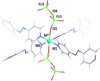
Single-crystal diffraction analysis of DICRO-3-M-i revealed that they are isostructural, crystallising in the triclinic space group P![[1 with combining macron]](https://www.rsc.org/images/entities/char_0031_0304.gif) . The hexacoordinate metal centres serve as six-connected (6-c) nodes in pcu topology networks.14 Four pyridyl groups from four different linker ligands comprise the equatorial plane (Fig. 1) which propagates to the expected sql network. Average M2+–N bond lengths, 2.15 Å (Co), 2.08 Å (Ni), 2.02 Å (Cu) and 2.16 Å (Zn), are consistent with the DICRO-1-M-i family according to data archived in the Cambridge Structural Database (CSD).15 The axial positions of the M2+ centres coordinate to oxygen atoms from Cr2O72− anions, which pillar the sql nets to afford the observed pcu networks. A survey of the CSD revealed that, excluding polyoxometalates, there are only 23 structures of transition metals coordinated to Cr2O72− anions. Of these, 18 structures involve Cr2O72− ligands that are bridging. M2+–O distances of 2.012(7) Å (Co), 2.047(3) Å (Ni), 2.274(4) Å (Cu) and 2.088(2) Å (Zn) are within expected ranges. The Cu–O bonds in DICRO-3-Cu-i are elongated because of Jahn–Teller distortion. Cr ions exhibit tetrahedral geometry with average O–Cr–O angles of 109.65(4)° (Co), 109.20(17)° (Ni), 108.2(2)° (Cu) and 109.24(12)° (Zn). In each compound, the terminal Cr–O bond distances are shorter than the bridging Cr–O distances, which is consistent with previously reported structures.11–13 The Cr(1)–O(4)–Cr(2) angles for DICRO-3-Ni-i, DICRO-3-Cu-i and DICRO-3-Zn-i range between 126.0(2)–127.3(3)° but are more obtuse in DICRO-3-Co-i (135.6(5)°). Crystallographic details and selected bond lengths and angles are summarised in Tables 1 and S1–S2.†
. The hexacoordinate metal centres serve as six-connected (6-c) nodes in pcu topology networks.14 Four pyridyl groups from four different linker ligands comprise the equatorial plane (Fig. 1) which propagates to the expected sql network. Average M2+–N bond lengths, 2.15 Å (Co), 2.08 Å (Ni), 2.02 Å (Cu) and 2.16 Å (Zn), are consistent with the DICRO-1-M-i family according to data archived in the Cambridge Structural Database (CSD).15 The axial positions of the M2+ centres coordinate to oxygen atoms from Cr2O72− anions, which pillar the sql nets to afford the observed pcu networks. A survey of the CSD revealed that, excluding polyoxometalates, there are only 23 structures of transition metals coordinated to Cr2O72− anions. Of these, 18 structures involve Cr2O72− ligands that are bridging. M2+–O distances of 2.012(7) Å (Co), 2.047(3) Å (Ni), 2.274(4) Å (Cu) and 2.088(2) Å (Zn) are within expected ranges. The Cu–O bonds in DICRO-3-Cu-i are elongated because of Jahn–Teller distortion. Cr ions exhibit tetrahedral geometry with average O–Cr–O angles of 109.65(4)° (Co), 109.20(17)° (Ni), 108.2(2)° (Cu) and 109.24(12)° (Zn). In each compound, the terminal Cr–O bond distances are shorter than the bridging Cr–O distances, which is consistent with previously reported structures.11–13 The Cr(1)–O(4)–Cr(2) angles for DICRO-3-Ni-i, DICRO-3-Cu-i and DICRO-3-Zn-i range between 126.0(2)–127.3(3)° but are more obtuse in DICRO-3-Co-i (135.6(5)°). Crystallographic details and selected bond lengths and angles are summarised in Tables 1 and S1–S2.†
| DICRO-3-Co-i | DICRO-3-Ni-i | DICRO-3-Cu-i | DICRO-3-Zn-i | |
|---|---|---|---|---|
| a Torsion angle of C2C3C6C7. b Torsion angle of C12C13C16C17. | ||||
| M II–N1 Å | 2.162(7) | 2.108(3) | 2.036(5) | 2.160(3) |
| M II–N5 Å | 2.142(9) | 2.069(4) | 2.020(5) | 2.161(2) |
| M II–O1 Å | 2.012(7) | 2.047(3) | 2.274(4) | 2.088(2) |
| Cr1–O4–Cr2° | 135.6(5) | 125.9(2) | 127.3(3) | 126.06(16) |
| M II–O1–Cr1 | 154.9(5) | 158.7(2) | 167.0(2) | 163.25(14) |
| Torsion angle of 3 (°) | 61.7,a 57.2b | 105.2,a 94.8b | 62.3,a 72.3b | 77.3,a 64.5b |
| Rhombohedral cavity dimensions (Å) | 8.794, 13.276, 13.314 | 8.734, 13.155, 13.153 | 8.993, 13.014, 13.002 | 8.782, 13.278, 13.270 |
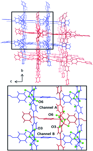
The pcu networks feature rhombohedral cavities with dimensions of ca. 8 × 13 × 13 Å (defined by M⋯M distances) that enable 2-fold interpenetration in which the node of the second net is “offset” from the cavity of the first net (Fig. 2). This mode of interpenetration is commonly encountered in 2-fold interpenetrated pcu networks and is also seen in DICRO-1-M-i.11–13 The offset arrangement could be an artifact of C–H⋯O interactions between pyridyl groups of one network and the Cr2O72− pillars of the adjacent network (Fig. S7–S8†).
Notably, offset interpenetration results in four crystallographically distinct channels running through the structure parallel to the a-axis. However, only two of these channels are large enough to accommodate even small guest molecules. Channels A and B (Fig. 2) exhibit pore diameters of 4.4–5.8 Å and 3.0–3.4 Å, respectively, based upon the closest O⋯O and C⋯C distances for channels A and B respectively (minus van der Waals radii). The larger of the two channels is lined by terminal O-atoms from Cr2O72− pillars (O6) that orient towards the inside of the channel. For channel B, the terminal O-atom (O3) does not protrude into the cavity. The location of accessible O-atoms from the dichromate inorganic pillars in these networks could be of significance with respect to gas sorption, as discussed earlier and below. Channel A has features that resemble a member of the MFSIX platform, [Cu(L)2(SiF6)] (L = 1,2-bis(4-pyridyl)acetylene), SIFSIX-2-Cu-i,7b which displays centred, 2-fold interpenetration and one type of channel. This is because the staggered disposition of the interpenetrated nets results in electronegative atoms (O-atoms in the case of DICRO, F-atoms in the case of SIFSIX) protruding into the channel walls in such a manner that the electronegative atoms are 7–8 Å apart. These features are discussed in relation to gas sorption and isosteric enthalpy of adsorption in the next section.
Gas sorption analyses
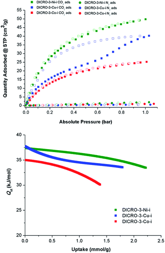
Single component CO2 and N2 sorption measurements were performed on DICRO-3-Ni-i, DICRO-3-Co-i and DICRO-3-Cu-i to determine gas uptake, ideal selectivity and isosteric enthalpy of adsorption (Qst). PXRD patterns reveal that DICRO-3-Zn-i loses crystallinity with loss of solvent and it also exhibits low uptake of N2 at 77 K and CO2 at 195 K (Fig. S9 and S10†). DICRO-3-Zn-i was therefore not studied further in terms of gas sorption. The permanent porosities of DICRO-3-Co-i, DICRO-3-Ni-i and DICRO-3-Cu-i were established by N2 isotherms at 77 K (Fig. S9†). The apparent BET surface area was calculated to be 142, 388 and 325 m2 g−1 for DICRO-3-Co-i, DICRO-3-Ni-i and DICRO-3-Cu-i, respectively. Pore volumes of 0.052, 0.143 and 0.122 cm3 g−1 for DICRO-3-Co-i, DICRO-3-Ni-i, and DICRO-3-Cu-i were calculated by assuming liquid filling of N2 at the P/P0 = 0.95. These values are similar to those calculated from the crystallographic data using PLATON16 for DICRO-3-Ni-i and DICRO-3-Cu-i (0.158 and 0.151 cm3 g−1, respectively). The lower uptake exhibited by DICRO-3-Co-i could be attributed to partial collapse of the network following activation.CO2 and N2 sorption isotherms at 273, 283 and 293 K were collected for DICRO-3-Co-i, DICRO-3-Ni-i and DICRO-3-Cu-i. 293 K isotherms for both gases are presented in Fig. 3 (top), while 273, 283 and 293 K isotherms are given in the ESI (Fig. S11–S13†). A summary of gas sorption data is also provided in Table 2. DICRO-3-Co-i and DICRO-3-Ni-i both exhibit type I isotherms for CO2 sorption whereas DICRO-3-Cu-i has a distinct step and hysteresis. The step observed in the CO2 adsorption isotherms for DICRO-3-Cu-i varies with temperature, occurring at higher partial pressures and becoming more gradual at higher temperature. The stepped nature of the isotherm observed for DICRO-3-Cu-i may be due to either of two structural changes: translation of independent networks with respect to one another upon increased CO2 sorption, a phenomenon that has been reported previously for similar systems;17 flexible networks switching between a narrow pore (NP) and a large pore (LP) form, which has also been observed in pcu networks.17b,18 Since, stepped isotherms were not observed for the Co, Ni and Zn analogues it seems unlikely that translation of independent networks is the origin for the stepped behaviour seen in DICRO-3-Cu-i. Cu2+ exhibits Jahn–Teller distortion, which is known to be temperature dependent (the distortion is less pronounced at higher temperatures). The stepped nature of the isotherm could therefore be a consequence of the effect of Jahn–Teller distortion upon the coordination sphere, which would in turn affect the pore size and shape. To verify this hypothesis, PXRD experiments were conducted on ‘as-synthesised’ powder at ambient pressure, at reduced pressure and again after the powder was cycled back to ambient pressure. A phase change is apparent from the PXRD patterns (Fig. S14†) but attempts to collect diffraction data on single-crystals of DICRO-3-Cu-i at reduced pressure were unsuccessful.
| Calculated void spacea | Calculated micropore volume (cm3 g−1) | CO2/N2 selectivity atb 293 K | CO2 | N2 | |||||
|---|---|---|---|---|---|---|---|---|---|
| Micropore volumec (195 K) | Q st at low loading (kJ mol−1) | Uptake (cm3 g−1) at 293 K 0.1/1 bar | Micropore volumed (77 K) | BET exp. (m2 g−1) at 77 K | Uptake (cm3 g−1) at 293 K, 1 bar | ||||
| a The accessible void space and micropore volume were calculated with the program PLATON using a probe radius of 1.2 Å. b Preliminary selectivity values were calculated as a ratio of gas uptakes at a specified pressure and 293 K from single component N2 and CO2 data. Langmuir curves were fitted to CO2 isotherms and used to calculate uptake at pressure of 0.85 bar, linear curves were fitted to N2 data and uptake calculated at 0.15 bar. c (DR method) [cm3 g−1]. d (t-Plot) exp. [cm3 g−1]. | |||||||||
| DICRO-3-Co-i | 28.2% | 0.201 | 70.2 | 0.054 | 35 | 8.58/25.20 | 0.052 | 142 | 1.01 |
| DICRO-3-Ni-i | 22.6% | 0.158 | 79.3 | 0.109 | 37 | 18.59/49.76 | 0.143 | 388 | 1.95 |
| DICRO-3-Cu-i | 21.9% | 0.151 | 145.9 | 0.072 | 37 | 10.75/40.26 | 0.122 | 325 | 0.51 |
Selectivity for CO2 over N2 (SCN) for DICRO-3-Co-i, DICRO-3-Ni-i and DICRO-3-Cu-i was calculated from the uptakes of CO2 at 0.15 bar and N2 at 0.85 bar at 293 K to be 70.2, 79.3 and 145.9, respectively. The relatively high SCN for DICRO-3-Cu-i is partly a result of its very low N2 uptake at 293 K. Such SCN values are comparable to porous MOMs containing amino-functional groups and open-metal sites, which are absent herein.19
CO2 isotherms measured at 273, 283 and 293 K were fitted using the virial equation (Fig. S15, S17, S19†), and the isosteric enthalpy of adsorption (Qst) was calculated using the Clausius–Clapeyron equation.20Qst values at low loading for DICRO-3-Co-i, DICRO-3-Ni-i and DICRO-3-Cu-i are 35, 37 and 37 kJ mol−1, respectively (Fig. S16, S18, S20†). The relatively flat shape of the Qst curves indicates that the binding energy is relatively independent of loading. As mentioned earlier, SIFSIX-2-Cu-i exhibits similar pore size, shape and chemistry to channel A of the DICRO-3-M-ifamily. Qst values at mid-loading (SIFSIX-2-Cu-i = 35 kJ mol−1; DICRO-3-Cu-i = 35 kJ mol−1) and curve shapes are indeed comparable. Qst values for DICRO-3-M-iare also similar or higher than seen for MOF-5 (34 kJ mol−1),21HKUST-1 (35 kJ mol−1),22MAF-25 (26 kJ mol−1),23InOF-1 (29 kJ mol−1)24 and NOTT-140 (25 kJ mol−1).25 However HUMs with mmo topology exhibit narrower pores and much higher Qst values at low loading: MOOFOUR-1-Ni (56 kJ mol−1),9bCROFOUR-1-Ni (50 kJ mol−1)9b and WOFOUR-1-Ni (65 kJ mol−1).9a Comparison can also be made with DICRO-2-Ni-i, for which the pore diameter (3.6 Å) is intermediate to those of channels A and B of DICRO-3-M-i. The Cr2O72− pillar is directed away from the accessible channel in DICRO-2-Ni-ibut towards the interior of the channel in DICRO-3-M-i. The larger Qst values of DICRO-3-M-ivs.DICRO-2-Ni-i (30.5 kJ mol−1)6a support the importance of pore size and pore chemistry seen for the MFSIX platform.7b While interpenetration necessarily reduces pore dimensions, likely enhancing binding interactions between sorbate and sorbent, interpenetration may also afford non-uniform pores and significantly change pore structure. Whereas uniform pore binding is likely to be generally preferred for enhanced selectivity, different sorbates could require very different pore structures to optimise the energetics of binding. Therefore, generalisation about the influence of interpenetration upon separations is inappropriate since interpenetrated networks may in some circumstances be more able to create uniform pores than their non-interpenetrated analogues.
Molecular simulations
Molecular simulations of CO2 adsorption for DICRO-3-Ni-i and DICRO-3-Cu-i indicate that guest CO2 molecules are adsorbed into both channels A and B and that, at CO2 saturation, CO2 molecules interact with exposed oxygen atoms of the Cr2O72− pillar (Fig. 4). The tight fit within the channels and the presence of exposed oxygen atoms from Cr2O72− pillars, contributes to the relatively high zero loading CO2Qst for these HUMs. Simulations of CO2 adsorption at 273, 283 and 293 K were performed for DICRO-3-Ni-i and DICRO-3-Cu-i. For DICRO-3-Ni-i isotherms are in good agreement with the experimental data (Fig. S21†). However, for DICRO-3-Cu-i simulated CO2 isotherms correspond well with experimental data only in the low and high-pressure regions of the isotherms for the three temperatures, i.e., before and after the inflection point in the experimental isotherms (Fig. S22†). The simulated Qst values are also in good agreement with experiment at 32.8 (vs. 37) and 33.5 kJ mol−1 (vs. 37) for DICRO-3-Ni-i and DICRO-3-Cu-i, respectively (Fig. S23, S24†). The simulations for DICRO-3-Cu-i do not show the inflection point from the experimental CO2 isotherms because the HUM is treated as a rigid network in the simulations. The simulations indicate that the X-ray crystal structure for DICRO-3-Cu-i is representative of the structure occurring after the step (at higher pressure) in the experimental isotherms.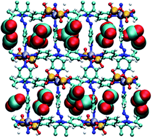 | ||
| Fig. 4 Simulated packing of CO2 guest molecules in DICRO-3-M-i. View down a-axis. Light blue (carbon), red (oxygen), blue (nitrogen), yellow (chromium), purple (M2+), white (hydrogen). | ||
Accelerated stability and temperature programmed desorption
Because of its relatively high CO2 uptake and Qst, DICRO-3-Ni-i was selected for testing regarding its stability and ability to uptake CO2 directly from the atmosphere, as well as under simulated flue gas conditions. The stability of DICRO-3-Ni-i to atmospheric water vapour was evaluated via accelerated stability testing,6b which simulates long-term storage and shelf-life (see ESI for full details and Fig S27–S29†). The surface area of DICRO-3-Ni-i was found to decrease upon increased exposure. An as-synthesised sample exhibited a BET surface area of 388 m2 g−1, while surface areas for 1 day, 7 days and 16 days were 289 m2 g−1 (−25%), 255 m2 g−1 (−34%) and 173 m2 g−1 (−55%), respectively. The stability of DICRO-3-Ni-i is comparable to HKUST-1 (−28% surface area following 1 day exposure; −33% after 7 days) but superior to Mg-MOF-74 (−74% surface area following 1 day exposure).6b The performance of DICRO-3-Ni-i for capturing CO2 directly from air and under conditions resembling flue gas streams was also evaluated. TGA/MS was used to determine quantitative uptakes of specific adsorbents from these gas streams (full details given in ESI). DAC measurements on DICRO-3-Ni-i revealed a CO2 uptake of ∼0.97 L CO2 per kg (∼2 mg CO2 per g solid) when exposed to the laboratory atmosphere for 12 h (see Fig. S30† for schematic diagram of DAC/TPD apparatus; all TPD and uptake plots are located in Fig. S32–S40 and data tabulated in Table S9†). This equates to a SCW CO2![[thin space (1/6-em)]](https://www.rsc.org/images/entities/char_2009.gif) :
:![[thin space (1/6-em)]](https://www.rsc.org/images/entities/char_2009.gif) H2O ratio of >2%
H2O ratio of >2%![[thin space (1/6-em)]](https://www.rsc.org/images/entities/char_2009.gif) :
:![[thin space (1/6-em)]](https://www.rsc.org/images/entities/char_2009.gif) <97% in terms of mass uptake for each component, which is above that measured for HKUST-1 (1%
<97% in terms of mass uptake for each component, which is above that measured for HKUST-1 (1%![[thin space (1/6-em)]](https://www.rsc.org/images/entities/char_2009.gif) :
:![[thin space (1/6-em)]](https://www.rsc.org/images/entities/char_2009.gif) 99%) but lower than that of SIFSIX-3-Ni (8%
99%) but lower than that of SIFSIX-3-Ni (8%![[thin space (1/6-em)]](https://www.rsc.org/images/entities/char_2009.gif) :
:![[thin space (1/6-em)]](https://www.rsc.org/images/entities/char_2009.gif) 92%) and Mg-MOF-74 (4%
92%) and Mg-MOF-74 (4%![[thin space (1/6-em)]](https://www.rsc.org/images/entities/char_2009.gif) :
:![[thin space (1/6-em)]](https://www.rsc.org/images/entities/char_2009.gif) 96%).6b Under simulated flue gas conditions (moist CO2, 0.15 atm), DICRO-3-Ni-i exhibits high uptake of CO2, ∼9.77 L CO2 per kg (19.2 mg CO2 per g solid) (Fig. 5). This equates to a SCW CO2
96%).6b Under simulated flue gas conditions (moist CO2, 0.15 atm), DICRO-3-Ni-i exhibits high uptake of CO2, ∼9.77 L CO2 per kg (19.2 mg CO2 per g solid) (Fig. 5). This equates to a SCW CO2![[thin space (1/6-em)]](https://www.rsc.org/images/entities/char_2009.gif) :
:![[thin space (1/6-em)]](https://www.rsc.org/images/entities/char_2009.gif) H2O ratio of 53%
H2O ratio of 53%![[thin space (1/6-em)]](https://www.rsc.org/images/entities/char_2009.gif) :
:![[thin space (1/6-em)]](https://www.rsc.org/images/entities/char_2009.gif) 47% which is higher than that of HKUST-1 (8.5%
47% which is higher than that of HKUST-1 (8.5%![[thin space (1/6-em)]](https://www.rsc.org/images/entities/char_2009.gif) :
:![[thin space (1/6-em)]](https://www.rsc.org/images/entities/char_2009.gif) >91%); slightly higher than to that of Mg-MOF-74 (51%
>91%); slightly higher than to that of Mg-MOF-74 (51%![[thin space (1/6-em)]](https://www.rsc.org/images/entities/char_2009.gif) :
:![[thin space (1/6-em)]](https://www.rsc.org/images/entities/char_2009.gif) 49%) and second only to SIFSIX-3-Ni (62%
49%) and second only to SIFSIX-3-Ni (62%![[thin space (1/6-em)]](https://www.rsc.org/images/entities/char_2009.gif) :
:![[thin space (1/6-em)]](https://www.rsc.org/images/entities/char_2009.gif) 38%) when tested under the same conditions.6b TPD experiments revealed that desorption occurs below 50 °C for DICRO-3-Ni-i, which is relatively easier than both HKUST-1 and Mg-MOF-74.
38%) when tested under the same conditions.6b TPD experiments revealed that desorption occurs below 50 °C for DICRO-3-Ni-i, which is relatively easier than both HKUST-1 and Mg-MOF-74.
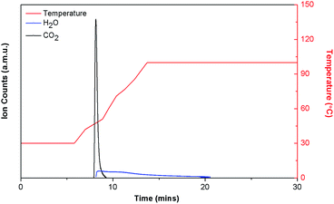 | ||
| Fig. 5 TPD plot for DICRO-3-Ni-i exposed to moist 0.15 atm CO2. Uptake equal to 19.2 mg CO2 per g, ∼52.7% CO2, ∼47.3% H2O. | ||
Conclusions
A family of 3D Hybrid Ultramicroporous Materials (HUMs), DICRO-3-M-i, with four members has been synthesised using a crystal engineering approach that exploits Cr2O72− anions to pillar square lattice networks (sql) constructed from 4,4′-azopyridine organic linkers (3) and M2+ metal centres. Single component gas sorption measurements for three of these compounds, DICRO-3-Co-i, DICRO-3-Ni-i and DICRO-3-Cu-i, were collected and reveal permanent microporosity, selective CO2/N2 uptake and relatively high Qst values towards CO2. Temperature programmed desorption experiments conducted on DICRO-3-Ni-i revealed excellent CO2 uptake and SCN when exposed to flue gas conditions. Structural analysis, gas sorption experiments and molecular simulations from this study reaffirm that HUMs can afford favourable sorbate–sorbent interactions. Specifically, for the DICRO-3-M-i family, Cr2O72− anions orient in such a manner that terminal O-atoms line the walls of the accessible 1D ultramicroporous channels, resulting in high Qst and enhanced CO2 sorption performance.To conclude, whereas we have not yet elucidated the origin of the flexibility in this family of materials, there are four take-home messages that could aid the custom-design of porous materials with enhanced gas sorption performance: the combination of ultramicropores and strong electrostatics in HUMs necessarily leads to tight binding sites for polarisable guests such as CO2; interpenetration can be used to facilitate ultramicropores, but may also generate non-uniform pores; the presence of groups with strong electrostatics alone is not sufficient, but rather these groups must be favourably positioned to achieve optimal guest binding; binding energies of 35–40 kJ mol−1 enable facile regeneration of these sorbents.
Acknowledgements
This publication emanates from research conducted with financial support from the Science Foundation Ireland under the International Strategic Cooperation Award Grant Number SFI/13/ISCA/2845. Additionally, M. J. Z. acknowledges Science Foundation Ireland for support (SFI Award 13/RP/B2549). B. S. acknowledges the (Award No. CHE-1152362). Computational resources were made available by XSEDE Grant No. TG-DMR090028. The use of the services provided by Research Computing at the University of South Florida is also acknowledged.Notes and references
- (a) G. R. Desiraju, The Design of Organic Solids, Elsevier, Amsterdam, 1989 Search PubMed; (b) B. Moulton and M. J. Zaworotko, Chem. Rev., 2001, 101, 1629 CrossRef CAS PubMed.
- (a) A. F. Wells, Three Dimensional Nets and Polyhedra, Wiley, New York, 1977 Search PubMed; (b) B. F. Hoskins and R. Robson, J. Am. Chem. Soc., 1990, 112, 1546 CrossRef CAS; (c) B. F. Hoskins and R. Robson, J. Am. Chem. Soc., 1989, 111, 5962 CrossRef CAS.
- J. J. Perry IV, J. A. Perman and M. J. Zaworotko, Chem. Soc. Rev., 2009, 38, 1400 RSC.
- (a) S. R. Batten, S. M. Neville and D. R. Turner, Coordination Polymers Design, Analysis and Application Introduction, RSC Publishing, Cambridge, UK, 2009 Search PubMed; (b) S. Kitagawa, R. Kitaura and S. Noro, Angew. Chem., Int. Ed., 2004, 43, 2334 CrossRef CAS PubMed; (c) S. R. Batten and R. Robson, Angew. Chem., Int. Ed., 1998, 37, 1460 CrossRef.
- (a) Metal–Organic Frameworks: Applications from Catalysis to Gas Storage, ed. D. Farrusseng, Wiley-VCH Verlag GmbH & Co, Weinheim, 2011 Search PubMed; (b) Metal–Organic Frameworks: Design and Application, ed. L. R. MacGillivray, John Wiley & Sons, Hoboken, USA, 2010 Search PubMed; (c) Functional Metal–Organic Frameworks: Gas storage, separation and catalysis, ed. M. Schröder, Springer-Verlag, Berlin, 2009 Search PubMed.
- (a) H. S. Scott, A. Bajpai, K. J. Chen, T. Pham, B. Space, J. J. Perry IV and M. J. Zaworotko, Chem. Commun., 2015, 51, 14832 RSC; (b) A. Kumar, D. G. Madden, M. Lusi, K. J. Chen, E. A. Daniels, T. Curtin, J. J. Perry IV and M. J. Zaworotko, Angew. Chem., Int. Ed., 2015, 54, 14372 CrossRef CAS PubMed.
- (a) S. K. Elsaidi, M. H. Mohamed, H. T. Schaef, A. Kumar, M. Lusi, T. Pham, K. A. Forrest, B. Space, W. Xu, G. J. Halder, J. Liu, M. J. Zaworotko and P. K. Thallapally, Chem. Commun., 2015, 51, 15530 RSC; (b) P. Nugent, Y. Belmabkhout, S. D. Burd, A. J. Cairns, R. Luebke, K. Forrest, T. Pham, S. Q. Ma, B. Space, L. Wojtas, M. Eddaoudi and M. J. Zaworotko, Nature, 2013, 495, 80 CrossRef CAS PubMed; (c) O. Shekhah, Y. Belmabkhout, K. Adil, P. M. Bhatt, A. J. Cairns and M. Eddaoudi, Chem. Commun., 2015, 51, 13595 RSC; (d) O. Shekhah, Y. Belmabkhout, Z. J. Chen, V. Guillerm, A. Cairns, K. Adil and M. Eddaoudi, Nat. Commun., 2014, 5, 1 Search PubMed.
- (a) S. D. Burd, S. Q. Ma, J. A. Perman, B. J. Sikora, R. Q. Snurr, P. K. Thallapally, J. Tian, L. Wojtas and M. J. Zaworotko, J. Am. Chem. Soc., 2012, 134, 3663 CrossRef CAS PubMed; (b) S. Noro, S. Kitagawa, M. Kondo and K. Seki, Angew. Chem., Int. Ed., 2000, 39, 2082 CrossRef CAS; (c) P. Nugent, V. Rhodus, T. Pham, B. Tudor, K. Forrest, L. Wojtas, B. Space and M. Zaworotko, Chem. Commun., 2013, 49, 1606 RSC.
- (a) M. H. Mohamed, S. K. Elsaidi, T. Pham, K. A. Forrest, B. Tudor, L. Wojtas, B. Space and M. J. Zaworotko, Chem. Commun., 2013, 49, 9809 RSC; (b) M. H. Mohamed, S. K. Elsaidi, L. Wojtas, T. Pham, K. A. Forrest, B. Tudor, B. Space and M. J. Zaworotko, J. Am. Chem. Soc., 2012, 134, 19556 CrossRef CAS PubMed.
- N. L. Rosi, M. Eddaoudi, J. Kim, M. O'Keeffe and O. M. Yaghi, Angew. Chem., Int. Ed., 2002, 41, 284 CrossRef CAS.
- X. Y. Chen, B. Zhao, P. Cheng, B. Ding, D. Z. Liao, S. P. Yan and Z. H. Zhiang, Eur. J. Inorg. Chem., 2004, 562 CrossRef CAS.
- Y. Hayashi, T. Tagami, H. Mano and A. Uehara, Chem. Lett., 2001, 30, 562 CrossRef.
- A. L. Kopf, P. A. Maggard, C. L. Stern and K. R. Poeppelmeier, Acta Crystallogr., Sect. C: Cryst. Struct. Commun., 2005, 61, M165 Search PubMed.
- Topology determined using the computer program TOPOS: V. A. Blatov, A. P. Shevchenko and D. M. Proserpio, Cryst. Growth Des., 2014, 14, 3576 CAS.
- F. H. Allen, Acta Crystallogr., Sect. B: Struct. Sci., 2002, 58, 380 CrossRef.
- A. L. Spek, J. Appl. Crystallogr., 2003, 36, 7 CrossRef CAS.
- (a) K. L. Mulfort, O. K. Farha, C. D. Malliakas, M. G. Kanatzidis and J. T. Hupp, Chem.–Eur. J., 2010, 16, 276 CrossRef CAS PubMed; (b) S. Kitagawa and K. Uemura, Chem. Soc. Rev., 2005, 34, 109 RSC.
- T. Devic, P. Horcajada, C. Serre, F. Salles, G. Maurin, B. Moulin, D. Heurtaux, G. Clet, A. Vimont, J. M. Greneche, B. Le Ouay, F. Moreau, E. Magnier, Y. Filinchuk, J. Marrot, J. C. Lavalley, M. Daturi and G. Ferey, J. Am. Chem. Soc., 2010, 132, 1127 CrossRef CAS PubMed.
- (a) B. Arstad, H. Fjellvag, K. O. Kongshaug, O. Swang and R. Blom, Adsorption, 2008, 14, 755 CrossRef CAS; (b) K. J. Chen, R. B. Lin, P. Q. Liao, C. T. He, J. B. Lin, W. Xue, Y. B. Zhang, J. P. Zhang and X. M. Chen, Cryst. Growth Des., 2013, 13, 2118 CrossRef CAS; (c) R. Vaidhyanathan, S. S. Iremonger, K. W. Dawson and G. K. H. Shimizu, Chem. Commun., 2009, 45, 5230 RSC.
- F. Rouquerol, J. Rouquerol, K. S. W. Sing, P. Lllewellyn and G. Maurin, Adsorption by Powders and Porous Solids: Principles, Methodology and Applications, Academic Press, Amsterdam, 2nd edn, 2014 Search PubMed.
- Z. X. Zhao, Z. Li and Y. S. Lin, Ind. Eng. Chem. Res., 2009, 48, 10015 CrossRef CAS.
- Q. Y. Yang, C. Y. Xue, C. L. Zhong and J. F. Chen, AIChE J., 2007, 53, 2832 CrossRef CAS.
- J. B. Lin, J. P. Zhang and X. M. Chen, J. Am. Chem. Soc., 2010, 132, 6654 CrossRef CAS PubMed.
- J. J. Qian, F. L. Jiang, D. Q. Yuan, M. Y. Wu, S. Q. Zhang, L. J. Zhang and M. C. Hong, Chem. Commun., 2012, 48, 9696 RSC.
- C. R. Tan, S. H. Yang, N. R. Champness, X. A. Lin, A. J. Blake, W. Lewis and M. Schröder, Chem. Commun., 2011, 47, 4487 RSC.
Footnotes |
| † Electronic supplementary information (ESI) available: PXRD, TGA, FT-IR, molecular simulations, structural and sorption data. CCDC 1468766–1468769. For ESI and crystallographic data in CIF or other electronic format see DOI: 10.1039/c6sc01385f |
| ‡ H. S. S. and N. O. contributed equally. |
| This journal is © The Royal Society of Chemistry 2016 |

