
 Open Access Article
 This Open Access Article is licensed under a
 Creative Commons Attribution 3.0 Unported Licence
Noble-metal-free Co3S4–S/G porous hybrids as an efficient electrocatalyst for oxygen reduction reaction†
Wenling
Gu
ac,
Liuyong
Hu
bc,
Wei
Hong
ac,
Xiaofang
Jia
a,
Jing
Li
*a and
Erkang
Wang
*a
aState Key Laboratory of Electroanalytical Chemistry, Changchun Institute of Applied Chemistry, Chinese Academy of Sciences, Changchun, Jilin 130022, PR China. E-mail: ekwang@ciac.ac.cn
bState Key Laboratory of Polymer Physics and Chemistry, Changchun Institute of Applied Chemistry, Chinese Academy of Sciences, Changchun, Jilin 130022, PR China
cUniversity of the Chinese Academy of Sciences, Beijing, 100049, PR China
First published on 2nd March 2016
Abstract
Developing of a new noble-metal-free catalyst to replace Pt-based catalysts of the oxygen reduction reaction (ORR) both in alkaline and acidic conditions is extremely significant for the fuel cell. In this paper, based on the pyrolysis of an inexpensive precursor cobalt dithiolene (a S4-chelate complex) on simultaneously reduced graphene oxide (GO) as a support matrix, a high-efficiency noble-metal-free hybrid for oxygen reduction reaction (ORR) consisting of Co3S4 nanoparticles encapsulated in porous sulfur doped graphene (referred as Co3S4–S/G) was fabricated. The catalyst obtained at 800 °C (Co3S4–S/G-800) manifests excellent oxygen reduction activity. Of note, the Co3S4–S/G-800 hybrids also exhibited prominent ORR activity with high selectivity (mainly 4e− reaction process) and very low H2O2 yield in acidic electrolyte. The optimal Co3S4–S/G-800 hybrid displayed much greater tolerance to methanol and higher stability than that of Pt/C. These admirable performances endorse Co3S4–S/G-800 electrocatalyst holding great potential for fuel cells. Meanwhile, this work also provides a simple and practical method to fabricate cobalt chalcogenides by using the cost-effective and easily synthesized S4-chelate complex.
Introduction
With the rapid development of technology energy demand grows continuously. As a high energy-conversion efficiency technique, fuel cells have attracted much attention in recent years.1 The oxygen reduction reaction (ORR) is a crucial step in high energy-conversion devices. However, the sluggish cathodic reaction of ORR often needs the assistance of an efficient electrocatalyst.2 Among these electrocatalysts, Pt and Pt-based alloy materials3–5 have exhibited remarkable performance for ORR. Nevertheless, their high price, their scarcity, and especially low stability for methanol crossover have limited their widespread use.6 Correspondingly, much effort has been made to design and synthesize non-precious metal electrocatalysts (NPMCs) as alternatives to Pt, such as heteroatom-doped carbon materials, metal–Nx macrocycles, metal oxides supported on graphene, metal chalcogenides etc.7–10 Since Jasinski discovered that cobalt phthalocyanine (an N4-chelate macrocycle) possessed good ORR activity in alkaline conditions,11 metal–N4 macrocycles based catalysts (M–N4/C) have received much attention owing to the highly active site of surface nitrogen associated with metal.12–20 Müllen et al.13 made another attempt to obtain a [CoN4]3/C electrocatalyst by using a new class of metal–N4 macrocyclic complexes as a precursor, which showed high catalyst activity and durability for ORR in alkaline conditions. Niu's group14 had reported that by pyrolyzing a mixture of cyanocobalamin (an N4-chelate macrocycle, vitamin B12) and GO, an excellent electrocatalyst was fabricated with a positive onset potential and high durability for ORR in alkaline electrolyte. Although excellent activity of M–N4/C based catalysts has been obtained in alkaline conditions, only few of these catalysts were found to retain catalyst activity in acidic conditions, mostly owing to the low amounts of catalytic sites of these catalysts. Moreover, these macrocycles still suffer from high-price and complicated synthetic processes which significantly influences their practical application.In this work, inspired by the excellent electrocatalytic activity of M–N4/C catalysts and the special structure of the N4-chelate macrocycles, we proposed to use the cost-effective and easily fabricated metal–S4 complex of cobalt dithiolene as a cobalt and sulfur rich precursor for obtaining high-performance ORR catalysts for the first time. By facile pyrolysis of the cobalt dithiolene and GO (which acts as a support carbon matrix) at 800 °C, a non-precious metal electrocatalyst of Co3S4 nanoparticles encapsulated in porous sulfur-doped graphene (Co3S4–S/G-800) was obtained. As far as we know, cobalt chalcogenides (such as Co1−xS, CoS, Co3S4, Co9S8) had been shown to display higher chemical stability, electrical conductivity and electrocatalytic activity than other metal chalcogenides.21,22 With such outstanding advantages, they have been extensively applied in many fields, such as optoelectronic devices, energy storage, magnetic devices and electrocatalysis. In addition, theoretical studies also predicted that cobalt chalcogenides have great potential in ORR.23 However, most recently reported cobalt chalcogenide based ORR catalysts required complicated and time-consuming synthesis processes and showed far lower electrocatalytic activity than the commercial Pt/C catalyst. Herein, the obtained Co3S4–S/G-800 hybrid was found to be a highly effective and robust catalyst to boost ORR. Co3S4–S/G-800 also showed better electrochemical durability and tolerance toward methanol than commercial Pt/C. To our surprise, the ORR activity of Co3S4–S/G-800 was superior to most recently reported cobalt sulfide nanoparticles or other heteroatom based electrocatalysts both in alkaline and acidic conditions.21–28 All these results demonstrate that the obtained Co3S4–S/G-800 is a promising electrocatalyst for fuel cells and that the pure S4-chelate complex can be used to replace the high-price N4-chelate macrocycles (such as cyanocobalamin, phthalocyanine, porphyrins etc.) for designing high-performance ORR catalysts. Meanwhile, this work also provides a simple and practical method to fabricate cobalt chalcogenides.
Results and discussion
Fig. 1 depicts the chemical structure of the cobalt dithiolene (which can be easily obtained by a one-step process), the synthetic process of the Co3S4–S/G and the corresponding photograph of the catalyst. It is well known that the carbonization temperature is a key factor to influence the performance of the catalysts on ORR, since a low pyrolysis temperature will facilitate the incorporation of activated elements into the carbon skeleton and a high temperature may effectively increase electrical conductivity of the catalysts.29 Therefore, the catalysts were obtained at different pyrolysis temperatures to find the optimum pyrolysis condition. XRD was carried out to analyze the crystal structures of all the as-prepared catalysts at different temperatures. As shown in Fig. S3a,† the presence of a peak around 25° suggested that the ordered graphitic phase was formed at high carbonization temperatures, which was beneficial for the electrical conductivity of the catalysts. Meanwhile, the obtained catalysts showed the typical crystal structure of Co3S4 with the peaks located at 18.38, 30.01, 35.6, 46.6, 52.3 and 54.4°, which correspond to the (111), (220), (311), (400), (511) and (440) planes (JCPDS file: #471738) respectively.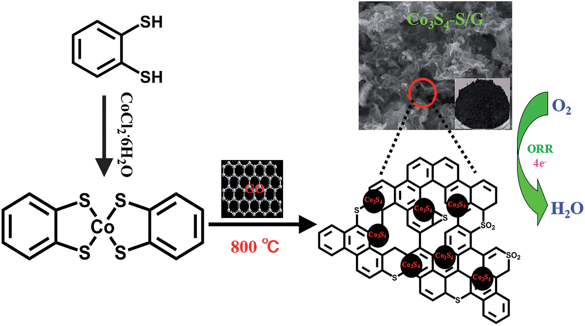 | ||
| Fig. 1 Schematic illustration of the fabrication process of Co3S4–S/G catalysts and electrocatalytic activity for oxygen reduction reaction. | ||
The properties of the derived catalysts were further analyzed by Raman spectra. From Fig. S3b,† two broad bands corresponding to the D-band (∼1350 cm−1) and G-band (∼1580 cm−1) were observed. The D-band is related to the vibrations of the sp3 carbon atoms of disordered graphene nanosheets, while the G-band is attributed to the in-plane vibrations of sp2 carbon atoms of graphite. The ratio of the D band to the G band (ID/IG) varied with the pyrolysis temperatures, with values of 0.967 (600 °C), 0.985 (700 °C), 1.00 (800 °C) and 1.03 (900 °C). The increased ratio of ID/IG proved that the disordered and significant edge sites had been successfully increased by raising the pyrolysis temperature which would effectively enhance the conductivity of the catalysts and help charge localization for O2 chemisorption.30
The morphology of the fabricated Co3S4–S/G catalysts at different pyrolysis temperatures was studied using SEM. As observed in Fig. S4,† raising pyrolysis temperatures from 600 to 900 °C, the Co3S4 nanoparticles were gradually generated and uniformly encased in the derived carbon skeleton. The elemental compositions of prepared Co3S4–S/G catalysts were investigated by XPS and EDX. From Table S1,† the contents of cobalt and sulfur showed decreased trends with increasing pyrolysis temperatures. It is of note that the contents of cobalt and sulfur were found to be lower in the XPS data compared with EDX, which may be caused by the generated carbon layers around the Co3S4 nanoparticles at a higher pyrolysis temperature and the impermeability to carbon layers to XPS for analyzing the cobalt and sulfur elements. However, this phenomenon provided favorable stability to the catalyst in catalytic aspects, especially under some strict conditions. Based on previous reports, although the encapsulated Co3S4 nanoparticles in the carbon layers could not directly contact with the electrolyte, they could activate the outer carbon layers making them more active toward ORR.31
Moreover, in order to explore the influence of the as-obtained catalysts at different temperatures on ORR, the electrochemical experiments were first evaluated by CV and RRDE techniques in 0.1 M KOH (Fig. S5 and 6†) electrolyte. It should be noticed that by comparing the onset potential, half-wave potential as well as current density, the Co3S4–S/G-800 exhibited superior catalytic activity than the samples prepared at other temperatures (Table S2†), implying that the catalyst obtained at 800 °C showed the optimal synergetic effect between the excellent electrical conductivity of the support matrix and the added component. Fig. S7 and Table S3† display the Brunauer–Emmet–Teller (BET) surface areas of all the catalysts, and the Co3S4–S/G-800 showed the largest surface area of 52.44 m2 g−1. In addition, based on the Barrett–Joyner–Halenda (BJH) analysis, the Co3S4–S/G-800 catalyst contained mesopores with a peak at 13 nm, which may exert essential transport ability for ORR relevant substances (O2, H+/OH−, H2O) and provide more active sites.32 It is believed that the relatively larger surface area and existing mesopore feature were both conducive to ORR of Co3S4–S/G-800 catalyst. Therefore, the Co3S4–S/G catalyst discussed below refers to this sample unless otherwise specified.
The TEM image of the Co3S4–S/G-800 (Fig. 2a) showed that the Co3S4 nanoparticles are uniformly distributed in the graphene matrix. Moreover, the HRTEM image (Fig. 2b) and SAED pattern (Fig. 2c) were both investigated to better understand the nanoparticles. The lattice distance of 0.168 nm should correspond to the (440) crystal planes of the Co3S4 phase. Fig. 2d–h show the HAADF-STEM and elemental mapping images of the catalyst. It could be confirmed that the Co3S4 nanoparticles were grown in the graphene matrix and the sulfur element was present not only in Co3S4 nanoparticles, but was also distributed over the support graphene matrix. It is proposed that the Co3S4 nanoparticles originate from the decomposition of cobalt dithiolene at high temperature. Moreover, a part of cobalt dithiolene served as the source of sulfur during the pyrolysis process.
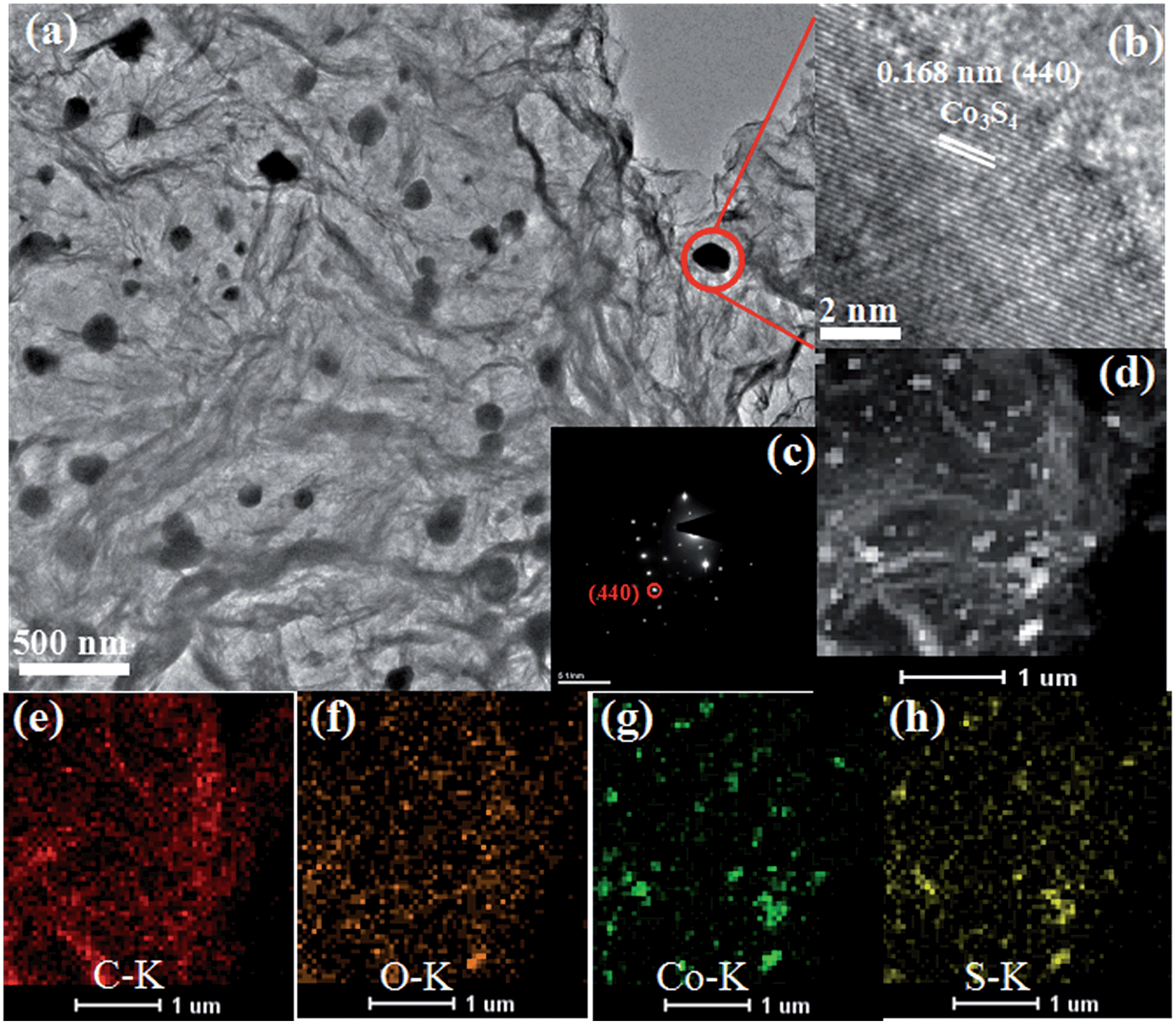 | ||
| Fig. 2 TEM images (a), HRTEM image (b), SAED pattern (c), HAADF-STEM (d) and elemental mapping images (e–h) of Co3S4–S/G-800 catalyst. | ||
The elemental composition of Co3S4–S/G-800 was measured using EDX analysis. As shown in Fig. S8,† the four elements C, O, Co, S were observed. XPS measurements were used to confirm the definite chemical state of the four elements in the Co3S4–S/G-800. Fig. 3a shows the high-resolution C![[thin space (1/6-em)]](https://www.rsc.org/images/entities/char_2009.gif) 1s spectra with the peak located at 286.4 eV which should correspond to the C–S group, along with C–C (291.87 eV) and O–C
1s spectra with the peak located at 286.4 eV which should correspond to the C–S group, along with C–C (291.87 eV) and O–C![[double bond, length as m-dash]](https://www.rsc.org/images/entities/char_e001.gif) O (284.11 eV) groups, indicating the major sp2 carbon atom environments of Co3S4–S/G-800.33 The Co2p spectrum shown in Fig. 3b could be divided into six peaks which were assigned to 2p3/2 of Co2+ and Co3+ ions, 2p1/2 of Co2+ and Co3+ ions, as well as the corresponding satellite peaks, which indicated the presence of Co3S4 nanoparticles. Based on previous reports, the peaks in the S2p spectrum in Fig. 3c at 161.85 and 163.58 eV were assigned to Sn2− and –C–S–C– , respectively,34 while the peak at 169.62 eV was from C–SOx groups. In order to confirm the S signals in the Co3S4–S/G-800 were due to covalent C–S bonds, and did not arise from physically absorbed S, the Co3S4–S/G-800 sample was washed ultrasonically with deionized water or alcohol and remeasured. As expected, the XPS spectra did not exhibit any difference, thus proving the S is doped in the graphene matrix. In addition, from the Raman spectra of the pristine graphene in Fig. S9,† it could be observed the G band occurred at ∼1589 cm−1, while under the same conditions, the G-band for Co3S4–S/G-800 sample appeared at ∼1580 cm−1 (Fig. S3b†). According to the report of Zhu and co-workers,35 it is believed that the matrix of Co3S4–S/G-800 may show n-type doping of graphene. This characteristic, coupled with the XPS results, could strongly certify that the S atoms were doped in the graphene of Co3S4–S/G-800 hybrids via covalent bonds via C–S–C bonds. Indeed, owing to the larger atomic radius of S (103 pm) than C (77 pm), the S doped mesopore catalyst will provide more favorable strains and defects for ORR. Fig. 3d shows the small quantity of oxygen in the Co3S4–S/G-800 hybrids, the residual oxygen may be caused by the incomplete reduction of GO.
O (284.11 eV) groups, indicating the major sp2 carbon atom environments of Co3S4–S/G-800.33 The Co2p spectrum shown in Fig. 3b could be divided into six peaks which were assigned to 2p3/2 of Co2+ and Co3+ ions, 2p1/2 of Co2+ and Co3+ ions, as well as the corresponding satellite peaks, which indicated the presence of Co3S4 nanoparticles. Based on previous reports, the peaks in the S2p spectrum in Fig. 3c at 161.85 and 163.58 eV were assigned to Sn2− and –C–S–C– , respectively,34 while the peak at 169.62 eV was from C–SOx groups. In order to confirm the S signals in the Co3S4–S/G-800 were due to covalent C–S bonds, and did not arise from physically absorbed S, the Co3S4–S/G-800 sample was washed ultrasonically with deionized water or alcohol and remeasured. As expected, the XPS spectra did not exhibit any difference, thus proving the S is doped in the graphene matrix. In addition, from the Raman spectra of the pristine graphene in Fig. S9,† it could be observed the G band occurred at ∼1589 cm−1, while under the same conditions, the G-band for Co3S4–S/G-800 sample appeared at ∼1580 cm−1 (Fig. S3b†). According to the report of Zhu and co-workers,35 it is believed that the matrix of Co3S4–S/G-800 may show n-type doping of graphene. This characteristic, coupled with the XPS results, could strongly certify that the S atoms were doped in the graphene of Co3S4–S/G-800 hybrids via covalent bonds via C–S–C bonds. Indeed, owing to the larger atomic radius of S (103 pm) than C (77 pm), the S doped mesopore catalyst will provide more favorable strains and defects for ORR. Fig. 3d shows the small quantity of oxygen in the Co3S4–S/G-800 hybrids, the residual oxygen may be caused by the incomplete reduction of GO.
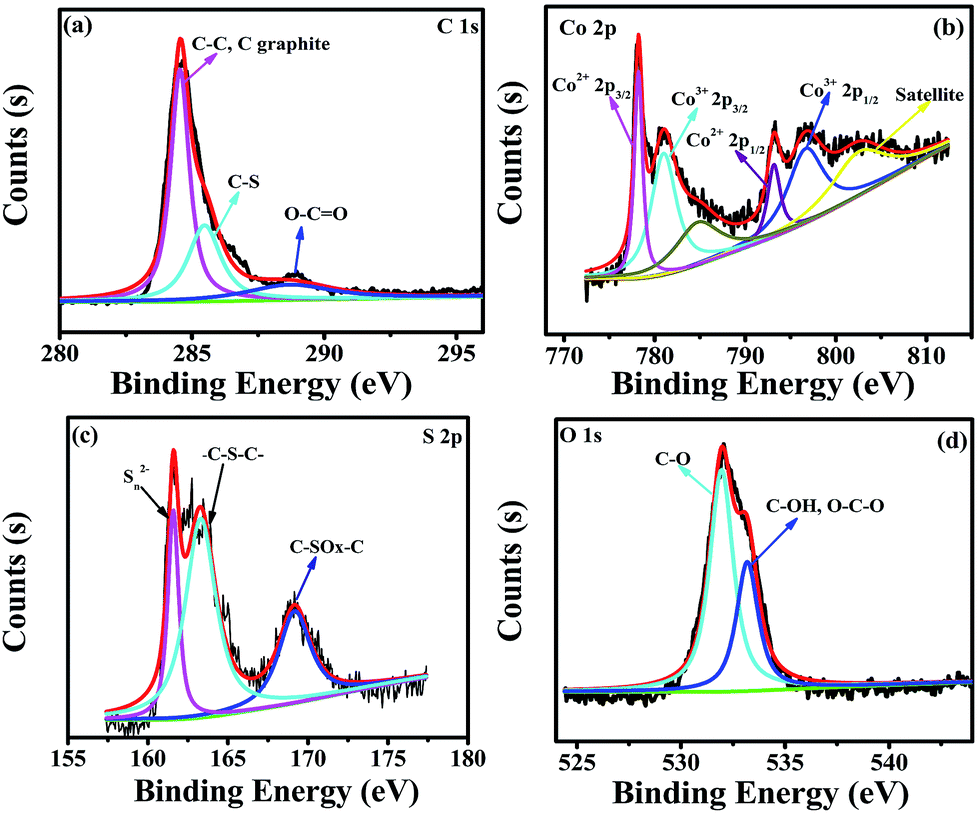 | ||
| Fig. 3 High-resolution C1s XPS spectra (a), Co2p spectra (b), S2p spectra (c) and O1s spectra (d) of the as-obtained Co3S4–S/G-800 hybrids. | ||
To compare the catalyst behavior of Co3S4–S/G-800 relative to commercial Pt/C, typical CV experiments were first carried out in N2 or O2 saturated electrolyte with a potential scan rate of 50 mV s−1. As shown in Fig. 4a, a large cathodic ORR peak of Co3S4–S/G-800 in O2 saturated 0.1 M KOH electrolyte could be easily observed with the onset potential of 0.92 V. In addition, the RRDE voltammograms were further carried out to investigate the ORR catalytic activity of these catalysts. We could see that the Co3S4–S/G-800 expressed nearly identical catalyst activity to Pt/C (Fig. 4b). In general, during the reduction of oxygen, a complete four electron (4e−) reaction process was regarded as more favorable than a two electron (2e−) process, owing to the low hydrogen peroxide yield (H2O2%). Generally, the electrode transfer number and H2O2% were calculated from the tested disk current and ring current. The result (Fig. 4d) showed that the H2O2% of Co3S4–S/G-800 was less than 6% in the potential range from 0.8 to 0 V in the alkaline electrolyte, indicating an almost four electron (4e−) reaction process as found for Pt/C (n ≈ 4.0, Fig. 4c). To further explore the ORR mechanism of the Co3S4–S/G-800 catalyst, RDE measurements were performed. According to the Koutecky–Levich equation, plots of J−1vs. ω−1/2 at different electrode potentials were obtained (the inset of Fig. 4e) and the electrode transfer number can be calculated from the slope of these lines. Values were calculated to be 3.96, 3.99, 4.0 and 4.0 at the potentials of 0.6, 0.5, 0.4 and 0.3 V, respectively, in 0.1 M KOH. These results were in accordance with the RRDE technique, showing a 4e− reaction process for ORR. Fig. 4f shows the Tafel plots of Co3S4–S/G-800 and Pt/C derived from Fig. 4b. Co3S4–S/G-800 has a Tafel slope of 41.56 mV per decade in 0.1 M KOH. In fact, many transition-metal based ORR catalysts after a pyrolysis process possess similar Tafel slopes. Such a Tafel slope proved that the ORR rate determining step should be the splitting of the O–O bands when two electrons moved from active sites to the chemisorbed O2 molecules. Therefore, these values proved that the Co3S4–S/G-800 catalyst had excellent kinetic characteristics for the reduction of oxygen.
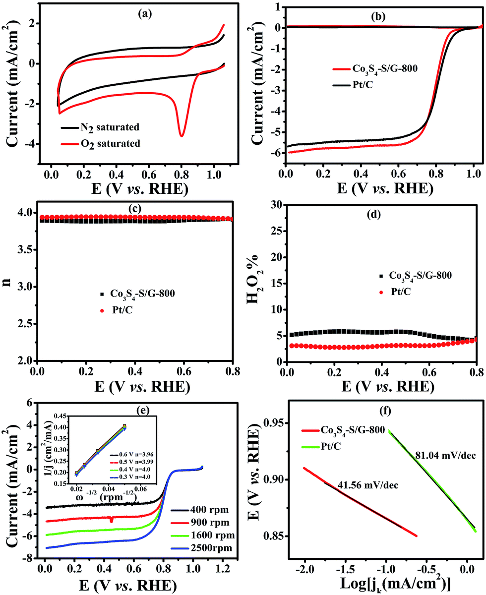 | ||
| Fig. 4 CVs (a) of the Co3S4–S/G-800 nanocatalyst modified electrode in N2 or O2 saturated 0.1 M KOH electrolyte with a potential scan rate of 50 mV s−1; RRDE voltammograms (b), electron transfer number (c), H2O2 yield (d) of the Co3S4–S/G-800 and Pt/C catalysts in O2 saturated 0.1 M KOH electrolyte at a scan rate of 5 mV s−1. The rotation rate is 1600 rpm; RDE voltammograms (e) of the Co3S4–S/G-800 at various rotation rates and the Koutecky–Levich plots (shown as inset). The corresponding Tafel plots (f) of the Co3S4–S/G-800 and Pt/C catalysts. | ||
In contrast, the comparative catalysts of S/G, Co3S4/C-800 (Fig. S10a and b† show the XRD pattern and TEM image) and S/G + Co3S4/C-800 (physical mixture) showed a lower electron transfer number of 3.43–3.62 for S/G, 3.62–3.86 for Co3S4/C-800 and 3.8–3.88 for S/G + Co3S4/C-800 (Fig. 5b), indicating inferior electrocatalysis selectivity and electron transfer ability for these comparative samples. Fig. 5d shows the EIS plots of the comparative catalyst modified electrodes. It was well-known that the semicircle regions at high-ac modulation frequency of the Nyquist plot is related to the electrode transfer process, while the line regions at low-ac modulation frequency represent the diffusion process. Compared with the simple combinations or physical mixture, the Co3S4–S/G-800 catalyst modified electrode exhibited an almost straight line at high-frequency regions, demonstrating the high electric conduction ability of the catalyst and the strong coupling between Co3S4 and S/G, which significantly affected the electronic structure of the support graphene matrix.
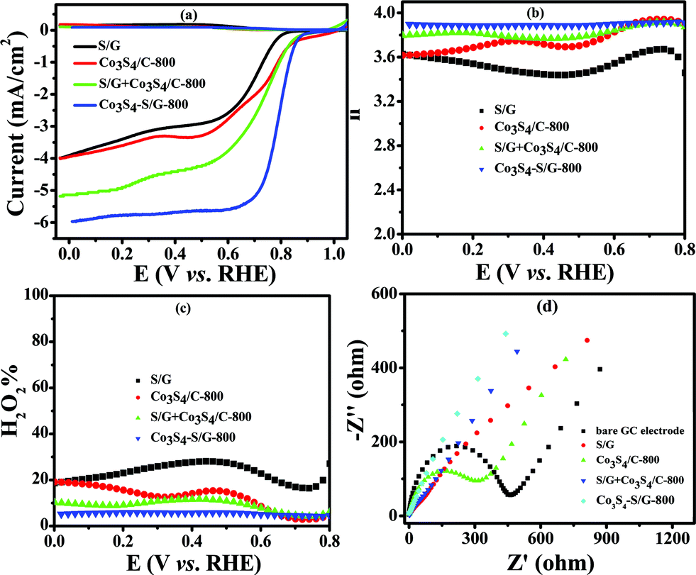 | ||
| Fig. 5 LSV curves (a) electron transfer number (b) and H2O2 yield (c) of S/G, Co3S4/C-800, S/G + Co3S4/C-800 (physical mixture) and Co3S4–S/G-800 catalysts in an O2-saturated 0.1 M KOH electrolyte with a scan rate of 5 mV s−1. EIS (d) of S/G, Co3S4/C-800, S/G + Co3S4/C-800 and Co3S4–S/G-800 modified working electrode in a solution of 5.0 mM Fe(CN)63−/4− containing 100 mM KCl. | ||
Moreover, Co3S4–S/G-800 also displayed excellent electrocatalytic activity in acidic solution. As shown in Fig. S11b,† the Co3S4–S/G-800 catalyst exhibited an onset potential of 0.80 V in 0.5 M H2SO4 electrolyte. Most important, the electron transfer number of the Co3S4–S/G-800 was calculated as close to four electrons (Fig. S11c†) in 0.5 M H2SO4 and the H2O2 yield is very low under the investigated potential (Fig. S11d†). Hence, the low H2O2 yield and high electrode transfer number in both alkaline and acidic conditions clearly indicate that Co3S4–S/G-800 possesses remarkable ORR catalytic efficiency. As far as we know, few reports on cobalt sulfide nanoparticles based electrocatalysts have shown higher ORR performance compared with the Co3S4–S/G-800 in both alkaline and acidic conditions (Table S4†).
For commercialization, the durability and tolerance toward methanol is another important aspect for a fuel cell. As shown in Fig. S12 and 13,† almost no change of the LSV or CV curves was observed for Co3S4–S/G-800 both in alkaline and acidic conditions, indicating little effect of methanol on the catalyst. In contrast, an obvious change of the onset potential, half-wave potential and the ORR peak can be found for the Pt/C catalyst. These phenomena reveal that the Co3S4–S/G-800 catalyst was superior to the commercial Pt/C for methanol fuel cells. Since poor tolerance is a major obstacle of non-noble metal catalysts for fuel cells, especially in harsh acidic conditions,36 it is essential to measure the stability of ORR catalysts. Herein, amperometric i–t tests were carried out to measure the stability of the Co3S4–S/G-800 with a long time of 15000 s. Impressively, as shown in Fig. 6 and S14,† after 15000 s, the Co3S4–S/G-800 exhibited a relatively slower decay than the commercial Pt/C in both alkaline and acidic conditions. Moreover, by comparing recently reported cobalt sulfide nanoparticle based electrocatalysts, such as Co1−xS/RGO hybrid,24 CoS2-based thin films25 and CoS2/N, S-GO,26 the Co3S4–S/G-800 also showed a higher thermal stability. This result convincingly exemplifies that the Co3S4–S/G-800 catalyst has favorable stability. The fabricated Co3S4–S/G-800 catalyst with these excellent features may thus hold a promising potential for fuel cells.
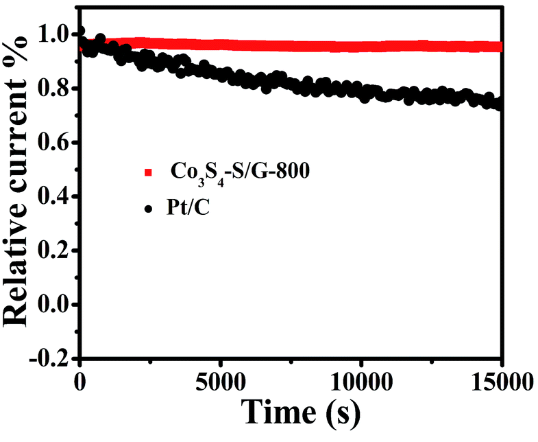 | ||
| Fig. 6 Amperometric i–t curves of Co3S4–S/G-800 and Pt/C in O2-saturated 0.1 M KOH electrolyte. | ||
Therefore, based on the characterization of the Co3S4–S/G-800 catalyst, the displayed prominent ORR activity could be attributed to these effects, (1) the high electric conduction of the support matrix; (2) the S-doped catalyst provides more favorable strains and defects for ORR; (3) the mesoporous structure in the Co3S4–S/G-800 exerts good transport ability for ORR relevant substances (O2, H+/OH−, H2O) and provides more exposed active sites; (4) a synergistic effect between the S-doped graphene and Co3S4 nanoparticles.
Conclusions
In summary, we successfully prepared a metal–S4 complex to replace traditional high-price N4-chelate macrocycles. From this a high-efficiency noble-metal-free catalyst Co3S4–S/G-800 was synthesized on a large scale by a simple and facile annealing of the inexpensive precursor and GO at 800 °C. The as-prepared Co3S4–S/G-800 catalyst showed excellent ORR catalytic activity which was comparable with commercial Pt/C. Moreover, as a noble metal-free catalyst, the Co3S4–S/G-800 manifested obviously low methanol crossover effects, and robust stability in a long time test experiment. All these results demonstrate that the S4-chelate complex can serve as an effective precursor for designing the ORR catalyst, which opens up a new strategy to achieve highly efficient, stable, and low-cost ORR catalysts. Moreover, based on this work, an easy, economical and practical method to fabricate cobalt chalcogenides also was provided by using the pure S4-chelate complex as an efficient precursor.Experimental
Chemicals and reagents
Graphite powder (spectral pure) was from Alfa Aesar (Ward Hill, MA, USA). Absolute ethanol, methanol, sulfuric acid (H2SO4) and potassium hydroxide (KOH) were purchased from Beijing Chemical Reagent (Beijing, China). 1,2-Benzenedithiol (TCI) and 20% E-TEK Pt/C were obtained from Alfar Aesar (Tianjin, China) and Millipore Mill-Q (18.2 MΩ cm) deionized water was used to prepare the aqueous solutions.Apparatus
Transmission electron microscopy (TEM) images, high angle annular dark field-scanning transmission electron microscopy (HAADF-STEM) and elemental mapping images were recorded by a TECNAI G2 high-resolution transmission electron microscope (Hitachi, Tokyo, Japan) with an accelerating voltage of 200 kV. Energy dispersive X-ray (EDX) spectra and scanning electron microscope (SEM) images were measured with an XL30 ESEM FEG SEM (Philips, Netherlands) operating with an accelerating voltage of 20 kV. X-Ray photoelectron spectroscopy (XPS) analysis was obtained from an ESCALAB-MKII X-ray photoelectron spectroscope (VG Scientific, UK). Powder X-ray diffraction (XRD) was recorded by a D8 ADVANCE (Germany) using Cu-Kα radiation (λ = 1.5406 Å). Raman spectra were recorded by a Renishaw 2000 model confocal microscopy Raman spectrometer (Renishaw Ltd., Gloucestershire, UK). Electrochemical impedance spectroscopy (EIS) was measured with an Autolab/PG30 electrochemical analyzer system (ECO Chemie B.V. Netherlands).In addition, cyclic voltammetric (CV) and amperometric i–t curves were carried out with a CH Instruments 800 voltammetric analyzer (Shanghai, China). Rotating ring-disk electrode (RRDE) and rotating disk electrode (RDE) measurements were made using a Model RRDE-3A Apparatus (ALS, Japan) coupled with a CH Instruments 800 electrochemical workstation. In the electrochemical experiments, the modified glassy carbon electrode with catalyst samples acted as the working electrode, with an Ag/AgCl (saturated KCl) electrode and a platinum wire as the reference electrode and counter electrode, respectively. All electrode potentials were referenced to the reversible hydrogen electrode (RHE) using the formula E (vs. RHE) = E (vs. Ag/AgCl) + 0.197 + 0.059pH. In 0.1 M KOH solution (pH = 13), E (vs. RHE) = E (vs. Ag/AgCl) + 0.964, while, in 0.5 M H2SO4 electrolyte (pH = 0.25), E (vs. RHE) = E (vs. Ag/AgCl) + 0.212.
Preparation of the catalyst samples
As illustrated in Fig. S1,† the S4-chelate complex of cobalt dithiolene was obtained by a previously reported method in a one-step process,37 and the UV-Vis absorption spectrum (Fig. S2†) was used to characterize the compound. Then, in a typical synthesis of Co3S4–S/G-800 samples, 2 g cobalt dithiolene was dissolved into 100 mL absolute ethanol containing 2 mg mL−1 GO (which was obtained by a modified Hummers' procedure38) with ultrasonication and stirring until a homogeneous solution was obtained. Afterwards, the solvent was removed under reduced pressure, and the remaining powder was thermally annealed under flowing Ar at 180 and 800 °C for 1 and 2 h, respectively, with a heating rate of 5 °C min−1. After that, the obtained black products were etched in 50 mL of 0.5 M H2SO4 solution for 24 h to remove unstable and inactive substance and then were washed three times with deionized water. The Co3S4–S/G-800 catalyst was obtained by drying the black product at 60 °C in a vacuum.The comparative samples of pristine graphene, sulfur-doped graphene (S/G, pyrolysis of 1,2-benzenedithiol and GO at 800 °C), Co3S4/C-800 (pyrolysis of cobalt dithiolene complex without GO), S/G + Co3S4/C-800 (physical mixture) and the nanocatalysts which were carbonized at 600, 700 and 900 °C (designated as Co3S4–S/G-600, Co3S4–S/G-700 and Co3S4–S/G-900, respectively) were also prepared to better understand the catalytic properties for ORR.
Electrocatalytic activity measurements
Prior to each experiment, the working electrode was polished with 0.3 and 0.05 μm alumina slurries and cleaned with deionized water and absolute ethanol to obtain a mirror finish. The catalyst ink was prepared as follows: 4 mg catalyst sample was added into 1 mL of a mixed solution which contained 20:1:0.075 (v/v/v) of water, absolute ethanol and Nafion (5.0 wt%). Then the solution was sonicated for 30 min to obtain 4 mg mL−1 catalyst. Before the experiments of CVs and amperometric i–t, 6 μL catalyst ink was dropped onto a glassy carbon electrode (GCE: 3.0 mm in diameter) with a loading amount of 0.34 mg cm−2 and dried under an infrared lamp. The linear sweep voltammetry (LSV) measurements were recorded by using RRDE or RDE techniques to evaluate the electrocatalytic activity of different catalyst samples. In addition, the 20% E-TEK Pt/C catalyst was also prepared in the same way and dropped with a loading amount of 25 μg Pt cm−2 as a comparison.
Before each experiment, the electrolyte was bubbled by purging high-purity N2 gas for at least 30 min in order to remove dissolved oxygen. The modified working electrode was electrochemically treated and cleaned by CV sweeping (potential scan from 1.1 to 0 V (vs. RHE)) with a scan rate of 100 mV s−1 in an N2-saturated electrolyte until a reproducible curve was achieved. Meanwhile, CV curves in N2-saturated or O2-saturated solution were obtained by CV sweeping with a scan rate of 50 mV s−1 after purging N2 or O2 at least for 30 min. The amperometric i–t curves were obtained by sweeping the Co3S4–S/G-800 or 20% E-TEK Pt/C (Pt/C) catalyst modified electrode over 15000 s at a potential of 0.614 V (vs. RHE) in O2-saturated 0.1 M KOH and 0.5 M H2SO4 solution.
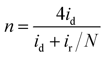
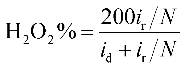
Furthermore, in the RRDE experiments, the Pt ring potential was set at 1.264 V (vs. RHE) in 0.1 M KOH and 1.012 V (vs. RHE) in 0.5 M H2SO4. The transferred electron number (n) and the generated H2O2 can be calculated from the values of id (the current of disk electrode) and ir (the current of ring current) using the following equations:39
 | (1) |
 | (2) |
The RDE measurements were performed in O2-saturated 0.1 M KOH or 0.5 M H2SO4 electrolyte by a negative-direction sweeping potential with a scan rate of 5 mV s−1 under different electrode rotation rates. The electron transfer also can be estimated according to the Koutecky–Levich equations:
 | (3) |
| B = 0.2nF(D0)2/3v−1/6C0 | (4) |
485 C mol−1, and D0 is the diffusion coefficient of O2 (1.9 × 10⁻⁵ cm2 s−1 in 0.1 M KOH and 1.4 × 10⁻⁵ cm2 s−1 in 0.5 M H2SO4), v represents the kinematic viscosity of the electrolyte (0.01 cm2 s−1 both in 0.1 M KOH and 0.5 M H2SO4), C0 is the bulk concentration of O2 (1.2 × 10⁻⁶ mol cm−3 in 0.1 M KOH and 1.1 × 10⁻⁶ mol cm−3 in 0.5 M H2SO4).40,41
Acknowledgements
This work was supported by National Natural Science Foundation of China with grant No. 21427811.Notes and references
- Y. Nie, L. Li and Z. D. Wei, Chem. Soc. Rev., 2015, 44, 2168 RSC.
- H. A. Gasteiger and N. M. Marković, Science, 2009, 324, 48 CrossRef CAS PubMed.
- J. B. Wu, A. Gross and H. Yang, Nano Lett., 2011, 11, 798 CrossRef CAS PubMed.
- V. R. Stamenkovic, B. Fowler, B. S. Mun, G. F. Wang and N. M. Markovic, Science, 2007, 315, 493 CrossRef CAS PubMed.
- C. L. Zhang, W. Sandorf and Z. M. Peng, ACS Catal., 2015, 5, 2296 CrossRef CAS.
- D. S. Su and G. Sun, Angew. Chem., Int. Ed., 2011, 50, 11570 CrossRef CAS PubMed.
- D. Deng, X. Pan, L. Yu, Y. Cui, Y. Jiang, J. Qi, W. X. Li, Q. Fu, X. Ma, Q. Xue, G. Sun and X. Bao, Chem. Mater., 2011, 23, 1188 CrossRef CAS.
- G. Wu, K. L. More, C. M. Johnston and P. Zelenay, Science, 2011, 332, 443 CrossRef CAS PubMed.
- Y. Liang, Y. Li, H. Wang, J. Zhou, J. Wang, T. Regier and H. Dai, Nat. Mater., 2011, 10, 780 CrossRef CAS PubMed.
- H. Wang, Y. Liang, Y. Li and H. Dai, Angew. Chem., Int. Ed., 2011, 50, 10969 CrossRef CAS PubMed.
- R. Jasinski, Nature, 1964, 201, 1212 CrossRef CAS.
- Y. Y. Jiang, Y. Z. Lu, X. Y. Lu, D. X. Han, Q. X. Zhang, L. Niu and W. Chen, ACS Catal., 2013, 3, 1263 CrossRef CAS.
- R. L. Liu, C. Malotki, L. Arnold, N. Koshino, H. Higashimura, M. Baumgarten and K. Müllen, J. Am. Chem. Soc., 2011, 133, 10372 CrossRef CAS PubMed.
- Y. Y. Jiang, Y. Z. Lu, X. D. Wang, Y. Bao, W. Chen and L. Niu, Nanoscale, 2014, 6, 15066 RSC.
- W. M. Li, A. P. Yu, D. Higgins, B. Llanos and Z. W. Chen, J. Am. Chem. Soc., 2010, 132, 17056 CrossRef CAS PubMed.
- I. Hijazi, T. Bourgeteau, R. Cornut, A. Morozan, A. Filoramo, J. Leroy, V. Derycke, B. Jousselme and S. Campidelli, J. Am. Chem. Soc., 2014, 136, 6348 CrossRef CAS PubMed.
- P. J. Wei, G. Q. Yu, Y. Naruta and J. G. Liu, Angew. Chem., Int. Ed., 2014, 53, 6659 CrossRef CAS PubMed.
- Y. S. Zhu, B. S. Zhang, X. Liu, D. W. Wang and D. S. Su, Angew. Chem., Int. Ed., 2014, 53, 10673 CrossRef CAS PubMed.
- I. Hijazi, T. Bourgeteau, R. Cornut, A. Morozan, A. Filoramo, J. Leroy, V. Derycke, B. Jousselme and S. Campidelli, J. Am. Chem. Soc., 2014, 136, 6348 CrossRef CAS PubMed.
- H. Choi, N. Kumar and J. Baek, Nanoscale, 2015, 7, 6991 RSC.
- M. X. Shen, C. P. Ruan, Y. Chen, C. H. Jiang, K. L. Ai and L. H. Lu, ACS Appl. Mater. Interfaces, 2015, 7, 1207 CAS.
- N. Mahmood, C. Z. Zhang, J. Jiang, F. Liu and Y. L. Hou, Chem.–Eur. J., 2013, 19, 5183 CrossRef CAS PubMed.
- R. A. Sidik and A. B. Anderson, J. Phys. Chem. B, 2006, 110, 936 CrossRef CAS PubMed.
- H. L. Wang, Y. Y. Liang, Y. G. Li and H. J. Dai, Angew. Chem., Int. Ed., 2011, 50, 10969 CrossRef CAS PubMed.
- L. Zhu, D. Susac, M. Teo, K. C. Wong, P. C. Wong, R. R. Parsons, D. Bizzotto, K. R. Mitchell and S. A. Campbell, J. Catal., 2008, 258, 235 CrossRef CAS.
- T. Sun, Q. Wu, R. C. Che, Y. F. Bu, Y. F. Jiang, Y. Li, L. J. Yang, X. Z. Wang and Z. Hu, ACS Catal., 2015, 5, 3625 CrossRef.
- K. P. Singh, E. J. Bae and J. S. Yu, J. Am. Chem. Soc., 2015, 137, 3165 CrossRef CAS PubMed.
- J. Liang, Y. Zheng, J. Chen, J. Liu, D. H. Jurcakova, M. Jaroniec and S. Z. Qiao, Angew. Chem., Int. Ed., 2012, 51, 3892 CrossRef CAS PubMed.
- L. Lin, Q. Zhu and A. W. Xu, J. Am. Chem. Soc., 2014, 136, 11027 CrossRef CAS PubMed.
- S. L. Zhao, H. J. Yin, L. Du, L. C. He, K. Zhao, L. Chang, G. P. Yin, H. J. Zhao, S. Q. Liu and Z. Y. Tang, ACS Nano, 2014, 8, 12660 CrossRef CAS PubMed.
- Y. Hu, J. Q. Jensen, W. Zhang, L. N. Cleemann, W. Xing, N. J. Bjerrum and Q. Li, Angew. Chem., Int. Ed., 2014, 53, 3675 CrossRef CAS PubMed.
- Z. Y. Wu, X. X. Xu, B. C. Hu, H. W. Liang, Y. Lin, L. F. Chen and S. H. Yu, Angew. Chem., Int. Ed., 2015, 54, 8179 CrossRef CAS PubMed.
- Y. Chen, J. Li, T. Mei, X. G. Hu, D. W. Liu, J. C. Wang, M. Hao, J. H. Li, J. Y. Wang and X. B. Wang, J. Mater. Chem. A, 2014, 2, 20714 CAS.
- L. Zhu, D. Susac, M. Teo and K. Wong, J. Catal., 2008, 258, 235 CrossRef CAS.
- H. T. Liu, Y. Q. Liu and D. B. Zhu, J. Mater. Chem., 2011, 21, 3335 RSC.
- W. X. Yang, Y. Q. Zhang, C. Y. Liu and J. B. Jia, J. Power Sources, 2015, 274, 595 CrossRef CAS.
- W. McNamara, Z. J. Han, P. Alperin, W. Brennessel, P. Holland and R. Eisenberg, J. Am. Chem. Soc., 2011, 133, 15368 CrossRef CAS PubMed.
- W. S. Hummers and R. E. Offeman, J. Am. Chem. Soc., 1958, 80, 1339 CrossRef CAS.
- G. Ma, R. Jia, J. Zhao, Z. Wang, C. Song, S. Jia and Z. Zhu, J. Phys. Chem. C, 2011, 115, 25148 CAS.
- R. Z. Zhang, S. J. He, Y. Z. Lu and W. Chen, J. Mater. Chem. A, 2015, 3, 3559 CAS.
- M. Jahan, Z. L. Liu and K. Loh, Adv. Funct. Mater., 2013, 23, 5363 CrossRef CAS.
Footnote |
| † Electronic supplementary information (ESI) available: Additional information: SEM image, EDX spectra, XPS survey spectra and supporting CVs, LSV analysis. See DOI: 10.1039/c6sc00357e |
| This journal is © The Royal Society of Chemistry 2016 |