
 Open Access Article
 This Open Access Article is licensed under a Creative Commons Attribution-Non Commercial 3.0 Unported Licence
Ruthenium(II)-polypyridyl zirconium(IV) metal–organic frameworks as a new class of sensitized solar cells†
W. A.
Maza
 ,
A. J.
Haring
,
S. R.
Ahrenholtz
,
C. C.
Epley
,
S. Y.
Lin
and
A. J.
Morris
*
,
A. J.
Haring
,
S. R.
Ahrenholtz
,
C. C.
Epley
,
S. Y.
Lin
and
A. J.
Morris
*
Department of Chemistry, Virginia Tech, Blacksburg, VA 24061, USA. E-mail: ajmorris@vt.edu
First published on 16th October 2015
Abstract
A series of Ru(II)L2L′ (L = 2,2′-bipyridyl, L′ = 2,2′-bipyridine-5,5′-dicarboxylic acid), RuDCBPY, -containing zirconium(IV) coordination polymer thin films have been prepared as sensitizing materials for solar cell applications. These metal–organic framework (MOF) sensitized solar cells, MOFSCs, each are shown to generate photocurrent in response to simulated 1 sun illumination. Emission lifetime measurements indicate the excited state quenching of RuDCBPY at the MOF–TiO2 interface is extremely efficient (>90%), presumably due to electron injection into TiO2. A mechanism is proposed in which RuDCBPY-centers photo-excited within the MOF-bulk undergo isotropic energy migration up to 25 nm from the point of origin. This work represents the first example in which a MOFSC is directly compared to the constituent dye adsorbed on TiO2 (DSC). Importantly, the MOFSCs outperformed their RuDCBPY–TiO2 DSC counterpart under the conditions used here and, thus, are solidified as promising solar cell platforms.
Introduction
Metal–organic frameworks (MOFs) have shown considerable promise for a number of different applications including gas storage and separation, electro- and photo-catalysis, electrical and optical sensing, as well as photovoltaic applications.1–10 Incorporation of photoactive ligands into the backbone of the material or by encapsulation within the pores of the material may impart additional reactivity due to the natures of their excited states. Indeed, a number of examples have been reported so far and, more recently, reviewed.4,11–23In particular, MOFs containing photoactive ligands or guest molecules have been designed and characterized as potential materials for photovoltaic applications.24–32 This includes their use as scaffolds or hosts for commercially available dyes for use as dye-sensitized solar cells (DSCs). The extraordinarily large surface areas afforded by MOFs offer even higher population densities of dye atop TiO2, while their spatially rigid and size restrictive pores can minimize deleterious effects due to dye aggregation. These MOF-based cells participating as dye hosts have shown power conversion efficiencies (PCEs, η) up to ∼5%.29,33 However, the materials explored in these reports are limited by effusion of the dyes from the material bulk.
Commercially available MOFs containing aromatic ligands have been explored for their photovoltaic competence.29,30,32,34,35 These include materials comprised of the benzene derivatives terephthalic acid and benzenetricarboxylic acid. Although the short-lived singlet excited states of benzene-type ligands lie well outside the visible region, some evidence suggests very fast (<10 ns) formation of a charge separated state upon UV-excitation.30 More recently, a 2D coordination polymer thin film photovoltaic device comprised of porphyrinic linkers and Zn(II)-oxo nodes has been prepared by liquid-phase epitaxy.36 However, these materials demonstrate poor PCEs – typically less than 1%.
The high efficiency of ruthenium(II) polypyridyl dyes in DSCs (PCEs of up to 12%) has instigated incorporation of similar transition metal coordination complexes into MOF sensitized solar cells (MOFSCs) by encapsulation.37–40 A variety of different MOFs have been modified with ruthenium complexes as either structural supports or via encapsulation.12,13,15,41–47 Lin and co-workers have recently synthesized a water stable zirconium(IV) biphenyldicarboxylic acid metal–organic framework in which ruthenium(II) bis-(2,2′-bipyridine)(2,2′-bipyridine-5,5′-dicarboxylic acid), RuDCBPY, was heterogeneously incorporated into the structural backbone of the framework.25 At low doping concentrations, it was found that the excited state properties of the RuDCBPY-doped UiO-67 material resembled that of RuDCBPY in DMF displaying a long-lived (∼1.4 μs) triplet metal-to-ligand charge transfer, 3MLCT, state.48 Increasing the doping concentration of RuDCBPY in the UiO-67 material was accompanied by a marked decrease in emission lifetime, which was proposed to be due to homogeneous energy transfer between RuDCBPY centers.48,49 It was also shown that this same material could be grown onto conductive fluorine-doped tin oxide (FTO) coated glass substrates without changing its excited state properties or dynamics.49 Therefore, it was postulated that these RuDCBPY-doped UiO-67 films could also be grown onto TiO2 as a sensitizing material for photovoltaic applications, which is the subject of this report.
Results and discussion
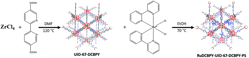
A series of zirconium(IV)-based MOFs incorporating ruthenium(II) polypyridyl dyes as ligands, forming the backbone of the material, were explored here as sensitizers for photovoltaic solar cell applications. RuDCBPY–UiO-67 (Scheme 1) and RuDCBPY–UiO-67–DCBPY-X (Schemes 2 and 3) films were solvothermally grown onto TiO2-coated FTO glass as described previously.49 RuDCBPY–UiO-67–DCBPY-X was prepared by two methods: incubation of ZrCl4, DCBPY, and Ru(bpy)2Cl2 in DMF and heating at 120 °C for 24 hours to yield RuDCBPY–UiO-67–DCBPY-OP (OP = one pot, Scheme 2), and by post-synthetic modification of a UiO-67–DCBPY film by incubation in an ethanolic solution of Ru(bpy)2Cl2 to yield RuDCBPY–UiO-67–DCBPY-PS (PS = post synthetic, Scheme 3). The coordination of Ru(bpy)2 to the UiO-67–DCBPY was confirmed by diffuse reflectance UV-vis spectroscopy (ESI Fig. S10 and S11†).50 Presumably, the UiO-67–DCBPY film is stable enough for the RuDCBPY to be prepared in situ without perturbation of the morphology of the material. Powder X-ray diffraction patterns (PXRD) of the post-synthetically modified material support this assumption (see Fig. S1 in the ESI†). Lastly, a new Zr(IV)-coordination polymer has also been synthesized and films of the material grown on TiO2-coated FTO, RuDCBPY–ZrMOF–TiO2 (see ESI† for characterization). The PXRD pattern of the RuDCBPY–ZrMOF powder, though indicative of a crystalline material, was considerably different than that of UiO-67, UiO-67–DCBPY, RuDCBPY–UiO-67, and RuDCBPY–UiO-67–DCBPY (Fig. S1 in ESI†). Additional structural characterization (SEM and PXRD) and the photophysical characteristics of these materials (as well as a number of control materials) are summarized in Table 1 and the ESI.†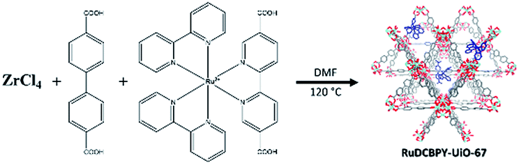 | ||
| Scheme 1 RuDCBPY–UiO-67. | ||
 | ||
| Scheme 2 RuDCBPY–UiO-67–DCBPY-OP. | ||
 | ||
| Scheme 3 RuDCBPY–UiO-67–DCBPY-PS. | ||
| Material (dopant density) | Emission lifetime | E 1MLCT (eV) | E 3MLCT (eV) | ||
|---|---|---|---|---|---|
| τ′′obs (ns) | τ′obs (ns) | ||||
| a Errors associated with all values obtained here are ±5% based on three trials. b In DMF according to ref. 48. c ref. 49. OP = one pot synthetic method, PS = post-synthetic method. d E 1MLCT was approximated as the intersection of the diffuse reflectance and emission spectra and E3MLCT was approximated as the maxima of the emission spectra. | |||||
| RuDBCPY | DMF | — | 880b | 462 nmb (2.69 eV) | 645 nmb (1.92 eV) |
| TiO2 | 25 | 474 | 430 nm (2.89 eV) | 552 nm (2.25 eV) | |
| RuBPY@UiO-67 | TiO2 | 23 | 412 | 442 nm (2.81 eV) | 605 nm (2.05 eV) |
| RuDCBPY–UiO-67 (∼20 mm) | TiO2 | 35 | 388 | 430 nm (2.89 eV) | 636 nm (1.95 eV) |
| FTO | — | 327c | 449 nmc (2.76 eV) | 634 nmc (1.96 eV) | |
| RuDCBPY–UiO-67–DCBPY-OP (∼25 mm) | TiO2 | 4 | 221 | 437 nm (2.84 eV) | 628 nm (1.98 eV) |
| FTO | — | 234 | 435 nm (2.85 eV) | 639 nm (1.94 eV) | |
| RuDCBPY–UiO-67–DCBPY-PS (∼30 mm) | TiO2 | 13 | 143 | 439 nm (2.83 eV) | 640 nm (1.94 eV) |
| FTO | — | 133 | 437 nm (2.84 eV) | 654 nm (1.90 eV) | |
| RuDCBPY–ZrMOF | TiO2 | 2 | 204 | 437 nm (2.84 eV) | 645 nm (1.92 eV) |
| FTO | 16 | 202 | 440 nm (2.82 eV) | 659 nm (1.88 eV) | |
In an earlier report, the photophysics of RuDCBPY–UiO-67 thin films grown on FTO were shown to behave similar to RuDCBPY–UiO-67 powders.49 That is, the long lifetime of the emissive 3MLCT state corresponding to RuDCBPY centres incorporated into the backbone of the MOF was found to be sensitive to the degree of RuDCBPY doping within the material. It was purported that this observed increase in the 3MLCT decay rate was due to a homogeneous resonance energy transfer reaction between RuDCBPY centres leading to excited state energy migration throughout the material.48,49 The observed RuDCBPY–RuDCBPY distance dependence on the rate of energy transfer was thought to lie between the Förster and Perrin regimes of donor–acceptor coulombic coupling (vida infra).48
Given this, and assuming that the energetics related to the Ru3+/2+ ground state oxidation of RuDCBPY (E1/2(Ru3+/2+) = 1.50 V, vs. NHE)51 incorporated in the material is not significantly perturbed relative to RuDCBPY in solution, then these materials present promising sensitizers for photovoltaic applications. The expectation of the invariability of the energetics of RuDCBPY incorporated into the UiO-67 and UiO-67–DCBPY MOFs is based on electrochemical properties of Ru(bpy)32+ encapsulated in zeolite-Y and electrochemical observations of small molecules incorporated into MOFs.52–56 Indeed, encapsulation of Ru(bpy)32+ by zeolite-Y resulted in negligible perturbation of the Ru3+/2+ couple.52 The Ru3+/2+E1/2 observed in zeolite-Y occurred at ∼1.5 V (vs. NHE, compared to 1.58 V for the same compound in a LiBF4/CH3CN electrolyte solution).52 Additionally, it has recently been demonstrated that the electrochemical properties of a series of pyrene-based MOF thin films, NU-901 and NU-1000, on FTO do not significantly differ from that observed for the ligand in solution – demonstrating an E1/2 ∼ 1.6 V (vs. NHE) for the reversible pyrene oxidation couple in the MOF compared to E1/2 ∼ 1.54 V (vs. NHE) in solution.54,56,57
A moderate photocurrent response was observed for all of the frameworks tested upon front-side illumination of MOF-sensitized TiO2 cells constructed with a tetrabutylammonium iodide (TBAI) and iodine based electrolyte in CH3CN and platinum counter electrode (Fig. 1, 2 and 4). Short circuit current densities (JSC) and open circuit potentials (VOC) were found to range between ∼−0.03 mA cm−2 to ∼−0.54 mA cm−2 and ∼−370 mV to ∼−520 mV, respectively, leading to maximum observed power conversion efficiencies, η, of 0.125% (Table 2). All of the materials tested showed a significant amount of charge recombination (FFavg = 0.50); presumably, due to recombination between electrons in the conduction band of TiO2 and oxidized redox mediator, I3−, which may be due to partial occlusion of the pores to I− and/or I3− diffusion by RuDCBPY. The poor PCEs (η < 1%) observed in the electrolyte used here (0.5 M TBAI, 0.05 M I2 in CH3CN) are not surprising when considering the well-known cation effect on the energetics and kinetics of electron injection into TiO2.58–61 Indeed, TBA+ has been implicated in deterring electron injection into TiO2 relative to other cations.62 This is purportedly due to a shift in the TiO2 energetics possible through the intercalation of small cations such as Li+, H+, or Na+ into TiO2 that is not possible with the larger TBA+ cation.58,63
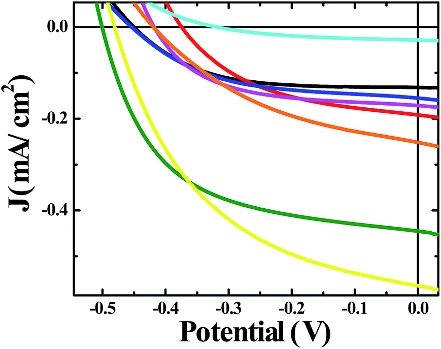 | ||
| Fig. 1 J–V curves of solar cells constructed with bare unmodified TiO2 (black), RuDCBPY on TiO2 (red), undoped UiO-67–TiO2 (blue), RuBPY@UiO-67–TiO2 (pink), RuDCBPY–UiO-67–TiO2 (green), RuDCBPY–UiO-67–DCBPY-OP–TiO2 (orange), RuDCBPY–UiO-67–DCBPY-PS–TiO2 (cyan), and RuDCBPY–ZrMOF–TiO2 (yellow) in a tetrabutylammonium iodide (TBAI) and iodine based electrolyte in CH3CN and platinum counter electrode. | ||
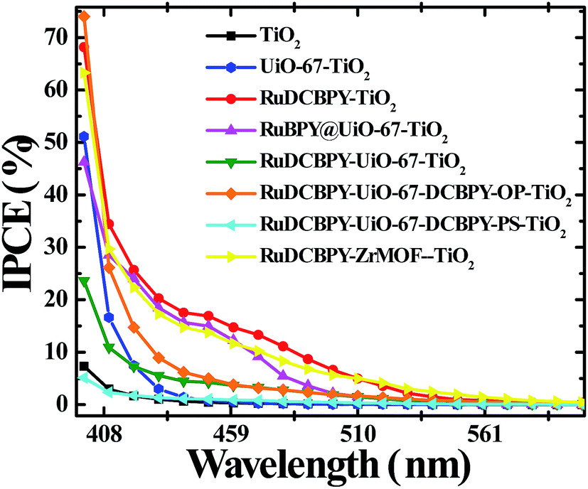 | ||
| Fig. 2 Incident photon to current conversion efficiency (IPCE) spectra of unmodified TiO2 (black), RuDCBPY on TiO2 (red), undoped UiO-67–TiO2 (blue), RuBPY@UiO-67–TiO2 (pink), RuDCBPY–UiO-67–TiO2 (green), RuDCBPY–UiO-67–DCBPY-OP–TiO2 (orange), RuDCBPY–UiO-67–DCBPY-PS–TiO2 (cyan), and RuDCBPY–ZrMOF–TiO2 (yellow) collected in a tetrabutylammonium iodide (TBAI) and iodine based electrolyte in CH3CN with a platinum counter electrode. | ||
| J SC (mA cm−2) | V OC (V) | FF | η (%) | |
|---|---|---|---|---|
| a Average values and errors shown are based on at least 3 trials. | ||||
| TiO2 | −0.132 ± 0.001 | −0.451 ± 0.010 | 0.57 ± 0.05 | 0.034 ± 0.011 |
| RuDCBPY–TiO2 | −0.203 ± 0.051 | −0.364 ± 0.047 | 0.46 ± 0.01 | 0.077 ± 0.010 |
| UiO-67–DCBPY–TiO2 | −0.180 ± 0.003 | −0.471 ± 0.036 | 0.59 ± 0.03 | 0.049 ± 0.005 |
| RuBPY@UiO-67–TiO2 | −0.175 ± 0.068 | −0.455 ± 0.072 | 0.57 ± 0.06 | 0.045 ± 0.015 |
| RuDCBPY–UiO-67–TiO2 | −0.446 ± 0.097 | −0.480 ± 0.019 | 0.55 ± 0.04 | 0.123 ± 0.021 |
| RuDCBPY–UiO-67–DCBPY-OP–TiO2 | −0.251 ± 0.025 | −0.420 ± 0.026 | 0.44 ± 0.06 | 0.046 ± 0.005 |
| RuDCBPY–UiO-67–DCBPY-PS–TiO2 | −0.028 ± 0.005 | −0.324 ± 0.035 | 0.41 ± 0.05 | 0.004 ± 0.001 |
| RuDCBPY–ZrMOF–TiO2 | −0.564 ± 0.129 | −0.482 ± 0.035 | 0.47 ± 0.04 | 0.125 ± 0.038 |
RuDCBPY–UiO-67–TiO2 and RuDCBPY–ZrMOF–TiO2 out-performed (higher JSC, VOC and η) the other constructs tested, including RuDCBPY simply adsorbed on the surface of unmodified TiO2 and Ru(bpy)3Cl2 diffused into undoped UiO-67 grown on TiO2. Additionally, RuDCBPY–UiO-67–DCBPY-PS–TiO2 performed comparatively worse than the unmodified TiO2 control. This is evidence that synthetic procedure has a direct impact on observed photophysical properties. Since all of the MOFs tested contain RuDCBPY light-active centres, the source of varied solar cell performance is most likely not molecular in origin but rather due to the 3D orientation and localization of these centres within the MOFs. Below, we will discuss such structure dependent effects in the context of the photophysical processes involved in the explored MOFSCs.
The MOFSCs reported here differ significantly from conventional DSC in that the sensitizing “dyes” are expected to be spatially distributed on the TiO2 surface and above the TiO2 throughout the backbone of the MOF crystalline matrix (Fig. 3). In this geometry, there are at least three processes accounting for the observed photocurrent and excited state quenching dynamics upon illumination of the MOF (summarized in Fig. 4): (1) excitation of the UiO-67 or UiO-67–DCBPY followed by charge separation and electron injection into TiO2, (2) excitation of RuDCBPY ligands within the energy diffusion distance that through energy hopping/migration and/or direct interactions results in electron injection into TiO2, and (3) energy hopping/migration between RuDCBPY centres within the bulk of the MOF beyond the energy hopping diffusion length from the MOF–TiO2 interface.
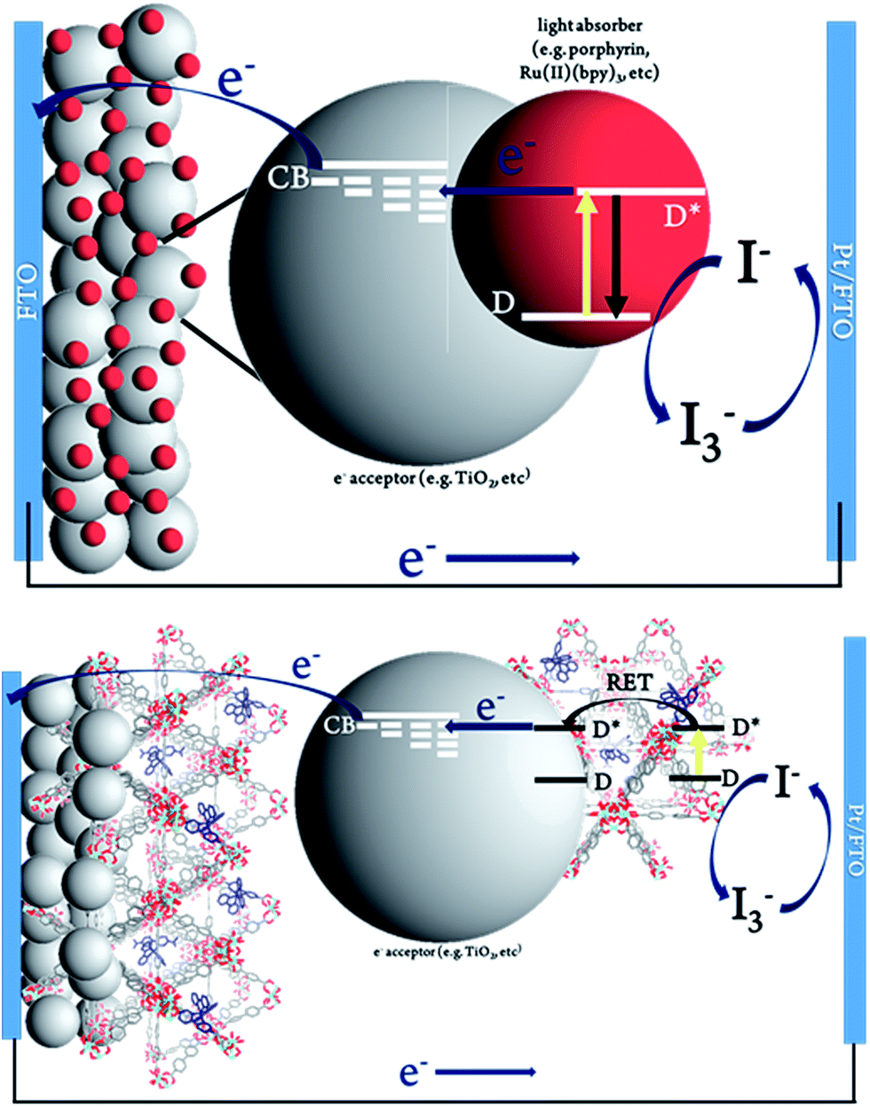 | ||
| Fig. 3 Schematic representation of (top) conventional dye-sensitized solar cell and (bottom) Ru-MOF sensitized solar cells, MOFSCs. | ||
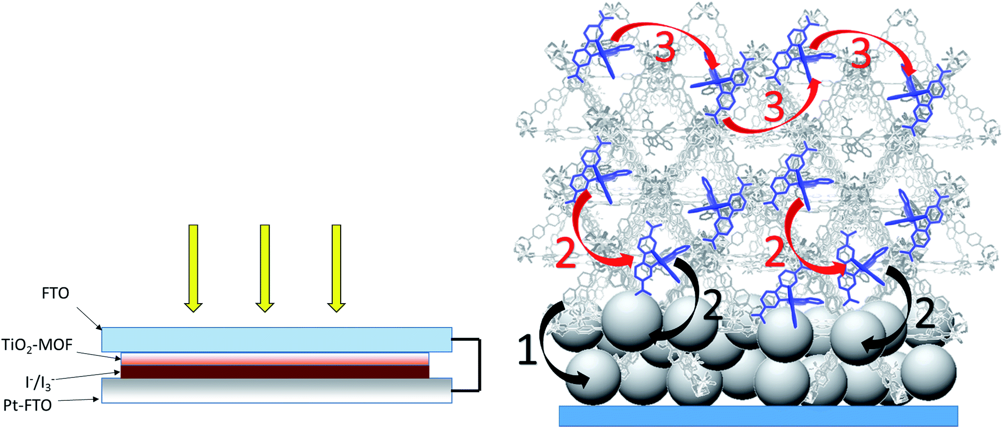 | ||
| Fig. 4 (Left) Front-side solar cell sandwich arrangement used for the photovoltaic cells prepared here. (Right) General scheme depicting the potential processes contributing to the observed photocurrent for the RuDCBPY-MOF modified TiO2 films. The black arrows indicate charge separation steps whereas the red arrows are indicative of energy transfer/hopping between RuDCBPY centers within the MOF. (1) Charge separation between the BPDC or DCBPY MOF ligands and TiO2. (2) Charge separation between RuDCBPY centers at or within the energy hopping diffusion length from the MOF/TiO2 interface and the TiO2. (3) Non-directional energy transfer/hopping between RuDCBPY centers within the MOF. | ||
(1) Charge separation between the UiO-67 MOF backbone and TiO2
It is possible that illumination of undoped UiO-67 with broadband light results in BPDC-localized reactive singlet and/or triplet excited state(s) which undergo charge separation at the MOF/TiO2 interface. This is energetically plausible considering the energy gap between the highest occupied molecular orbitals (HOMOs) and lowest unoccupied molecular orbitals (LUMOs) of UiO-67 at ∼3.6 eV (∼340 nm absorption band edge) reported previously for UiO-67, which agrees well with our observations (not shown).64 Computational evidence suggest the LUMOs of the UiO-type frameworks are largely comprised of Zr d-states whereas the ligand H s-, C s-, and O p-states contribute to the HOMOs.65 In addition, transient diffuse reflectance measurements performed on the UiO-66 MOF, a benzene-1,4-dicarboxylate (BDC) analogue of UiO-67, indicate that the transients observed upon 355 nm excitation are sensitive to O2, a known quencher of triplet states.66 This is suggestive of formation of a BDC-localized triplet, which presents a broad and diffuse transient spectra between 350 nm and 800 nm.35 Charge separation between the UiO-67 backbone and TiO2 is further supported here by the observation of modest photocurrent upon one sun illumination of undoped UiO-67 grown on TiO2 in addition to the slightly improved performance over unmodified TiO2 (Table 2, Fig. 1 and 2). As evident from the results shown in Table 2, the contribution of the UiO-67 to the total photocurrent is minimal. Therefore, the dynamics of electron injection into TiO2 by the UiO-67 was not explored further.(2) Charge separation between RuDCBPY at or within the energy hopping distance from the MOF–TiO2 interface and TiO2
Upon excitation, the observed emission lifetime decays of the Ru-MOF/TiO2 photoanodes probed here displayed non-exponential kinetics. The decays were best fit to a bi-exponential decay model and the results are summarized in Table 1. The bi-exponential fits indicate the presence of a slow 100–300 ns phase and a fast 4 ns to 30 ns phase. The magnitude of the slow lifetime component of the decays are consistent with the magnitude of the exponential lifetime decays in the absence of TiO2. Time-resolved emission decays of Ru(bpy)2(4,4′-DCBPY), 4,4′-DBCPY = 2,2′-bipyridyl-4,4′-dicarboxylic acid, on TiO2 often display complex kinetics with lifetimes in the range of 1 ns to 2 μs.67,68 By analogy to these reports and the results obtained here, the fast component of the emission decays (τ′′obs) is ascribed to the quenching of the of RuDCBPY excited states at or within the energy hopping distance (Rhop) from the MOF–TiO2 interface by electron injection from RuDCBPY into TiO2. The long lifetime component (τ′obs), however, is attributed to homogeneous RET occurring within the MOF bulk at distances from the MOF–TiO2 junction greater than Rhop (vide infra).The slow component of the emission decay rate is comprised of the natural lifetime of RuDCBPY, in other words the sum of the radiative and non-radiative decay rate constants in the absence of intermolecular interactions (kr + knr), as well as a quenching rate constant corresponding to the rate of energy migration, khop, according to
| (τ′obs)−1 = kr + knr + khop | (1) |
The second, fast lifetime component in the emission decays, (τ′′obs)−1, should have contributions from the natural 3MLCT decay rate of RuDCBPY, kr + knr, plus contributions from resonance energy transfer and migration, khop, and an additional electron transfer/injection term, kinj.
| (τ′′obs)−1 = kr + knr + khop + kinj | (2) |
The values from eqn (2) for kinj were obtained by assuming the sum of kr, knr, and khop were approximately equal to (τ′obs)−1 and are included in Table 3.
| k hop (×106 s−1) | k inj (×107 s−1) | Φ RET | Φ inj | r (Å) | R hop (3D, Å) | R hop (2D, Å) | R hop (1D, Å) | |
|---|---|---|---|---|---|---|---|---|
| RuDCBPY–UiO-67–TiO2 | 1.86 | 2.59 | 0.72 | 0.91 | 24 | 254 | 207 | 147 |
| RuDCBPY–UiO-67–DCBPY–TiO2-OP | 3.81 | 24.5 | 0.84 | 0.98 | 19 | 177 | 145 | 102 |
| RuDCBPY–UiO-67–DCBPY–TiO2-PS | 6.28 | 6.99 | 0.89 | 0.91 | 16 | 138 | 113 | 80 |
| RuDCBPY–ZrMOF–TiO2 | 4.19 | 49.5 | 0.85 | 0.99 | 19 | 169 | 138 | 98 |
The electron injection efficiency, Φinj, at the TiO2–MOF interface is then defined as the product of τ′′obs and kinj:
| Φinj = τ′′obskinj | (3) |
The magnitudes of kinj and Φinj presented in Table 3 are indicative of strong coupling between RuDCBPY and TiO2.
(3) Energy transfer/hopping within the bulk of the MOF beyond the energy hopping diffusion length from the MOF–TiO2 interface
Illumination of RuDCBPY centres found throughout the bulk of the material result in formation of a 1MLCT excited state which quickly undergoes intersystem crossing to generate an emissive 3MLCT excited state. It has been observed that in RuDCBPY-doped UiO-67 powders and films, the emission lifetime of the 3MLCT excited state decreases dramatically as the number of RuDCBPY centres is increased within the material.48,49 It was argued that the origin of the quenching of the long lifetime component of the emission decay is homogeneous resonance energy transfer between RuDCBPY centres within the material. The aforementioned slow component of the bi-exponential emission lifetime decay is attributed to this process based on the similarities of their magnitudes with the magnitude of the lifetime obtained previously for RuDCBPY–UiO-67.48,49 From eqn (1), khop was calculated to be between 1.9 × 10⁶ s−1 and 6.3 × 10⁶ s−1 for the Ru-MOF/TiO2 photoanodes explored here (where kr + knr is taken here to be 7.14 × 10⁵ s−1 for dilute concentrations of RuDCBPY in UiO-67).The average hopping distance, Rhop, is related to khop according to eqn (4),
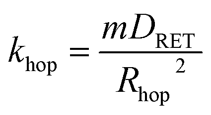 | (4) |
The average RuDCBPY intermolecular distances, r, were calculated from the value of Rhop and the energy transfer efficiency, ΦRET, according to the relationship:
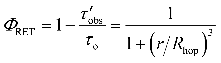 | (5) |
At low doping concentrations and large RuDCBPY intermolecular separation within the MOF, the distance dependence of the energy transfer was found to lie between the very-weak and weak coupling regime based on an Inokuti–Hirayama analysis of the lifetime decays.48,49,72 That is, the rate of RET was proposed to be proportional to an r−4 intermolecular distance dependence. The Inokuti–Hirayama equation, however, assumes that the interactions between energy donors and acceptors occur over three-dimensions.72 Recent evidence suggests that, in the case of post-synthetically doped materials, the dimensionality of energy transfer occurring between RuDCBPY centres is dependent on the doping concentration.50 For that reason, Rhop, has also been calculated for two dimensional, and one dimensional RET (Table 3). Alternatively, intermolecular energy migration according to the Dexter mechanism has been observed between ruthenium centres in a variety of MOF structures.41–45 For example, Meyer, et al. have reported a MOF consisting of Ru(II)(2,2′-bipyridyl-4,4′-dicarboxylic acid)2(2,2′-bipyridine)[PF6]2 ligands and Zn(II) carboxylate nodes displaying Ru*–Ru energy migration up to 40 Å by the Dexter mechanism.42
The results in Table 3 suggest a large degree of coupling between interacting RuDCBPY centres such that energy hopping/migration occurs over distances up to 15 nm on average. This distance is, however, considerably smaller than the average thickness of the films grown solvothermally (∼10 μm based on SEM, Fig. S7†).49 From theoretical considerations, it has been shown that the electron injection yield is expected to decrease as a function of increasing number of energy “hopping” units in multimeric light harvesting arrays.73 Therefore, the energy “harvested” at RuDCBPY-centres in the UiO-67 and UiO-67–DCBPY bulk at distances further than 15 nm from the TiO2–MOF interface is likely lost to thermalization.74
Although the differences between resonance energy transfer, electron injection efficiencies, and power conversion efficiencies for the RuDCBPY containing MOFs explored are not very large, a few observations of interest are pointed out. In terms of resonance energy transfer, it seems that the RuDCBPY-UiO-67–DCBPY-PS–TiO2 displayed the largest degree of coupling between RuDCBPY centres and interacting pairs (based on the magnitude of khop) followed by RuDCBPY–ZrMOF–TiO2, RuDCBPY–UiO-67–DCBP-OP–TiO2, and then RuDCBPY–UiO-67–TiO2. This could be due to the nature of the post-synthetic preparative method. It has been shown by confocal fluorescence microscopy that denser populations of RuDCBPY centres form along the edges and vertices of the UiO-67–DCBPY surface closest to the MOF-solution interface regardless of the degree of doping.50 It was purported that the non-uniform distribution of RuDCBPY doping in the framework by the post-synthetic method was likely due to diffusional limitations of the Ru(bpy)2Cl2 imposed by the MOF (either steric or thermodynamic in nature) inhibiting penetration of RuDCBPY into the bulk of the crystalline material. This was supported by recent evidence obtained by fluorescence microscopy depicting the loading of a IRMOF-10 MOF with Ru(bpy)2(dpbpy), dpbpy = 4,4′-diphosphonate-2,2′-bipyridine, by slow diffusion in a CH3CN solution.39
The poor PCE of the RuDCBPY–UiO-67–DCBPY-PS–TiO2 material is then a direct consequence of the nature of the post-synthetic preparative method if the formation of RuDCBPY centres throughout the UiO-67–DCBPY film saturates the outer layers near the MOF-solution interface yet only sparingly populate the MOF-bulk and, in particular, the MOF–TiO2 interface. Significant differences between the diffuse reflectance and IPCE of RuDCBPY–UiO-67–DCBPY–TiO2-PS are evident when overlain (Fig. S20†). Specifically, the differences present are indicative of reduced contribution of the RuDCBPY to the total photocurrent. These observations are attributed to thermalization of those RuDCBPY excited states generated outside of the Rhop distance away from the MOF–TiO2 interface. Similarly, the dramatically reduced JSC and VOC values relative to the other Ru-MOFSCs might be explained by occlusion of the UiO-67–DCBPY pores by RuDCBPY formation on the outer layers of the films which may obstruct diffusion of I3− into the MOF restricting regeneration of RuDCBPY after electron injection into TiO2. It should be noted that accessibility of I− to oxidized RuDCBPY sites and effusion of I3− out of the MOF may also be hindered in the RuDCBPY–UiO-67 and RuDCBPY–UiO-67-OP films. However, the presumed random distribution of the RuDCBPY ligands throughout the volume of the MOF relative to that proposed for RuDCBPY–UiO-67-PS likely increases the number of available diffusion pathways for I− and I3− in, out, and through the films relative to RuDCBPY–UiO-67-PS. These observations may point to the importance of the role of interfacial RuDCBPY at the MOF–TiO2 boundary. It is likely that “one-pot” methods of preparing the MOFSCs using the preformed dye, i.e. RuDCBPY–UiO-67 and RuDCBPY–ZrMOF, result in larger concentrations of dye at the surface as well as a more uniform distribution of dye throughout the bulk of the framework suggesting a concentration and spatial distribution effect on the efficacy of the MOFSC.
Conclusion
To summarize, a series of RuDCBPY containing zirconium(IV)-based metal–organic frameworks were grown as thin films on TiO2 as sensitizing materials for photovoltaic applications. It was found that the mechanisms of excited state energy migration and electron transfer into TiO2 seem to be similar between materials. That is, upon generation of the RuDCBPY excited state, the energy of the excited state migrates through the film via RuDCBPY interacting pairs that are separated, on average, by ∼20 Å. The values obtained for the rate of energy migration, khop, indicate that RuDCBPY centres located at the MOF–TiO2 interface are sensitized either directly upon absorption of the incident irradiation or indirectly via resonance energy transfer processes initiated up to 15 nm away from the interface. Additionally, it seems that the choice of the preparative method of photoactive MOFs has a large effect on the power conversion efficiency of the MOFSC. Although the efficiencies of the cells prepared here are less than 1%, the MOFSCs outperformed a monolayer of the same dye on the surface of TiO2 and, therefore, present a promising platform for photovoltaic applications.Experimental
The chemicals and solvents were obtained from either Sigma-Aldrich or Fisher Scientific and used as received without further purification unless otherwise noted below.(1) Synthesis of Ru(2,2′-bipyridine)2(5,5′-dicarboxy-2,2′-bipyridine)Cl2, RuDCBPY
The synthesis of RuDCBPY has been described previously and was carried out accordingly.51 Ru(bpy)2Cl2 (160 mg, Alfa Aesar, 97%) and DCBPY (100 mg, Ark Pharm, Inc, >95%) were dissolved in 20 mL of an ethanol-basic water mix (1![[thin space (1/6-em)]](https://www.rsc.org/images/entities/char_2009.gif) :1 v/v) and refluxed under N2 overnight. The solution was cooled to room temperature and the solvent removed by rotary evaporation and recrystallized from MeOH–diethyl ether.
:1 v/v) and refluxed under N2 overnight. The solution was cooled to room temperature and the solvent removed by rotary evaporation and recrystallized from MeOH–diethyl ether.
(2) Synthesis of UiO-67–DCBPY
The synthetic procedure used to prepare UiO–67-DCBPY films was similar to a previously reported procedure for UiO-67.48,49,75 In a typical synthesis, 0.13 g of ZrCl4 (98%), and 0.14 g of DCBPY (95%) were suspended in 20 mL of anhydrous DMF (>99%) and sonicated in a 6 dram vial for five minutes. A clean FTO substrate was then introduced to the mixture. The vial was then sealed and heated at 120 °C for 12 hours after which the film was cooled to room temperature, rinsed with DMF, and dried. MOF films were grown on TiO2–FTO substrates in the same manner just described.(3) Preparation of RuDCBPY–UiO-67
Films of RuDCBPY–UiO-67 were prepared solvothermally according to a previously reported method similar to what was described above for UiO-67–DCBPY.49 Briefly, 0.13 g of ZrCl4, 0.14 g of DCBPY and 0.03 g of RuDCBPY were mixed in a 6 dram vial containing 20 mL DMF and a clean FTO substrate, sealed, and heated to 120 °C for 12 hours. The films were then rinsed thoroughly with DMF and dried. MOF films were grown on TiO2–FTO substrates in the same manner just described.(4) Preparation of RuDCBPY–UiO-67–DCBPY (one pot method)
RuDCBPY–UiO-67–DCBPY-OP films were grown on FTO and TiO2–FTO by mixing 0.13 g of ZrCl4, 0.14 g DCBPY, and 0.02 g Ru(bpy)2Cl2 (Alfa Aesar, 97%) in a 6 dram vial containing 20 mL of dry DMF. The mixture was sonicated for five minutes and the FTO substrate introduced. The vial was then sealed and heated to 120 °C for 12 hours. The film was then cooled to room temperature, rinsed thoroughly with DMF and dried.(5) Preparation of RuDCBPY–UiO-67–DCBPY (post synthetic method)
Fresh UiO-67–DCBPY films were incubated in ethanolic solutions containing 0.02 g Ru(bpy)2Cl2 (Alfa Aesar, 97%) and allowed to soak for 3 days before heating at 70 °C for 3 additional days. Once cooled to room temperature, the resulting RuDCBPY–UiO-67–DCBPY films were rinsed thoroughly with DMF and deionized water.(6) Preparation of RuDCBPY–ZrMOF powders and films
RuDCBPY–ZrMOF films were prepared by mixing RuDCBPY (0.03 g) and 0.14 g ZrCl4 in a 6 dram vial containing 10 mL dry DMF, sonicating for 5 minutes and heating at 120 °C for 12 hours after introducing an FTO or TiO2–FTO substrate. Powders were similarly prepared except instead of the components being mixed in 10 mL DMF, they were mixed in 10 mL of a DMF/formic acid mixture (1:1 v/v).
(7) Preparation of DSCs
Anatase TiO2 (Ti Nanoxide, Solaronix, 15–20 nm particle size) was doctor bladed onto clean FTO glass substrates and sintered at 450 °C for thirty minutes. The TiO2 coated FTO substrates were then placed in a 6 dram vial under the same conditions described above for the MOFSC materials. The sealed vial containing the reaction mixture was heated at 120 °C for 12 hours after which the product films were then cooled, and rinsed with DMF and acetone.The MOFSC photoanode was covered with a Pt sputter coated FTO glass slide and held in place using Surlyn (Dupont, 75 micron thickness). An acetonitrile electrolyte solution was prepared containing 0.5 M tetrabutylammonium iodide and 0.05 M iodine for the MOFSC measurements.
(8) Characterization
J–V data was collected using either a Basi Epsilon or a Pine WaveNOW potentiostat. Samples were illuminated using a Newport LCS-100 Solar Simulator equipped with an AM1.5G air mass filter calibrated to 1 sun output. IPCE curves were obtained by measuring the photocurrent generated by illumination of samples using a PTI 75 W Xe arc lamp passed through an OBB 200 mm meter Czerny-turner monochromator and normalizing the observed photocurrent by the output photon density of the arc lamp.Acknowledgements
This material is based upon work supported by the U.S. Department of Energy, Office of Science, Office of Basic Energy Sciences under Award Number DE-SC0012446.Notes and references
- Z. Dou, J. Yu, Y. Cui, Y. Yang, Z. Wang, D. Yang and G. Qian, J. Am. Chem. Soc., 2014, 136, 5527–5530 CrossRef CAS PubMed.
- D. Y. Lee, C. Y. Shin, S. J. Yoon, H. Y. Lee, W. Lee, N. K. Shrestha, J. K. Lee and S.-H. Han, Sci. Rep., 2014, 4, 3930 Search PubMed.
- H. Li, M. Eddaoudi, T. L. Groy and O. M. Yaghi, J. Am. Chem. Soc., 1998, 120, 8571–8572 CrossRef CAS.
- J.-L. Wang, C. Wang and W. Lin, ACS Catal., 2012, 2, 2630–2640 CrossRef CAS.
- M. Pramanik, A. K. Patra and A. Bhaumik, Dalton Trans., 2013, 42, 5140–5149 RSC.
- C. G. Silva, A. Corma and H. Garcia, J. Mater. Chem., 2010, 20, 3141–3156 RSC.
- G.-Y. Wang, C. Song, D.-M. Kong, W.-J. Ruan, Z. Chang and Y. Li, J. Mater. Chem. A, 2014, 2, 2213–2220 CAS.
- X. Z. Song, S. Y. Song, S. N. Zhao, Z. M. Hao, M. Zhu, X. Meng and H. J. Zhang, Dalton Trans., 2013, 42, 8183–8187 RSC.
- S. Zhou, Z.-G. Kong, Q.-W. Wang and C.-B. Li, Inorg. Chem. Commun., 2012, 25, 1–4 CrossRef CAS.
- M. C. So, G. P. Wiederrecht, J. E. Mondloch, J. T. Hupp and O. K. Farha, Chem. Commun., 2015, 3501–3510 RSC.
- A. Fateeva, P. A. Chater, C. P. Ireland, A. A. Tahir, Y. Z. Khimyak, P. V. Wiper, J. R. Darwent and M. J. Rosseinsky, Angew. Chem., Int. Ed., 2012, 51, 7440–7444 CrossRef CAS PubMed.
- J.-J. Wang, T.-L. Hu and X.-H. Bu, CrystEngComm, 2011, 13, 5152–5161 RSC.
- T. Zhang and W. Lin, Chem. Soc. Rev., 2014, 43, 5982–5993 RSC.
- R. W. Larsen, J. Miksovska, R. L. Musselman and L. Wojtas, J. Phys. Chem. A, 2011, 115, 11519–11524 CrossRef CAS PubMed.
- C. L. Whittington, L. Wojtas and R. W. Larsen, Inorg. Chem., 2014, 53, 160–166 CrossRef CAS PubMed.
- M. D. Allendorf, C. A. Bauer, R. K. Bhakta and R. J. T. Houk, Chem. Soc. Rev., 2009, 38, 1330–1352 RSC.
- C. A. Bauer, S. C. Jones, T. L. Kinnibrugh, P. Tongwa, R. A. Farrell, A. Vakil, T. V. Timofeeva, V. N. Khrustalev and M. D. Allendorf, Dalton Trans., 2014, 43, 2925–2935 RSC.
- S. T. Meek, R. J. T. Houk, F. P. Doty and M. D. Allendorf, Nanoscale Luminescent Materials, 2010, vol. 28, pp. 137–143 Search PubMed.
- J. J. Perry, C. A. Bauer and M. D. Allendorf, in Metal–Organic Frameworks: Applications from Catalysis to Gas Storage, ed. D. Farrusseng, 2011, pp. 269–308 Search PubMed.
- Y. J. Cui, B. L. Chen and G. D. Qian, Coord. Chem. Rev., 2014, 273, 76–86 CrossRef.
- Y. J. Cui, Y. F. Yue, G. D. Qian and B. L. Chen, Chem. Rev., 2012, 112, 1126–1162 CrossRef CAS PubMed.
- J. J. Shen, M. X. Li, Z. X. Wang, C. Y. Duan, S. R. Zhu and X. He, Cryst. Growth Des., 2014, 14, 2818–2830 CAS.
- J. Rocha, L. D. Carlos, F. A. A. Paz and D. Ananias, Chem. Soc. Rev., 2011, 40, 926–940 RSC.
- D. Y. Lee, E. K. Kim, C. Y. Shin, D. V. Shinde, W. Lee, N. K. Shrestha, J. K. Lee and S. H. Han, RSC Adv., 2014, 4, 12037–12042 RSC.
- D. Y. Lee, C. Y. Shin, S. J. Yoon, H. Y. Lee, W. Lee, N. K. Shrestha, J. K. Lee and S. H. Han, Sci. Rep., 2014, 4, 3930 Search PubMed.
- D. Y. Lee, D. V. Shinde, S. J. Yoon, K. N. Cho, W. Lee, N. K. Shrestha and S. H. Han, J. Phys. Chem. C, 2014, 118, 16328–16334 CAS.
- K. Leong, M. E. Foster, B. M. Wong, E. D. Spoerke, D. van Gough, J. C. Deaton and M. D. Allendorf, J. Mater. Chem. A, 2014, 2, 3389–3398 CAS.
- J. S. Li, X. J. Sang, W. L. Chen, L. C. Zhang, Z. M. Su, C. Qin and E. B. Wang, Inorg. Chem. Commun., 2013, 38, 78–82 CrossRef CAS.
- B. Li, X. Chen, F. Yu, W. J. Yu, T. L. Zhang and D. Sun, Cryst. Growth Des., 2014, 14, 410–413 CAS.
- H. A. Lopez, A. Dhakshinamoorthy, B. Ferrer, P. Atienzar, M. Alvaro and H. Garcia, J. Phys. Chem. C, 2011, 115, 22200–22206 CAS.
- V. Stavila, A. A. Talin and M. D. Allendorf, Chem. Soc. Rev., 2014, 43, 5994–6010 RSC.
- F. Xamena, A. Corma and H. Garcia, J. Phys. Chem. C, 2007, 111, 80–85 Search PubMed.
- F. Bella, R. Bongiovanni, R. S. Kumar, M. A. Kulandainathan and A. M. Stephan, J. Mater. Chem. A, 2013, 1, 9033–9036 CAS.
- M. Alvaro, E. Carbonell, B. Ferrer, F. X. L. I. Xamena and H. Garcia, Chem.–Eur. J., 2007, 13, 5106–5112 CrossRef CAS PubMed.
- M. de Miguel, F. Ragon, T. Devic, C. Serre, P. Horcajada and H. Garcia, ChemPhysChem, 2012, 13, 3651–3654 CrossRef CAS PubMed.
- J. X. Liu, W. C. Zhou, J. X. Liu, I. Howard, G. Kilibarda, S. Schlabach, D. Coupry, M. Addicoat, S. Yoneda, Y. Tsutsui, T. Sakurai, S. Seki, Z. B. Wang, P. Lindemann, E. Redel, T. Heine and C. Woll, Angew. Chem., Int. Ed., 2015, 54, 7441–7445 CrossRef CAS PubMed.
- L.-L. Li and E. W.-G. Diau, Chem. Soc. Rev., 2013, 42, 291–304 RSC.
- U. Mehmood, S. Rahman, K. Harrabi, I. A. Hussein and B. V. S. Reddy, Adv. Mater. Sci. Eng., 2014, 2014, 1–12 CrossRef.
- Y. Tang, W. He, Y. Lu, J. Fielden, X. Xiang and D. Yan, J. Phys. Chem. C, 2014, 118, 25365–25373 CAS.
- W. M. Campbell, K. W. Jolley, P. Wagner, K. Wagner, P. J. Walsh, K. C. Gordon, L. Schmidt-Mende, M. K. Nazeeruddin, Q. Wang, M. Grätzel and D. L. Officer, J. Phys. Chem. C, 2007, 111, 11760–11762 CAS.
- C. A. Kent, D. Liu, T. J. Meyer and W. Lin, J. Am. Chem. Soc., 2012, 134, 3991–3994 CrossRef CAS PubMed.
- C. A. Kent, B. P. Mehl, L. Q. Ma, J. M. Papanikolas, T. J. Meyer and W. B. Lin, J. Am. Chem. Soc., 2010, 132, 12767–12769 CrossRef CAS PubMed.
- C. A. Kent, D. M. Liu, L. Q. Ma, J. M. Papanikolas, T. J. Meyer and W. B. Lin, J. Am. Chem. Soc., 2011, 133, 12940–12943 CrossRef CAS PubMed.
- C. A. Kent, D. M. Liu, A. Ito, T. Zhang, M. K. Brennaman, T. J. Meyer and W. B. Lin, J. Mater. Chem. A, 2013, 1, 14982–14989 CAS.
- J. X. Lin, X. Q. Hu, P. Zhang, A. van Rynbach, D. N. Beratan, C. A. Kent, B. P. Mehl, J. M. Papanikolas, T. J. Meyer, W. B. Lin, S. S. Skourtis and M. Constantinou, J. Phys. Chem. C, 2013, 117, 22250–22259 CAS.
- R. W. Larsen and L. Wojtas, J. Mater. Chem. A, 2013, 1, 14133–14139 CAS.
- R. W. Larsen and L. Wojtas, J. Phys. Chem. A, 2012, 116, 7830–7835 CrossRef CAS.
- W. A. Maza and A. J. Morris, J. Phys. Chem. C, 2014, 118, 8803–8817 CAS.
- W. A. Maza, S. R. Ahrenholtz, C. C. Epley, C. S. Day and A. J. Morris, J. Phys. Chem. C, 2014, 118, 14200–14210 CAS.
- W. A. Maza, R. Padilla and A. J. Morris, J. Am. Chem. Soc., 2015, 137, 8161–8168 CrossRef CAS PubMed.
- P. H. Xie, Y. J. Hou, B. W. Zhang, Y. Cao, F. Wu, W. J. Tian and J. C. Shen, J. Chem. Soc., Dalton Trans., 1999, 4217–4221 RSC.
- E. Briot, F. Bedioui and K. J. Balkus, J. Electroanal. Chem., 1998, 454, 83–89 CrossRef CAS.
- S. R. Ahrenholtz, C. C. Epley and A. J. Morris, J. Am. Chem. Soc., 2014, 136, 2464–2472 CrossRef CAS.
- I. Hod, W. Bury, D. M. Gardner, P. Deria, V. Roznyatovskiy, M. R. Wasielewski, O. K. Farha and J. T. Hupp, J. Phys. Chem. Lett., 2015, 6, 586–591 CrossRef CAS PubMed.
- C. R. Wade, M. Li and M. Dincă, Angew. Chem., 2013, 125, 13619–13623 CrossRef.
- C.-W. Kung, T. C. Wang, J. E. Mondloch, D. Fairen-Jimenez, D. M. Gardner, W. Bury, J. M. Klingsporn, J. C. Barnes, R. van Duyne and J. F. Stoddart, Chem. Mater., 2013, 25, 5012–5017 CrossRef CAS.
- M. Gingras, V. Placide, J. M. Raimundo, G. Bergamini, P. Ceroni and V. Balzani, Chem.–Eur. J., 2008, 14, 10357–10363 CrossRef CAS PubMed.
- D. F. Watson and G. J. Meyer, Coord. Chem. Rev., 2004, 248, 1391–1406 CrossRef CAS.
- G. Redmond and D. Fitzmaurice, J. Phys. Chem., 1993, 97, 1426–1430 CrossRef CAS.
- B. Enright, G. Redmond and D. Fitzmaurice, J. Phys. Chem., 1994, 98, 6195–6200 CrossRef CAS.
- A. J. Morris and G. J. Meyer, J. Phys. Chem. C, 2008, 112, 18224–18231 CAS.
- C. A. Kelly, F. Farzad, D. W. Thompson, J. M. Stipkala and G. J. Meyer, Langmuir, 1999, 15, 7047–7054 CrossRef CAS.
- P. Qu and G. J. Meyer, Langmuir, 2001, 17, 6720–6728 CrossRef CAS.
- E. Flage-Larsen, A. Royset, J. H. Cavka and K. Thorshaug, J. Phys. Chem. C, 2013, 117, 20610–20616 CAS.
- L. M. Yang, E. Ganz, S. Svelle and M. Tilset, J. Mater. Chem. C, 2014, 2, 7111–7125 RSC.
- C. G. Silva, I. Luz, F. X. L. I. Xamena, A. Corma and H. Garcia, Chem.–Eur. J., 2010, 16, 11133–11138 CrossRef CAS PubMed.
- K. Vinodgopal, X. Hua, R. L. Dahlgren, A. G. Lappin, L. K. Patterson and P. V. Kamat, J. Phys. Chem., 1995, 99, 10883–10889 CrossRef CAS.
- K. Hashimoto, M. Hiramoto, T. Sakata, H. Muraki, H. Takemura and M. Fujihira, J. Phys. Chem., 1987, 91, 6198–6203 CrossRef CAS.
- N. Ikeda, A. Yoshimura, M. Tsushima and T. Ohno, J. Phys. Chem. A, 2000, 104, 6158–6164 CrossRef CAS.
- M. J. Katz, Z. J. Brown, Y. J. Colon, P. W. Siu, K. A. Scheidt, R. Q. Snurr, J. T. Hupp and O. K. Farha, Chem. Commun., 2013, 49, 9449–9451 RSC.
- V. Bon, I. Senkovska, M. S. Weiss and S. Kaskel, CrystEngComm, 2013, 15, 9572–9577 RSC.
- M. Inokuti and F. Hirayama, J. Chem. Phys., 1965, 43, 1978–1989 CrossRef CAS.
- G. M. Hasselman, D. F. Watson, J. R. Stromberg, D. F. Bocian, D. Holten, J. S. Lindsey and G. J. Meyer, J. Phys. Chem. B, 2006, 110, 25430–25440 CrossRef CAS.
- J. N. Clifford, E. Palomares, M. K. Nazeeruddin, M. Gratzel, J. Nelson, X. Li, N. J. Long and J. R. Durrant, J. Am. Chem. Soc., 2004, 126, 5225–5233 CrossRef CAS PubMed.
- A. Schaate, P. Roy, A. Godt, J. Lippke, F. Waltz, M. Wiebcke and P. Behrens, Chem.–Eur. J., 2011, 17, 6643–6651 CrossRef CAS.
Footnote |
| † Electronic supplementary information (ESI) available: PXRD, TGA, BET, SEM, emission lifetimes, diffuse reflectance, steady state emission, and IPCE/diffuse reflectance overlay. See DOI: 10.1039/c5sc01565k |
| This journal is © The Royal Society of Chemistry 2016 |