
 Open Access Article
 This Open Access Article is licensed under a
 Creative Commons Attribution 3.0 Unported Licence
A miniature CSTR cascade for continuous flow of reactions containing solids†
Yiming
Mo
and
Klavs F.
Jensen
 *
*
Department of Chemical Engineering, Massachusetts Institute of Technology, Cambridge, MA 02139, USA. E-mail: kfjensen@mit.edu
First published on 16th August 2016
Abstract
Continuous handling of solids creates challenges for realizing continuous production of pharmaceuticals and fine chemicals. We present a new miniature continuous stirred-tank reactor (CSTR) cascade to handle solid-forming reactions in flow. Single-phase residence time distribution (RTD) measurements of the CSTR cascade reveal nearly ideal CSTR mixing behavior of the individual units. Consistency of experimental and predicted conversions of a Diels–Alder reaction further confirms the CSTR performance. Two solid-forming reactions, (i) glyoxal reacting with cyclohexylamine to form N,N′-dicyclohexylethylenediimine, (ii) sulfonylation of 2-octanol with methanesulfonyl chloride, demonstrate the ability of the reactor cascade to transport solid particles continuously for hours without significant signs of clogging.
Introduction
Continuous-flow production is the basis of the petrochemical and bulk chemicals industry, where environmental and safety regulations, competition, and long development time drive high-performing, cost-effective, safe, and atom-efficient continuous chemical processes.1 However, the diversity and complexity of fine chemical molecules combined with relatively small annual production leave continuous-flow processes relatively less developed in the pharmaceutical industry.2Currently, the production of fine chemicals, such as active pharmaceutical ingredients (APIs), typically relies on batch or semi-batch processes. The flexibility and versatility of the batch vessel reduce the investment and time cost of new equipment development for accommodation to different reaction kinetics.3 A survey conducted at Lonza3 analyzed 86 different reactions in the pharmaceutical industry and concluded that 50% of the reactions would benefit from transferring to continuous production. Compared to batch or semi-batch production, continuous production has the advantages of steady state operation, high heat and mass transfer rates, reproducibility, and improved safety and process reliability.4 In the past decade, a large number of single and multistep reactions have been demonstrated as continuous processes.1,5–12
Handling of solid compounds in flow systems without clogging remains a challenge. Numerous important reactions in the pharmaceutical industry involve stoichiometric amounts of solids, which can be present as reagents, intermediates, by-products or products. Large-scale continuous transport of solid particles, such as flow of suspensions in pipelines, is a well-studied area.13–15 In centimeter- or meter-scale tubes, the particle–fluid interactions generated by turbulent flow balance the effect of gravity to prevent settling of particles in the pipe. Below a critical deposit velocity of the fluid, a stationary bed of particles will form on the bottom of the pipe. Due to the complexity of the slurry system, researchers have extensively studied numerous empirical equations for predicting the critical deposit velocity.16
With the laminar flow characteristic of micro- and milli-reactors, particle–wall and particle–particle interactions become important in controlling the behavior of particles in flow. The constriction of particles on the wall caused by particle–wall interaction and agglomeration and the bridging of particles caused by particle–particle interaction make the small-scale transport of slurry more difficult than that on larger scales.17,18
Researchers have proposed innovative methods to avoid solid clogging in flow reactors. For example, Poe et al. used “droplet reactors,” travelling in the carrier phase, to confine solid particles in liquid droplets, thus keeping them away from the tube wall and preventing clogging of the tube reactor.19 Exerting non-contact external forces on particles, such as acoustic,20–23 magnetic,24–26 and electrophoretic forces,27,28 has been used to keep solid particles suspended in the flowing fluid. Application of ultrasonic irradiation to a tube reactor breaks apart agglomerates, which reduces particle sizes and minimizes the chances of forming channel-spanning agglomerates plugging the flow tube.20 Sonication effectively extends the operation time of the tube reactor compared to the scenario without sonication, but scaling of ultrasound has challenges.
Agitated millireactors have been developed for handling solids. Ley et al. used the Coflore ACR agitated cell reactor to demonstrate the continuous formation of the hydroiodide salt of N-iodomorpholine through the reaction of morpholine with iodine29 and built a back pressure regulator to accommodate superheated conditions for slurry-forming reactions.30 Recently, Baxendale et al. realized kg-quantity continuous production of triacetic acid lactone solid, a building block as part of a synthesis program preparing bromodomain-containing protein modulators.31 Solid-producing reactions have also been run successfully with the multijet oscillating disc (MJOD) millireactor that oscillates a multijet disk assembly forward and backward in the longitudinal direction inside a tubular reactor.32,33 Cascades of continuous stirred-tank reactors (CSTRs) are used in the pharmaceutical industry for continuous crystallization in so-called continuous mixed suspension, mixed product removal (MSMPR) crystallizers,34–37 but the liquid hold-up in these systems is often too large (liters) for small-scale organic synthesis.
In the present work, we describe a cascade of miniature continuous stirred-tank reactors (CSTRs) for reactions involving solids. We characterize the single-phase mixing properties of the miniature CSTR cascade relative to ideal CSTR performance. In addition, two examples that generate solids as products and by-products during the reaction serve to assess the ability of the reactor to handle solids continuously.
Experimental section
Materials
Reagents and chemicals used in this work, including methylene blue, isoprene, maleic acid anhydride, dimethylformamide (DMF), glyoxal, cyclohexylamine, ethanol, 2-octanol, methanesulfonyl chloride, triethylamine, 4-dimethylaminopyridine (DMAP), and dichloromethane (DCM), were all purchased from Sigma-Aldrich and used without further purification. Materials used for fabricating the CSTR cascade were bought from McMaster-Carr Supply Company.Reactor design
A single CSTR unit consists of three main components, including a polytetrafluoroethylene (PTFE) reactor block, a heat-resistant glass cover and a stainless steel cover (Fig. 1a). The PTFE reactor is a 30 mm × 30 mm square block with a thickness of 19 mm. The cylinder-shaped inner chamber has a diameter of 18 mm and a depth of 10 mm. An O-ring gap surrounds the chamber for the 1/16′′ FEP O-ring with a silicone core. The glass cover is heat-resistant borosilicate glass (Pyrex) with dimensions of 30 mm × 30 mm × 4.8 mm. The stainless steel cover is super-corrosion-resistant 316 stainless steel with dimensions of 30 mm × 30 mm × 3.2 mm. All extruded 2D shapes were fabricated using water jet machining (OMAX MicroMAX JetMachining Center). In addition to 2D shapes, the reactor chamber and the O-ring gap were machined using CNC milling (ProtoTRAK SMX). Multiple CSTR units are mounted on an aluminum holder (Fig. 1b). The aluminum holder (150 mm × 70 mm × 3.2 mm) can hold up to 8 CSTRs. All connection ports have 1/4-28 threads, which can be directly connected using common IDEX fittings (IDEX Health & Science LLC.) without additional adapters. Two CSTRs are connected using a tube with 1/4-28 thread outside.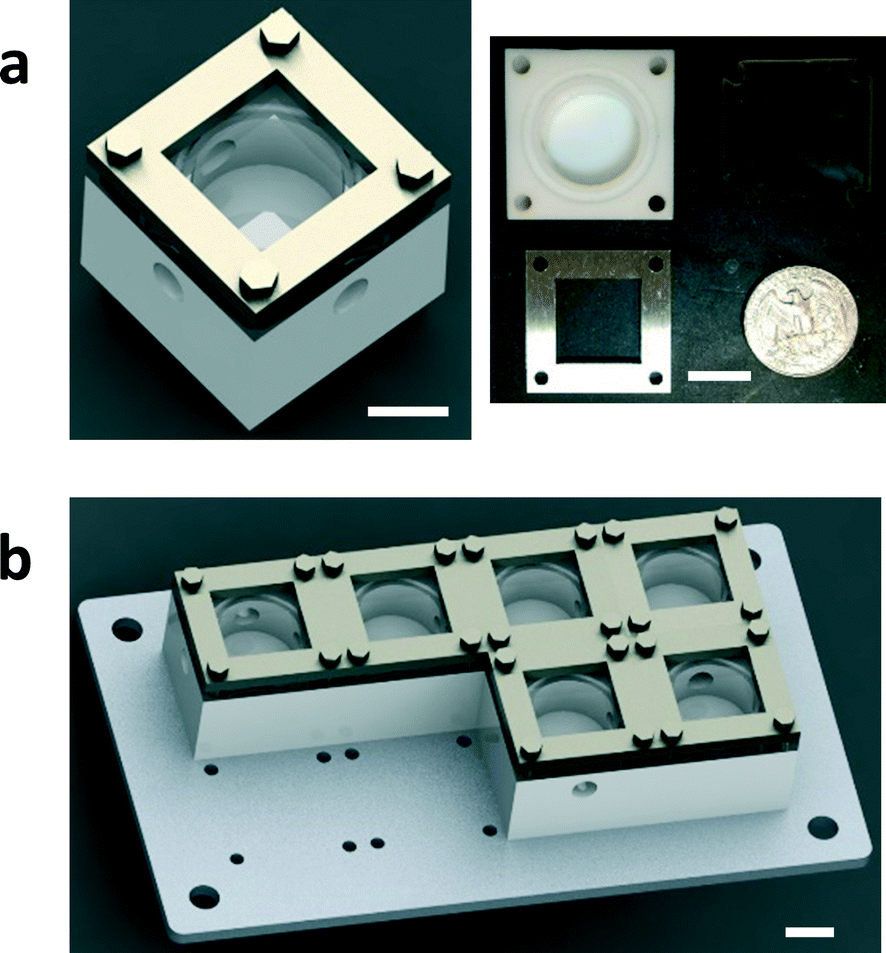 | ||
| Fig. 1 Sketch of the miniature CSTR cascade design. (a) The single-stage CSTR shown in CAD drawing, and the three main components of the actual product. (b) Multiple CSTRs in series on an aluminium holder. The white scale bars in the pictures above are 10 mm. | ||
Residence time distribution (RTD) characterization
The RTD profiles of the CSTR cascade were obtained using the pulse injection method (Fig. 2). The carrier phase was deionized (DI) water, and the tracer was methylene blue. In-line UV-Vis spectroscopy (light source: Ocean Optics, Inc., DH-2000-BAL; spectrometer: Ocean Optics, Inc., HR2000+) was used to determine the concentration profiles of the tracer at the inlet and outlet. A six-way valve (IDEX Health & Science LLC., MXP7900-000) combined with LabVIEW control enabled automatic pulse injection and data collection. | ||
| Fig. 2 Scheme of the residence time distribution measurement using in-line UV-Vis to record concentration profiles at the inlet and outlet. | ||
Procedure for predicting reaction conversions in the CSTR cascade
The scheme of the setup is shown in Fig. S1 (see the ESI†). Reagents for the Diels–Alder reaction (Scheme 1), isoprene and maleic acid anhydride, were prepared in the DMF solvent. The concentration of isoprene solution was 1.0 M and the concentration of maleic acid anhydride solution was 1.5 M. Two HPLC pumps (AZURA P 4.1S) were used to deliver reagent solutions into the reactor. Mineral wool was used to insulate the reactor in order to minimize the temperature gradient through the reactor wall. A thermocouple was placed between two reactor units to measure the reaction temperature. The product sample was diluted using ethyl acetate (1![[thin space (1/6-em)]](https://www.rsc.org/images/entities/char_2009.gif) :20) and cooled down to 0 °C in an ice bath in order to quench the reaction. Conversions were measured by gas chromatography (Agilent 6890).
:20) and cooled down to 0 °C in an ice bath in order to quench the reaction. Conversions were measured by gas chromatography (Agilent 6890).
 | ||
| Scheme 1 The Diels–Alder reaction of isoprene and maleic acid anhydride. | ||
General procedure for solid-forming reactions in the CSTR cascade
The scheme of the setup for continuous handling of solid-forming reactions in the CSTR cascade is shown in Fig. S2 (see the ESI†). The reagents for the reactions were dissolved into two separate solutions, which were pumped into the CSTR cascade by HPLC pumps. There was an in-line pressure sensor (Ashcroft G2) connected at the inlet of the reactor to measure the pressure profile in the reactor system. The CSTR cascade was placed on the magnetic stirrer to spin the magnetic stir bars in the CSTR chambers. Operating the CSTR cascade in the vertical mode helped to minimize clogging at the outlet of the reactor.Characterization of solid particles
An optical microscope (ZEISS Axiovert 200) was used to characterize the solid particles formed in the CSTR cascade. The particle size distributions were measured by means of a Malvern particle sizer (Malvern Mastersizer 2000). The same solvent was used to ensure that the particle size and morphology did not change when injecting the samples into the particle sizer.Results and discussion
Miniature CSTR cascade design
In the constructed miniature CSTR cascade system, each of the polytetrafluoroethylene (PTFE) reactor chambers has an inner diameter of 18 mm and holds a cross-shaped magnetic stirrer bar (Φ 9.5 mm × H 4.7 mm). For simplicity, a single magnetic stirrer plate provides the driving force for all stir bars. A more complex rotation system is also available to enable individual speed control for each stir bar (Fig. S4†). Based on the magnetic coupling force available from the stirrer plate, spinning the stir bar at a maximum speed of 600 rotations per minute (RPM) increases the local flow speed to keep particles suspended against gravity, particle–wall interaction, and particle–particle interaction. At the same time, agitation enhances mixing and heat transfer in each CSTR chamber. PTFE has good chemical compatibility suitable for common organic reactions, and the non-stick nature of PTFE contributes to reducing the particle–wall interactions to avoid build-up of particles on the reactor walls. The chamber is covered by heat-resistant borosilicate glass (Pyrex), allowing particle flow in the chamber to be viewed. In order to minimize the chances of clogging the 3.2 mm-diameter flow channel between two adjacent CSTR chambers, the units are placed in close contact to avoid interconnections becoming the threshold of the cascade. The system is simple to assemble for reactor cleaning and rearrangement.The residence time distribution (RTD) profile of the single-stage CSTR exhibits an exponential decay,38 which is usually undesired when side reactions exist in the system. A narrow RTD profile is favored for increasing yield and selectivity. Connecting CSTRs in series (Fig. 1b) narrows the RTD and approaches plug flow reactor (PFR) behavior for a large number of CSTRs.38 Thus, the RTD profile can be tuned from CSTR to PFR characteristics by choosing the number of CSTRs.
Assessment of mixing properties
Dead volume and bypass are two key factors that introduce non-ideality in CSTRs making it difficult to predict the performance for a given reaction. RTD measurements for different numbers of CSTRs in series yielded the expected trend of RTD profiles with increasing the reactor number (Fig. 3). The RTD profiles of a single CSTR and 3, 5, and 7 CSTRs in series were determined for constant mean residence time (reactor volume divided by the flow rate). | ||
| Fig. 3 RTD profiles of n = 1, 3, 5, and 7 CSTRs in series. Solid lines are regressed experimental RTD profiles based on the EMG model and dashed lines represent the profiles based on the ideal CSTRs in series model. | ||
Since the tracer pulse injected was not a perfect pulse, the outlet concentration profile was a convolution of the inlet concentration profile and RTD. The discrete fourier transform method would be preferred for deconvolution of the signals due to its simplicity, but noise in the data and the large number of data points introduced numerical errors. Therefore, we extracted the RTD from the inlet and outlet concentration profiles by model regression with the exponentially modified Gaussian (EMG) distribution model (eqn (1)). This model combines exponential decay and Gaussian distribution, which is generally suitable for RTD profiles that contain only one peak.39
 | (1) |
The outlet concentration profiles given by the convolution of the inlet concentration and regressed EMG model show excellent agreement with the experimentally measured outlet concentration profiles (Fig. S3†) showing that the EMG model is efficient in extracting the RTD profiles of the CSTR cascade. The tail of the outlet concentration profile becomes shorter when the number of CSTRs increases as expected since the cascade will approach plug flow reactor (PFR) behavior as the number of units becomes large.38
The mixing performance of the CSTRs was assessed by comparing the regressed EMG model to the RTD of the ideal CSTRs in series model (eqn (2)).38
 | (2) |
For the same number of CSTRs in series, the ideal and measured RTD profiles show high consistency (Fig. 3), which suggests that the agitation provided by the magnetic stir bar in each chamber is sufficient to achieve rapid mixing and reproduce the CSTR characteristics. In addition, the dead volume in the reactor is nearly negligible. The RTD profile becomes sharper with increasing number of CSTRs as expected. The nearly ideal CSTR cascade performance is essential for predicting the performance of an existing reaction system and rationally designing new processes.
Predicting reaction conversions in the CSTR cascade
Considering the nearly ideal CSTR mixing characteristics in each chamber of the miniature CSTR cascade, we decided to characterize the system by predicting reaction conversions based on reaction kinetics and RTD information. The Diels–Alder reaction between maleic acid anhydride and isoprene (Scheme 1) served as a model based on reported kinetic data.40–42The reaction temperature was set to 50 °C to have a moderate rate of reaction and significant differences in conversions for different residence times. We ran 1-, 3-, 5-, and 7-unit CSTR cascades at a constant flow rate of 400 μl min−1. Reaction conversions were computed based on reputed kinetic data (k = A × exp(−Ea/RT), A = (4.02 ± 2.5) × 106 L mol−1 s−1, Ea = 58.5 ± 2.0 kJ mol−1)41 along with an ideal CSTR cascade model. The experimental values fall at the lower side of the envelope of predicted conversions based on the reported uncertainty in rate constants (Fig. 4). The close agreement between predicted and measured conversions is consistent with the RTD results in Fig. 3. We attribute the lower than predicted conversions to the reaction temperature measured at the reactor outer wall, which would be slightly higher than the temperature of reactants inside the reactor given the external heating. Constructing the CSTR in stainless steel would reduce temperature gradients. We chose PTFE for its chemical compatibility and higher barrier for nucleation of solids on the walls.
 | ||
| Fig. 4 Comparison of measured and predicted reaction conversions for different numbers of CSTRs. Cross-hatched area: predicted conversions. Predicted conversions are based on an ideal CSTR cascade model. | ||
Continuous handling of reactions forming solids
We selected two reactions to assess the ability of the CSTR cascade to handle the formation of solids: (i) reaction of glyoxal with cyclohexylamine to form N,N′-dicyclohexylethylenediimine that is insoluble in the reaction solvent, ethanol (Scheme 2),19 and (ii) sulfonylation of 2-octanol (Scheme 3),43 for which the side product, triethylamine hydrochloride, has limited solubility in the solvent, dichloromethane (DCM).43 | ||
| Scheme 2 Imine formation reaction of glyoxal and cyclohexylamine. | ||
 | ||
| Scheme 3 Sulfonylation of 2-octanol with methanesulfonyl chloride. | ||
The first reaction (Scheme 2) tested the ability of the CSTR cascade to handle the formation of a solid product at relatively high solid loadings, 4.4% (wt), corresponding to stoichiometric amounts of the reagents and a glyoxal concentration of 0.4 M. The reaction reached nearly 100% conversion in 15 min with a 6-unit CSTR cascade. Adding more CSTRs after the 6-unit cascade would not lead to the growth of particles since the reaction was complete and, instead, help rebalance the particle size distribution. A total flow rate of 1 ml min−1, rapid stirring (∼600 RPMs), and short connections between adjacent chambers allowed transport of solid particles inside the CSTR cascade without clogging (Fig. 5). However, gravity caused particles to accumulate in the outlet tube. To avoid this problem and enable facile flow of particles through the entire system, the CSTR cascade was positioned vertically to align the gravity force and the outlet flow direction. As the reaction proceeded, the particle concentration in each chamber increased along the flow direction (Fig. 5).
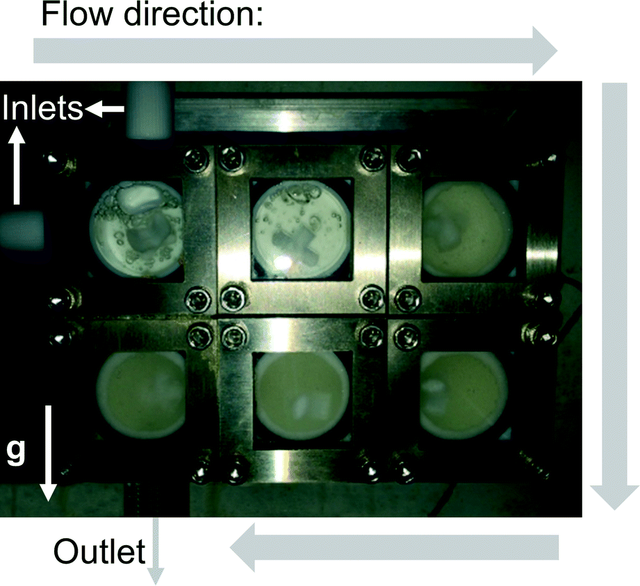 | ||
| Fig. 5 Photograph of the CSTR cascade during the operation showing the solid fraction increasing along the flow direction (the white arrow marked g shows the direction of gravity). | ||
Pressure measurement at the reactor inlet was a sensitive indicator of potential clogging problems. If particles built up in the reactor and clogged the flow path, the relative pressure would rise dramatically without going back. The system automatically would stop the pump to avoid damage to the pump or reactor when the pressure exceeded 10 bar. The pressure profile (Fig. 6a) demonstrates that the system could run continuously for 24 h without significant signs of clogging. Besides small pressure fluctuations in the reactor, a pressure spike occurred around 1000 min reflecting minor particle accumulation at the outlet and the solid clusters being pushed through by the elevated pressure. Once the particle clusters had left the system, the pressure returned to the base line. The solid product was an organic crystal, which had a slice-shaped morphology (Fig. 6b) and an average size of 226.7 μm with a standard deviation of 108.7 μm (Fig. 6c). Even though particles with sizes over 500 μm existed in the outlet stream, the larger interconnections (3.2 mm) and the limited amount of very large particles meant that they could flow through the interconnections without problems.
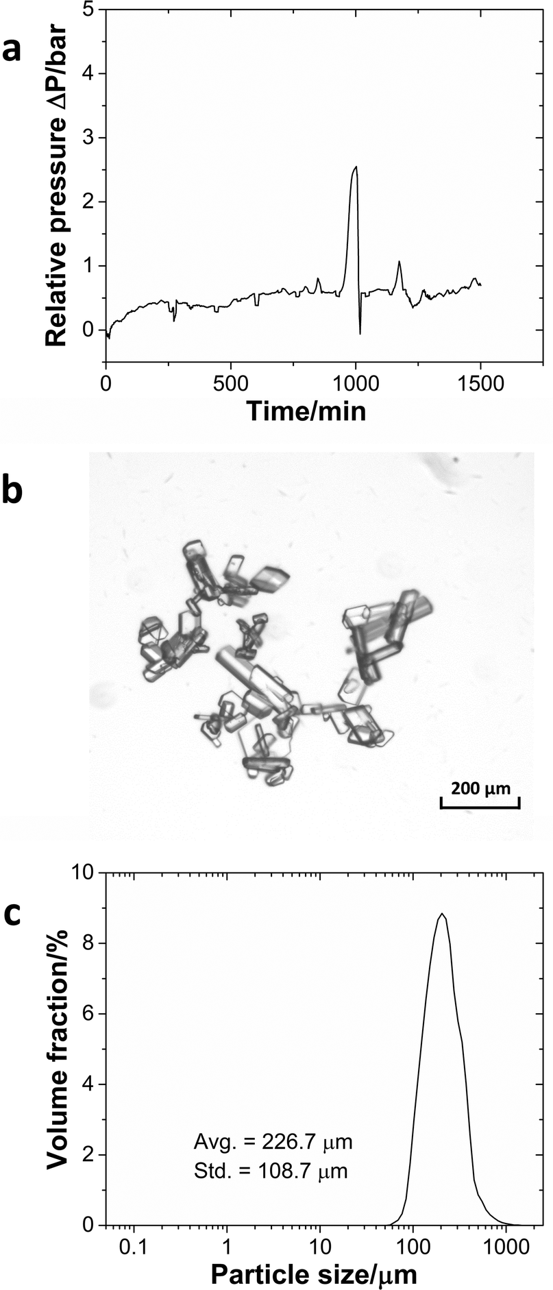 | ||
| Fig. 6 (a) Pressure profile during the continuous operation of the imine formation reaction. (b) Microscopy image of the imine crystal. (c) The particle size distribution of the product. | ||
In the previous case, the solid particles were the main product of the reaction. In the next example, sulfonylation of 2-octanol (Scheme 3), the side product, triethylamine hydrochloride, has limited solubility in the solvent, dichloromethane (DCM).43 Moreover, the crystals are needle-shaped (Fig. 7a) and thus agglomerate easily. When feasible, needle-shaped crystals are avoided in the pharmaceutical industry due to their poor flow properties. A 3-unit CSTR cascade sufficed to obtain full conversion at a flow rate of 1.00 ml min−1 of 0.6 M 2-octanol and 0.72 M methanesulfonyl chloride. Even with a solid loading of 4.1% (wt), the CSTR cascade ran continuously for 8 h without clogging, as reflected by the pressure profile (Fig. 7b).
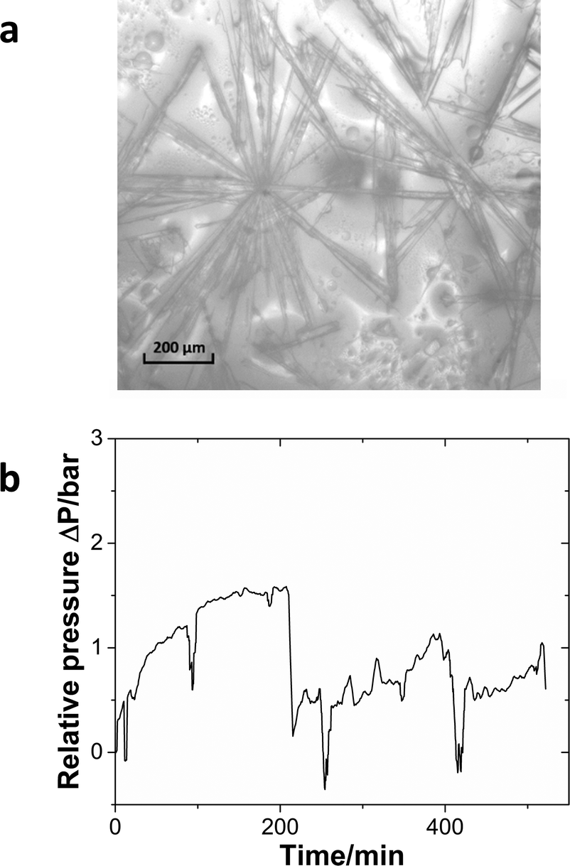 | ||
| Fig. 7 (a) The microscopy image of the triethylamine hydrochloride salt. (b) Relative pressure profile during the continuous operation of the sulfonylation reaction. | ||
Conclusion and perspectives
The case studies demonstrate the ability of the CSTR cascade to process reactions containing solids continuously. The reactor assembly, consisting of PTFE reactor chambers, glass and stainless steel covers, has excellent chemical resistance for most chemical reactions and is easy to clean after usage. The chambers' mount makes it easy to vary the number of units in the CSTR cascade. The homogeneous concentration and temperature profiles realized by strong agitation in each chamber result in nearly ideal CSTRs in series RTD profiles and accurate predictability of reaction conversions. Moreover, the high rate of stirring keeps the particles suspended in each reactor chamber, preventing them from sticking to the reactor wall or agglomerating. The short distance between adjacent reactor chambers minimizes the possibility of clogging at connections. Running the CSTR cascade in a vertical mode so that gravity aids particle transport out of the reactor eliminates clogging of the outlet tube. These rational design aspects contribute to the capability of long-time continuous handling of solids in the reactor. For different types of solid-forming reactions, such as rapid solid formation with fast growth kinetics, a careful investigation of suitable reaction conditions (e.g. reagent concentrations, reaction temperature, flow rates, etc.) needs to be performed in order for these reactions to proceed in the CSTR cascade.The capability to handle solids also enables its application to continuous crystallization, where tuning different operational parameters (e.g. rotation speed of stir bar and flow rates) can control the morphology of crystals in the CSTR cascade. The scope of the miniature CSTR cascade could be expanded by giving each unit a set of functions, such as independent temperature control and multi-injection points. Such modular units would enable telescoped multistep reactions in a single miniature CSTR cascade. Furthermore, the strong agitation in each chamber would also be beneficial for creating large contact areas and the resulting mass transfer for liquid–liquid reactions.
Acknowledgements
We thank the Novartis-MIT Center for Continuous Manufacturing for financial support.References
- B. Gutmann, D. Cantillo and C. O. Kappe, Angew. Chem., Int. Ed., 2015, 54, 6688–6728 CrossRef PubMed
.
- G. Wernet, S. Conradt, H. P. Isenring, C. Jiménez-González and K. Hungerbühler, Int. J. Life Cycle Assess., 2010, 15, 294–303 CrossRef
- D. M. Roberge, L. Ducry, N. Bieler, P. Cretton and B. Zimmermann, Chem. Eng. Technol., 2005, 28, 318–323 CrossRef
- J. Wegner, S. Ceylan and A. Kirschning, Chem. Commun., 2011, 47, 4583–4592 RSC
- T. Tsubogo, H. Oyamada and S. Kobayashi, Nature, 2015, 520, 329–332 CrossRef PubMed
- C. Wiles and P. Watts, Green Chem., 2012, 14, 38–54 RSC
- S. V. Ley and I. R. Baxendale, Nat. Rev. Drug Discovery, 2002, 1, 573–586 CrossRef PubMed
- K. Geyer, J. D. C. Codée and P. H. Seeberger, Chem. – Eur. J., 2006, 12, 8434–8442 CrossRef PubMed
- R. L. Hartman, J. P. McMullen and K. F. Jensen, Angew. Chem., Int. Ed., 2011, 50, 7502–7519 CrossRef PubMed
- S. V. Ley, D. E. Fitzpatrick, R. J. Ingham and R. M. Myers, Angew. Chem., Int. Ed., 2015, 54, 3449–3464 CrossRef PubMed
- S. V. Ley, D. E. Fitzpatrick, R. M. Myers, C. Battilocchio and R. J. Ingham, Angew. Chem., Int. Ed., 2015, 54, 10122–10136 CrossRef PubMed
- V. Hessel, D. Kralisch, N. Kockmann, T. Noël and Q. Wang, ChemSusChem, 2013, 6, 746–789 CrossRef PubMed
- D. R. Kaushal and Y. Tomita, Int. J. Multiphase Flow, 2002, 28, 1697–1717 CrossRef
- H. Cui and J. R. Grace, Int. J. Multiphase Flow, 2007, 33, 921–934 CrossRef
-
H. A. Nasr-El-Din, in Suspensions: Fundamentals and Applications in the Petroleum Industry, American Chemical Society, 1996, vol. 251, pp. 177–225 Search PubMed
- A. R. Oroskar and R. M. Turian, AIChE J., 1980, 26, 550–558 CrossRef
- R. L. Hartman, Org. Process Res. Dev., 2012, 16, 870–887 CrossRef
- S. Pal and A. A. Kulkarni, Chem. Eng. Sci., 2016, 153, 344–353 CrossRef
- S. L. Poe, M. A. Cummings, M. P. Haaf and D. T. McQuade, Angew. Chem., Int. Ed., 2006, 45, 1544–1548 CrossRef PubMed
- R. L. Hartman, J. R. Naber, N. Zaborenko, S. L. Buchwald and K. F. Jensen, Org. Process Res. Dev., 2010, 14, 1347–1357 CrossRef
- J. R. Naber, R. L. Hartman, J. P. McMullen, K. F. Jensen and S. L. Buchwald, Chem. Sci., 2011, 2, 287–290 RSC
- J. Sedelmeier, S. V. Ley, I. R. Baxendale and M. Baumann, Org. Lett., 2010, 12, 3618–3621 CrossRef PubMed
- S. Kuhn, T. Noël, L. Gu, P. L. Heider and K. F. Jensen, Lab Chip, 2011, 11, 2488–2492 RSC
- N. Pamme and C. Wilhelm, Lab Chip, 2006, 6, 974–980 RSC
- A. I. Rodríguez-Villarreal, M. D. Tarn, L. A. Madden, J. B. Lutz, J. Greenman, J. Samitier and N. Pamme, Lab Chip, 2011, 11, 1240–1248 RSC
- N. Pamme, Lab Chip, 2006, 6, 24–38 RSC
- J. G. Kralj, M. T. W. Lis, M. A. Schmidt and K. F. Jensen, Anal. Chem., 2006, 78, 5019–5025 CrossRef PubMed
- M. Dürr, J. Kentsch, T. Müller, T. Schnelle and M. Stelzle, Electrophoresis, 2003, 24, 722–731 CrossRef PubMed
- D. L. Browne, B. J. Deadman, R. Ashe, I. R. Baxendale and S. V. Ley, Org. Process Res. Dev., 2011, 15, 693–697 CrossRef
- B. J. Deadman, D. L. Browne, I. R. Baxendale and S. V. Ley, Chem. Eng. Technol., 2015, 38, 259–264 CrossRef CAS
- P. Filipponi, A. Gioiello and I. R. Baxendale, Org. Process Res. Dev., 2015, 20, 371–375 CrossRef
- L. Liguori and H.-R. Bjørsvik, Org. Process Res. Dev., 2011, 15, 997–1009 CrossRef CAS
- R. Spaccini, L. Liguori, C. Punta and H.-R. Bjørsvik, ChemSusChem, 2012, 5, 261–265 CrossRef CAS PubMed
- G. Morris, G. Power, S. Ferguson, M. Barrett, G. Hou and B. Glennon, Org. Process Res. Dev., 2015, 19, 1891–1902 CrossRef CAS
- Y. Yang and Z. K. Nagy, Chem. Eng. Sci., 2015, 127, 362–373 CrossRef CAS
- Y. Yang and Z. K. Nagy, Ind. Eng. Chem. Res., 2015, 54, 5673–5682 CrossRef CAS
- A. J. Alvarez, A. Singh and A. S. Myerson, Cryst. Growth Des., 2011, 11, 4392–4400 CAS
-
O. Levenspiel, Chemical reaction engineering, Wiley, New York, 3rd edn, 1999 Search PubMed
- Q. Yang, A. Drak, D. Hasson and R. Semiat, J. Membr. Sci., 2007, 306, 355–364 CrossRef CAS
- J. P. McMullen and K. F. Jensen, Org. Process Res. Dev., 2011, 15, 398–407 CrossRef CAS
- W. Hoffmann, Y. Kang, J. C. Mitchell and M. J. Snowden, Org. Process Res. Dev., 2007, 11, 25–29 CrossRef CAS
- M. G. Silvestri and C. E. Dills, J. Chem. Educ., 1989, 66, 690 CrossRef CAS
- Y. Yoshida, Y. Sakakura, N. Aso, S. Okada and Y. Tanabe, Tetrahedron, 1999, 55, 2183–2192 CrossRef CAS
Footnote |
| † Electronic supplementary information (ESI) available. See DOI: 10.1039/c6re00132g |
| This journal is © The Royal Society of Chemistry 2016 |