
A spray-drying continuous-flow method for simultaneous synthesis and shaping of microspherical high nuclearity MOF beads†
L.
Garzón-Tovar
a,
M.
Cano-Sarabia
a,
A.
Carné-Sánchez
a,
C.
Carbonell
a,
I.
Imaz
*a and
D.
Maspoch
*ab
aCatalan Institute of Nanoscience and Nanotechnology (ICN2), CSIC and The Barcelona Institute of Science and Technology, Campus UAB, Bellaterra, 08193 Barcelona, Spain. E-mail: inhar.imaz@icn.cat; daniel.maspoch@icn.cat
bICREA, Pg. Lluís Companys 23, 08010 Barcelona, Spain
First published on 19th July 2016
Abstract
Metal–organic frameworks (MOFs) are among the most attractive porous materials currently available. However, one of the challenges precluding their industrial exploitation is the lack of methods for their continuous production. In this context, great advances have been enabled by recently discovered, novel continuous-fabrication methods such as mechanosynthesis, electrochemistry, continuous-flow synthesis and spray-drying. Herein we report the benefits of coupling two of these processes—spray-drying and continuous flow—for continuous synthesis of MOFs assembled from high-nuclearity secondary building units (SBUs). Using the resulting spray-drying continuous flow-assisted synthesis, we have prepared numerous members of diverse MOF families, including the UiO-66, Fe–BTC/MIL-100 and [Ni8(OH)4(H2O)2(L)6]n (where L = 1H-pyrazole-4-carboxylic acid) series. Interestingly, all of these MOFs were automatically obtained as compact microspherical superstructures (beads). We anticipate that our strategy could be easily employed for synthesizing and shaping multivariate (MTV) MOFs.
Introduction
Metal–organic frameworks (MOFs) are an emerging class of crystalline porous materials that have garnered major interest due to their varied chemical composition, diverse pore sizes and shapes, large surface areas, tailored internal surfaces, and flexible structures. These properties make MOFs potentially useful for myriad applications, including gas storage, separation, catalysis, molecular sensing, heat-pump processes, contaminant removal, and drug delivery.1–6 However, despite these possibilities, the industrial applicability and economic feasibility of MOFs are currently limited, owing to a dearth of practical and cost-effective methods for pilot-scale synthesis. In this context, one approach that has traditionally been proposed for MOFs is solvothermal synthesis, which is usually conducted in closed reactors. However, other processes have recently begun to be developed in the hopes of achieving continuous, solvent-free and/or green synthesis of MOFs. These methods basically include mechanosynthesis,7,8 electrochemistry,9 continuous-flow techniques10,11 and spray-drying,12,13 some of which obviate the toxic solvents or cumbersome filtration of earlier methods.We recently reported that the well-known industrial technique of spray-drying can also be considered as a general, low-cost and scalable method for the continuous synthesis of MOFs in the form of spherical structures, nanoparticles and composites.12 Initially, we found that this methodology enables the production—even up to the kilogram scale—of archetypical MOFs such as HKUST-1 and related paddle-wheel Cu(II)-based MOFs (e.g. Cu–BDC, NOTT-100) in high yields and without any loss of sorption capabilities. We also found that this method could be extended to other MOF families such as MILs, UiOs, and ZIFs. However, whilst most MOFs could be synthesised via spray-drying, MOFs assembled from high-nuclearity second-building units (SBUs) are a more challenging target. Indeed, most of our attempts at spray-drying synthesis of these materials result in low yields and/or poor sorption capabilities. We attributed this problem chiefly to the inherently rapid drying kinetics in spray-drying, which complicate the formation of high nuclearity SBUs. In fact, several studies have suggested that the formation of SBUs is cardinal in MOF assembly, as they are most likely required for the nucleation and subsequent crystal growth of MOFs.14–16
Herein we describe an updated version of our spray-drying method, which enhances the production of high-nuclearity MOFs. Specifically, by introducing a continuous-flow reactor at the entrance of the spray dryer (Fig. 1a and b), we have devised a continuous two-step method that combines the benefits of both systems. It works as follows: firstly, the precursor solution containing the metal salt and the organic linker is injected into a continuous coil flow reactor encased in a thermostatic oil tank, where it is heated at a certain temperature (T1) to promote SBU formation and nucleation. Here, the residence time (t) of the precursor solution in the coil flow reactor is controlled by the rate of the pump (the feed rate). Since the outlet flow of the reactor is directly connected to the nozzle of the spray-dryer, the pre-heated solution is automatically injected into the spray-drier at the same feed rate. The solution is then atomised using a two-fluid nozzle and dried at a certain temperature (T2) and flow rate, such that the MOF growth is confined to individual micro-reactors (i.e. the atomised droplets).12 The whole continuous process enables the collection of dried MOFs shaped in the form of microspherical superstructures (beads). Furthermore, the solvent used can simply be recovered, making the process both cost- and waste-efficient.
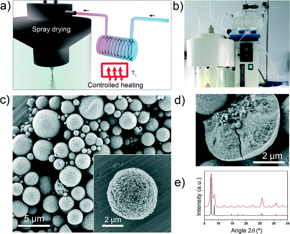 | ||
| Fig. 1 (a, b) Schematic illustration (a) and photograph (b) showing the set-up for spray-drying continuous flow-assisted synthesis of high-nuclearity MOFs. (c) Representative FESEM images of microspherical UiO-66 beads prepared by this process. Inset: a single UiO-66 bead. (d) FESEM image of a mechanically broken bead, revealing the dense core. (e) XRPD diffractogram of UiO-66 powder (red), as compared to the corresponding simulated powder pattern (black). Scale bars: 5 μm (c) and 2 μm (d, and c, inset). | ||
We first demonstrated the performance of our new method by assembling several members of the UiO-66 series, including the iconic UiO-6617 and related MOFs UiO-66-NH2,18 UiO-66-NO2,18 UiO-66-acetamido,19 UiO-66-Br,18 UiO-66-(OH)2,20 UiO-66-1,4-NDC (where 1,4-NDC is 1,4-naphthalenedicarboxylate)19 and UiO-66-2,6-NDC (where 2,6-NDC is 2,6-naphthalenedicarboxylate).21,22 We then extended the synthesis to other high-nuclearity MOFs such as Fe–BTC/MIL-10023 and [Ni8(OH)4(H2O)2(L)6]n (where L = 1H-pyrazole-4-carboxylic acid).24 These examples cover some of the best-known MOFs built from high-nuclearity metal clusters. We envision that by introducing different organic linkers into the MOF precursor solution before the synthesis begins, we should be able to use our spray-drying continuous-flow method to prepare microspherical multivariate (MTV) MOFs.25,26
Results and discussion
We began with the synthesis of UiO-66, a robust, closely-packed, three-dimensional cubic MOF assembled by connecting hexanuclear [Zr6O4(OH)4] oxoclusters through 1,4-terephthalate (BDC) linkers.27 UiO-66, which typically exhibits surface areas (SBET) ranging from 1100–1250 m2 g−1,17 has already been synthesised by various methods, including solvothermal (typical yields = 90–97%; reaction time = 24 h),28,29 hydrothermal (yield = 63%; reaction time = 24 h),30 and continuous flow (yield = 63%) syntheses.11 In our optimised spray-drying continuous flow-assisted synthesis of UiO-66, a precursor solution containing ZrCl4, BDC, H2O and DMF in a molar ratio of 1![[thin space (1/6-em)]](https://www.rsc.org/images/entities/char_2009.gif) :1:40:135 (concentration of ZrCl4 = 0.1 M) was injected into the coil flow reactor at a feed rate of 2.4 mL min−1 and at a T1 of 115 °C. The residence time inside the coil flow reactor was 63 s. The resulting pre-heated solution was then spray dried at a T2 of 180 °C and a flow rate of 336 ml min−1, using a B-290 Mini Spray Dryer (BUCHI Labortechnik), immediately affording a white powder. This powder was washed with DMF and ethanol, and finally dried at 80 °C (yield = 70%). Note here that, under these optimized conditions, the space-time yield (STY) is 19.6 kg m−3 d−1. This STY is much higher than that previously reported using the conventional spray drying method (4.0 kg m−3 d−1), in which the reactant solution was also preheated for two hours before spraying.12
:1:40:135 (concentration of ZrCl4 = 0.1 M) was injected into the coil flow reactor at a feed rate of 2.4 mL min−1 and at a T1 of 115 °C. The residence time inside the coil flow reactor was 63 s. The resulting pre-heated solution was then spray dried at a T2 of 180 °C and a flow rate of 336 ml min−1, using a B-290 Mini Spray Dryer (BUCHI Labortechnik), immediately affording a white powder. This powder was washed with DMF and ethanol, and finally dried at 80 °C (yield = 70%). Note here that, under these optimized conditions, the space-time yield (STY) is 19.6 kg m−3 d−1. This STY is much higher than that previously reported using the conventional spray drying method (4.0 kg m−3 d−1), in which the reactant solution was also preheated for two hours before spraying.12
Field-emission scanning electron microscopy (FESEM) images and X-ray powder diffraction (XRPD) patterns of the resulting solid revealed the homogeneous formation of UiO-66 in the form of spherical beads (Fig. 1c–e and S1†). These microscale beads comprise multiple UiO-66 nanoparticles, contain a dense core, and have an average diameter of 4.3 ± 2.6 μm (Fig. S1†). The microporosity of the synthesised UiO-66 was confirmed by nitrogen-adsorption measurements, which gave an SBET value of 1106 m2 g−1 (Fig. S2†). This value is consistent with previously reported values,17 thus confirming the quality of our synthesised UiO-66.
We would like to point out that the spherical MOF superstructures (beads) that we prepared using our spray-drying continuous flow-assisted process are highly compact, unlike the hollow superstructures that we had previously obtained by spray-drying.12 We attribute this difference to the formation, inside the reactor, of a suspension containing a primary nucleus. In a general spray-drying process, the atomised droplets are exposed to hot air, the solvent evaporates and consequently, the droplet surface shrinks.31 During this process, hollow superstructures are formed when there is a non-linear change in precursor concentration at the droplet: specifically, it causes the formation of an impermeable shell and the generation of gas at the core.32,33 However, in our case, uniform precursor concentration and droplet temperature are reached, owing to the presence of the uniformly-distributed nuclei in the droplet. The rate at which the nucleus can be brought to the surface by diffusion is lower than the rate at which the nucleus can grow during the drying–evaporation process. This difference favours a linear change in precursor concentration and temperature at the droplet, and consequently, drives the formation of dense superstructures.
To prove that the effective synthesis of UiO-66 results from using both techniques in tandem, rather than simply from one of them, we separately performed the spray-drying step and the continuous-flow step using the aforementioned conditions. Spray-drying alone afforded a non-porous amorphous solid (Fig. S3†), whereas continuous-flow synthesis alone provided UiO-66 (Fig. S4†), albeit in a much lower yield (12%) and quality (SBET = 708 m2 g−1) than that obtained when the two methods were combined.
To optimise the synthesis of a given MOF using our spray-drying continuous flow-assisted method, one can adjust the standard reaction parameters: the reagents and solvents used, the stoichiometry of the precursor solution, and the concentration of the precursors. Moreover, one can tune method-specific parameters such as the residence time (t), the two temperatures (T1 and T2), and the flow rate. Accordingly, we began our optimisation of the synthesis of UiO-66 by selecting ZrCl4 and BDC as reagents, DMF and H2O as solvents, an initial concentration of 0.1 M for both reagents, a final molar ratio (Zr/BDC/H2O/DMF) of 1:1:30:135, a T1 of 115 °C, a T2 of 180 °C, and a flow rate of 336 ml min−1. It is important to highlight here that we introduced water into the precursor solution because it is known to favour the formation of UiO-66.20,29 Also, we selected a concentration of 0.1 M because it is the maximum concentration that has already been demonstrated for the continuous flow synthesis of UiO-66.11,34 We chose a T2 of 180 °C because it is the minimum temperature needed to fully evaporate DMF inside the spray-drier, and we chose a flow rate of 336 ml min−1 because we had previously found it to be optimal for the spray-drying synthesis of MOFs.12
Using the pre-defined conditions described above, we sought to optimise the residence time (t) of the precursor solution in the coil flow reactor. To this end, we systematically varied t (35, 41, 48, 63, 94 or 130 s, which correspond to feed rates of 4.5, 3.6, 3.0, 2.4, 1.8 or 1.2 ml min−1, respectively) to evaluate its effect on the purity, yield and SBET of the synthesised UiO-66 (Table S1; Fig. S5†). We found that the optimal t value was 63 s. Interestingly, we observed clogging effects at t values of 94 s and 130 s, which we ascribed to the formation of large precipitates of UiO-66 inside the coil flow reactor. Importantly, we observed that at 94 s and 130 s, the UiO-66 (most of which had been synthesised in the coil flow reactor) exhibited much lower SBET values (667 and 687 m2 g−1, respectively) than that produced at t = 63 s (1044 m2 g−1). This observation was crucial because it further confirmed the benefits of the spray-drying step in the crystal growth of UiO-66. Indeed, when we reproduced the reaction using only the continuous-flow process (without the spray drying step; residence time = 94 s), UiO-66 was obtained in relatively high yield (58%, Fig. S6†) but with a low SBET value (610 m2 g−1), which was comparable to that obtained with the spray-drying continuous flow-assisted method using the same residence time. This result confirmed that as the residence time increases, the proportion of UiO-66 synthesised in the coil flow reactor increases and the quality of the product decreases.
Having determined the optimum residence time for the spray-drying continuous flow-assisted synthesis of UiO-66, we then studied the effects of H2O as a co-solvent by varying the equivalents of it (x = 20, 30, 40, 45 or 50; see Table S2 and Fig. S7†) in the Zr/BDC/H2O/DMF (molar ratio = 1:1:x:135) precursor solution. As expected,20,29 we found that increasing the amount of H2O led to better yields: thus at x = 40, the yield was 70% (SBET = 1106 m2 g−1), and at x = 45, the yield was 84% (SBET = 963 m2 g−1). However, we could not surpass a value of x = 50, the value at which the precursor solution begins to boil inside the coil flow reactor, consequently impeding its correct flow.
Finally, we also studied the effect of T1 in the coil flow reactor, by decreasing the value from 115 °C to 90 °C (Table S3 and Fig. S8†). We observed that this decrease causes a decrease in the yield and in the SBET. This observation was very important because it corroborated that a minimum T1 is required in the coil flow reactor to generate sufficient energy to induce nucleation.
To demonstrate the generality of our approach for high-nuclearity MOFs, we used it to synthesise several other members of the UiO-66 series, including UiO-66-NH2, UiO-66-NO2, UiO-66-acetamido, UiO-66-Br, UiO-66-(OH)2, UiO-66-1,4-NDC and UiO-66-2,6-NDC. Fig. 2a–d and f show typical FESEM images of the resulting microspherical beads (0.5–5.9 μm) created by the close packing of smaller crystals (Fig. S9 and Table S4†). The different samples reveal a rather broad size distribution. This is mainly because the synthetic conditions used for each UiO-66 were optimized to synthesise them in a good quality and yield instead of optimizing the droplet size distribution, a parameter that usually depends on the liquid viscosity, surface tension, mass rate of atomization air and liquid feed rate. For all synthesised members of the UiO-66 series, XRPD studies confirmed their phase purity (Fig. 2e and g), whereas nitrogen physical adsorption confirmed their microporosity: all the calculated BET surface areas were similar to previously reported values (Fig. 2h and S10–S16†).
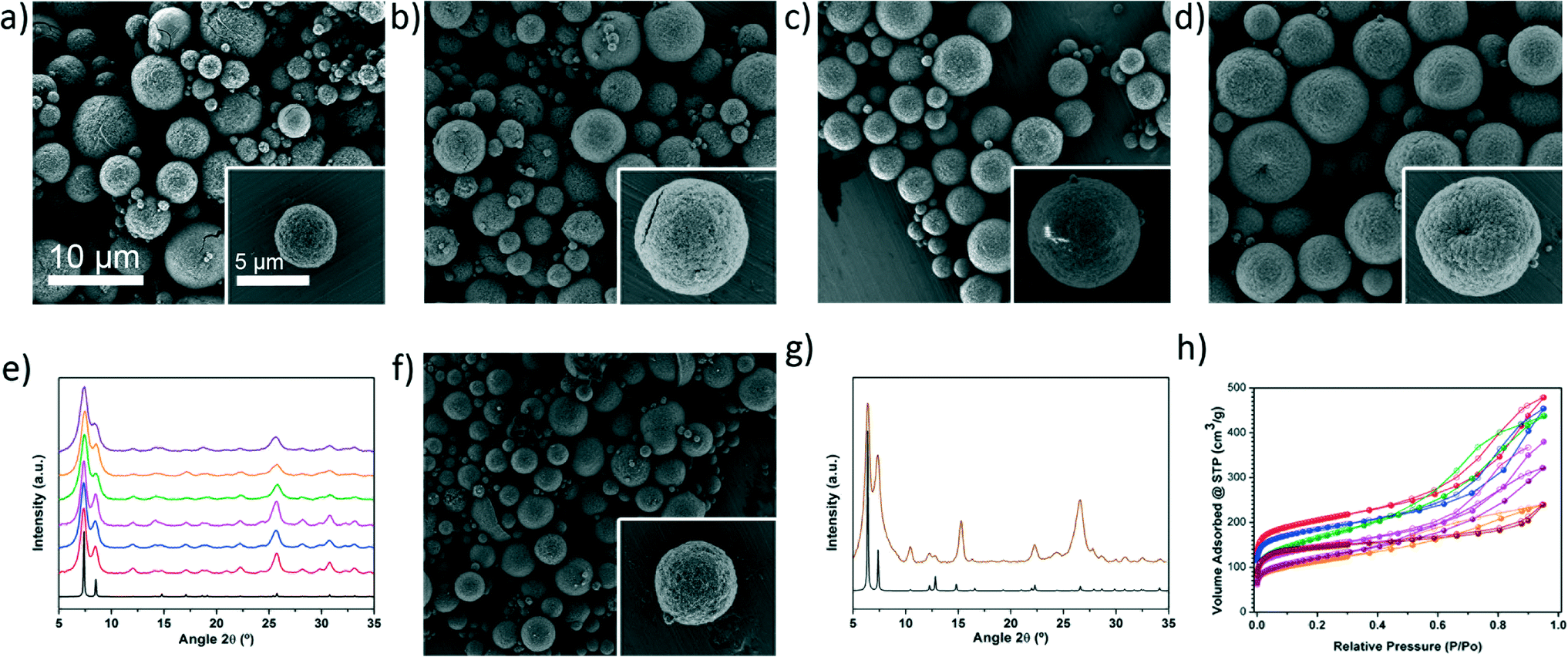 | ||
| Fig. 2 Representative FESEM images showing the microspherical beads of a) UiO-66-NH2, b) UiO-66-NO2, c) UiO-66-Br, d) UiO-66-(OH)2, and f) UiO-66-2,6-NDC. e) XRPD diffractograms of the UiO-66 series (red: UiO-66-NH2, blue: UiO-66-NO2, pink: UiO-66-Br, green: UiO-66-acetamido, orange: UiO-66-(OH)2, purple: UiO-66-1,4-NDC), as compared to the simulated powder pattern for UiO-66 (black). g) XRPD diffractogram of UiO-66-2,6-NDC (coffee), as compared with the simulated pattern (black). h) N2 adsorption isotherms of the synthesised UiO-66 series (red: UiO-66-NH2, blue: UiO-66-NO2, pink: UiO-66-Br, green: UiO-66-acetamido, orange: UiO-66-(OH)2, purple: UiO-66-1,4-NDC, coffee: UiO-66-2,6-NDC). Scale bars: 10 μm (all images) and 5 μm (all insets). | ||
We then extended our synthesis of high-nuclearity MOFs to Fe–BTC/MIL-100 and [Ni8(OH)4(H2O)2(L)6]n, whose SBUs are a trinuclear iron cluster and an octanuclear nickel cluster, respectively. Microspherical beads of Fe–BTC/MIL-100 were obtained in very high yield (78%) and with a SBET value of 1039 m2 g−1 (Fig. 3b and d and S17†). We would like to point out to the reader that, whilst the XRD pattern exhibited low crystallinity and the SBET value is much lower than the value obtained for Fe–BTC/MIL-100 synthesised under solvothermal conditions (SBET = 2200 m2 g−1), it is nevertheless comparable to that of the commercially available material Basolite F300 (maximum SBET = 1040 m2 g−1)35,36 and to that of the material previously synthesised by spray-drying (SBET = 600 or 1010 m2 g−1).13 However, unlike the previously reported spray-drying synthesis, our spray-drying continuous flow-assisted method does not require the use of surfactants. Alternatively, [Ni8(OH)4(H2O)2(L)6]n was obtained as a highly crystalline material (yield = 60%; see Fig. 3a and c and S18†), with a higher SBET value (377 m2 g−1) than that previously reported (205 m2 g−1).24
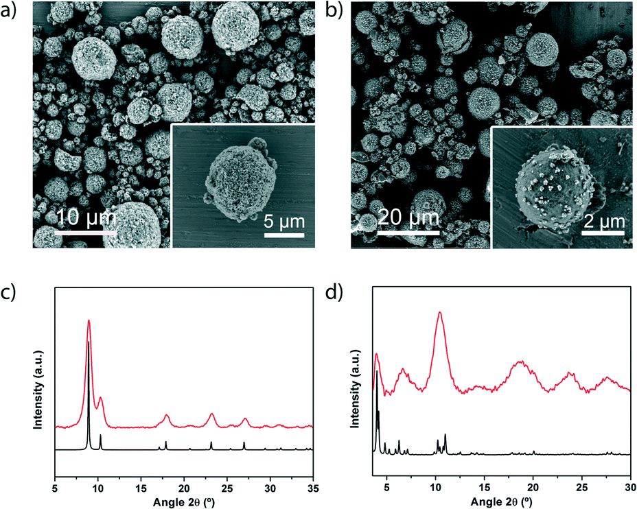 | ||
| Fig. 3 (a) Representative FESEM images showing a general view of the microspherical beads of a) [Ni8(OH)4(H2O)2(L)6]n and b) MIL-100. c) XRPD diffractogram of the obtained powder compared with the simulated powder pattern of [Ni8(OH)4(H2O)2(L)6]n (black). d) XRPD diffractogram of the obtained powder compared with the simulated powder pattern of MIL-100. Scale bars: 10 μm (a) and 20 μm (b). Insets: 5 μm (a) and 2 μm (b). | ||
Having demonstrated that our spray-drying continuous flow-assisted method enables the formation of high-nuclearity microspherical MOFs, we pondered whether it could also be used for the synthesis of MTV MOFs that would combine the characteristics of different organic linkers. To explore this possibility, we reproduced the spray-drying continuous flow-assisted synthesis of UiO-66, except that instead of pure BDC, we used a mixture of BDC and Br-BDC, testing different BDC/BDC-Br molar ratios (1:0.5, 1:1 or 1:2). In all cases, FESEM and XRPD of the resulting white solids confirmed the formation of the characteristic beads made of pure UiO-66-type phase (Fig. 4a, b and S19†). Quantitative analyses of the digested microspherical beads by 1H-NMR spectroscopy (Fig. 4c and S20†) confirmed that both linkers were present in the synthesised MTV-UiO-66 samples, revealing BDC/BDC-Br molar ratios of 1:0.6, 1:1.3 or 1:2.3. Interestingly, these ratios were close to those expected from the corresponding input ratios used in the reaction mixtures. We further studied the porosity of all the synthesised MTV-UiO-66 through nitrogen sorption measurements conducted at 77 K. Remarkably, all the products were porous to N2. As expected, the SBET values decreased with increasing equivalents of BDC-Br: 818 m2 g−1 for 0.6; 678 m2 g−1 for 1.3; and 570 m2 g−1 for 2.3 (Fig. 4d and S21–S23†). We attributed this trend to an increase in steric hindrance resulting from the introduction of more (bulky) BDC-Br linkers into the UiO-66 framework.
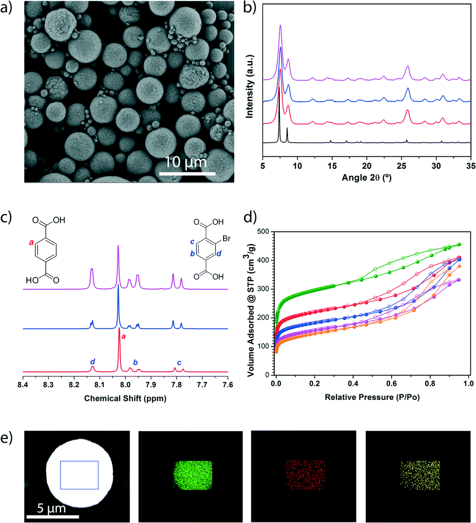 | ||
| Fig. 4 (a) Representative FESEM image showing a general view of the microspherical beads of the MTV-UiO-66 with a BDC/BDC-Br molar ratio of 1:0.6. b) XRPD diffractograms of the MTV-UiO-66 collected after their synthesis at different BDC/BDC-Br molar ratios (red: 1:0.6, blue: 1:1.3, pink: 1:2.3), as compared to the simulated powder pattern for UiO-66 (black). c) 1H-NMR spectra of the digested samples of the MTV-UiO-66 synthesised at different BDC/BDC-Br molar ratios (red: 1:0.6, blue: 1:1.3, pink: 1:2.3). d) N2 adsorption isotherms of the synthesised UiO-66 (green), UiO-66-Br (orange) and MTV-UiO-66 at different BDC/BDC-Br molar ratios (red: 1:0.6, blue: 1:1.3, pink: 1:2.3). e) Elemental mapping with EDX performed on a single spherical bead of MTV-UiO-66 (BDC, BDC-Br and BDC-NH2), showing the homogeneous distribution of Zr (green), Br (red) and N (yellow). Scale bar: 10 μm (a) and 5 μm (e). | ||
Finally, we sought to increase the complexity of the synthesised MTV-UiO-66 by mixing the BDC, BDC-Br and BDC-NH2 linkers at a molar ratio of 1:1:1. Again, FESEM and XRPD of the resulting product (a yellow solid) revealed the formation of microspherical beads made of pure UiO-66-type phase, whereas the 1H NMR spectrum confirmed the presence of the three linkers at a molar ratio (BDC/BDC-Br/BDC-NH2) of 1:1.1:0.6 (Fig. S19, S24, and S25†). The presence of these linkers was further confirmed by elemental mapping with energy dispersive X-ray spectrometry (EDX) performed on a single bead, which revealed a highly uniform distribution of Zr, Br and N atoms (Fig. 4e). Additionally, this MOF was found to be porous to N2, exhibiting an SBET of 707 m2 g−1 (Fig. S26†).
Conclusions
In conclusion, we have reported an updated version of our spray-drying methodology for MOF fabrication, which enables simultaneous synthesis and shaping of microspherical high-nuclearity MOF beads. This new method is based on incorporating a continuous flow reactor at the entrance of the spray-drier. It thus combines the advantages of continuous flow to those of spray-drying, providing MOFs in good yields, with excellent porosity and highly dense cores. Furthermore, it is amenable to the fabrication of MTV MOFs, thereby opening up new avenues for fine-tuning the porosity of these materials. We hope that our new method, together with existing ones (e.g. mechanosynthesis, electrochemistry, and continuous-flow chemistry), will facilitate the industrial development and exploitation of MOFs.Experimental section
Materials and methods
Zirconium chloride, nickel acetate tetrahydrate, iron(III) nitrate nonahydrate, terephthalic acid, 2-aminoterephthalic acid, 2-bromoterephthalic acid, 2-nitroterephthalic acid, 2,5-dihydroxyterephthalic acid, 1,4-naphthalenedicarboxylic acid, 2,6-naphthalenedicarboxylic acid, benzene-1,3,5-tricarboxylic acid and 1H-pyrazole-4-carboxylic acid were purchased from Sigma Aldrich. Dimethylformamide was obtained from Fisher Chemical. All the reagents were used without further purification. Deionised water, obtained with a Milli-Q® system (18.2 MΩ cm), was used in all reactions. 2-Acetamidoterephthalic acid was synthesised according to a reported procedure.37X-ray powder diffraction (XRPD) patterns were collected on an X'Pert PRO MPDP analytical diffractometer (Panalytical) at 45 kV and 40 mA using CuKα radiation (λ = 1.5419 Å). Nitrogen adsorption and desorption measurements were performed at 77 K using an Autosorb-IQ-AG analyser (Quantachrome Instruments). Field-emission scanning electron microscopy (FESEM) images were collected on a FEI Magellan 400 L scanning electron microscope at an acceleration voltage of 2.0 KV and a FEI Quanta 650F scanning electron microscope at an acceleration voltage of 20.0 KV, using aluminium as a support. 1H NMR spectra were acquired on a Bruker Avance DRX-250 spectrometer, using a solution prepared by digesting 10 mg of sample in a mixture of 48% HF (20 μL) and DMSO-d6 (600 μL). The size distributions were determined by laser diffraction (LD) on a Mastersizer2000 (Malvern Instruments).
Spray-drying continuous flow-assisted synthesis of UiO-66 series
In a typical synthesis, a solution of 0.1 M ZrCl4 and 0.1 M organic ligand in 15 ml of a mixture of DMF and H2O (5.48:1) was injected into the coil flow reactor (Pyrex tube, inner diameter: 3 mm) at a feed rate of 2.4 ml min−1 and at a T1 of 115 °C. The resulting pre-heated solution was then spray-dried at a T2 of 180 °C and a flow rate of 336 ml min−1 using a Dryer B-290 Mini Spray (BUCHI Labortechnik; spray cap: 0.5 mm-hole). Finally, the collected solid was dispersed in DMF at room temperature under stirring overnight and precipitated by centrifugation. This process was repeated twice with ethanol instead of DMF. The final product was dried for 12 h at 80 °C. UiO-66: yield = 70%; purity = 54%; SBET = 1106 m2 g−1. UiO-66-NH2: yield = 67%; purity = 49%; SBET = 752 m2 g−1. UiO-66-NO2: yield = 62%; purity = 49%; SBET = 679 m2 g−1. UiO-66-acetamido: yield = 51%; purity = 41%; SBET = 586 m2 g−1. UiO-66-Br: yield = 68%; purity = 62%; SBET = 527 m2 g−1. UiO-66-(OH)2: yield = 81%; purity = 67%; SBET = 401 m2 g−1. UiO-66-1,4-NDC: yield = 45%; purity = 45%; SBET = 431 m2 g−1. UiO-66-2,6-NDC: yield = 49%; purity = 37%; SBET = 557 m2 g−1.
Spray-drying continuous flow-assisted synthesis of [Ni8(OH)4(H2O)2(L)6]n
A solution of 0.02 M Ni(CH3COO)2·4H2O and 0.015 M 1H-pyrazole-4-carboxylic acid in 20 ml of a mixture of DMF and H2O (4:1) was injected into the coil flow reactor (Pyrex tube, inner diameter: 3 mm) at a feed rate of 2.4 ml min−1 and at a T1 of 100 °C. The resulting pre-heated solution was then spray-dried at a T2 of 180 °C and a flow rate of 336 ml min−1 using a B-290 Mini Spray Dryer (BUCHI Labortechnik; spray cap: 0.5 mm-hole). Finally, the collected solid was dispersed in EtOH and precipitated by centrifugation. This two-step washing process was repeated with Et2O. The final product was dried for 12 h at 60 °C. Yield = 60%; purity = 81%; SBET = 377 m2 g−1.
Spray-drying continuous flow-assisted synthesis of Fe–BTC/MIL-100
A solution of 0.1 M Fe(NO3)3·9H2O and 0.07 M BTC in 15 ml of DMF was injected into the coil flow reactor (Pyrex tube, inner diameter: 3 mm) at a feed rate of 2.4 ml min−1 and at a T1 of 135 °C. The resulting pre-heated solution was then spray-dried at a T2 of 180 °C and a flow rate of 336 ml min−1 using a B-290 Mini Spray Dryer (BUCHI Labortechnik; spray cap: 0.5 mm-hole). Finally, the collected solid was dispersed in H2O and precipitated by centrifugation. This two-step washing process was repeated with EtOH. The final product was dried for 12 h at 70 °C. Yield = 78%; purity = 58%; SBET = 1039 m2 g−1.Spray-drying continuous flow-assisted synthesis of the MTV-UiO-66 made of two linkers
A solution of 0.1 M ZrCl4 and 0.1 M ligand mixture (BDC and Br-BDC) in 15 ml of a mixture of DMF and H2O (12.9:1) was injected into the coil flow reactor (Pyrex tube, inner diameter: 3 mm) at a feed rate of 2.4 ml min−1 and at a T1 of 115 °C. The resulting pre-heated solution was then spray-dried at a T2 of 180 °C and a flow rate of 336 ml min−1 using a B-290 Mini Spray Dryer (BUCHI Labortechnik; spray cap: 0.5 mm-hole). Finally, the collected solid was dispersed in DMF at room temperature under stirring overnight and precipitated by centrifugation. This process was repeated twice with ethanol instead of DMF. The final product was dried for 12 h at 80 °C.
Spray-drying continuous flow-assisted synthesis of the MTV-UiO-66 made of three linkers
A solution of 0.1 M ZrCl4, 0.015 M BDC, 0.015 M NH2-BDC and 0.015 M Br-BDC in 15 ml of a mixture of DMF and H2O (12.9:1) was injected into the coil flow reactor (Pyrex tube, inner diameter: 3 mm) at a feed rate of 2.4 ml min−1 and at a T1 of 115 °C. The resulting pre-heated solution was then spray-dried at a T2 of 180 °C and a flow rate of 336 ml min−1 using a B-290 Mini Spray Dryer (BUCHI Labortechnik; spray cap: 0.5 mm-hole). Finally, the collected solid was dispersed in DMF at room temperature under stirring overnight and precipitated by centrifugation. This process was repeated twice with ethanol instead of DMF. The final product was dried for 12 h at 80 °C.
Acknowledgements
This work was supported by the MINECO-Spain under the Project MAT2015-65354-C2-1-R and the EU FP7 project ERC-Co 615954. I. I. thanks the MINECO for a Ramón y Cajal Fellowship (RYC-2010-06530). ICN2 acknowledges support of the Spanish MINECO through the Severo Ochoa Centers of Excellence Programme (Grant SEV-2013-0295).Notes and references
- H. C. Zhou and S. Kitagawa, Special issue on metal–organic framework materials, Chem. Soc. Rev., 2009, 1201 Search PubMed.
- J. R. Long and O. M. Yaghi, Special issue on metal–organic framework materials, Chem. Soc. Rev., 2014, 43, 5403 RSC.
- H. Furukawa, N. Ko, Y. B. Go, N. Aratani, S. B. Choi, E. Choi, A. Ö. Yazaydin, R. Q. Snurr, M. O'Keeffe, J. Kim and O. M. Yaghi, Science, 2010, 329, 424–428 CrossRef CAS PubMed.
- P. Horcajada, R. Gref, T. Baati, P. K. Allan, G. Maurin, P. Couvreur, G. Ferey, R. E. Morris and C. Serre, Chem. Rev., 2012, 112, 1232–1268 CrossRef CAS PubMed.
- M. D. Allendorf and V. Stavila, CrystEngComm, 2015, 17, 229–246 RSC.
- A. Carné, C. Carbonell, I. Imaz and D. Maspoch, Chem. Soc. Rev., 2011, 40, 291–305 RSC.
- S. L. James, C. J. Adams, C. Bolm, D. Braga, P. Collier, T. Friscic, F. Grepioni, K. D. Harris, G. Hyett, W. Jones, A. Krebs, J. Mack, L. Maini, A. G. Orpen, I. P. Parkin, W. C. Shearouse, J. W. Steed and D. C. Waddell, Chem. Soc. Rev., 2012, 41, 413–447 RSC.
- D. Crawford, J. Casaban, R. Haydon, N. Giri, T. McNally and S. L. James, Chem. Sci., 2015, 6, 1645–1649 RSC.
- A. Martinez Joaristi, J. Juan-Alcañiz, P. Serra-Crespo, F. Kapteijn and J. Gascon, Cryst. Growth Des., 2012, 12, 3489–3498 CAS.
- P. A. Bayliss, I. A. Ibarra, E. Perez, S. Yang, C. C. Tang, M. Poliakoff and M. Schroder, Green Chem., 2014, 16, 3796–3802 RSC.
- M. Rubio-Martinez, M. P. Batten, A. Polyzos, K.-C. Carey, J. I. Mardel, K.-S. Lim and M. R. Hill, Sci. Rep., 2014, 4, 5443 CAS.
- A. Carné-Sánchez, I. Imaz, M. Cano-Sarabia and D. Maspoch, Nat. Chem., 2013, 5, 203–211 CrossRef PubMed.
- A. Garcia Marquez, P. Horcajada, D. Grosso, G. Ferey, C. Serre, C. Sanchez and C. Boissiere, Chem. Commun., 2013, 49, 3848–3850 RSC.
- O. Shekhah, H. Wang, D. Zacher, R. A. Fischer and C. Woll, Angew. Chem., Int. Ed., 2009, 48, 5038–5041 CrossRef CAS PubMed.
- D. C. Cantu, B. P. McGrail and V.-A. Glezakou, Chem. Mater., 2014, 26, 6401–6409 CrossRef CAS.
- S. Surble, F. Millange, C. Serre, G. Ferey and R. I. Walton, Chem. Commun., 2006, 1518–1520, 10.1039/B600709K.
- J. H. Cavka, S. Jakobsen, U. Olsbye, N. Guillou, C. Lamberti, S. Bordiga and K. P. Lillerud, J. Am. Chem. Soc., 2008, 130, 13850–13851 CrossRef PubMed.
- M. Kandiah, M. H. Nilsen, S. Usseglio, S. Jakobsen, U. Olsbye, M. Tilset, C. Larabi, E. A. Quadrelli, F. Bonino and K. P. Lillerud, Chem. Mater., 2010, 22, 6632–6640 CrossRef CAS.
- S. J. Garibay and S. M. Cohen, Chem. Commun., 2010, 46, 7700–7702 RSC.
- M. J. Katz, Z. J. Brown, Y. J. Colón, P. W. Siu, K. A. Scheidt, R. Q. Snurr, J. T. Hupp and O. K. Farha, Chem. Commun., 2013, 49, 9449–9451 RSC.
- V. Bon, I. Senkovska, M. S. Weiss and S. Kaskel, CrystEngComm, 2013, 15, 9572–9577 RSC.
- V. Guillerm, F. Ragon, M. Dan-Hardi, T. Devic, M. Vishnuvarthan, B. Campo, A. Vimont, G. Clet, Q. Yang, G. Maurin, G. Ferey, A. Vittadini, S. Gross and C. Serre, Angew. Chem., Int. Ed., 2012, 51, 9267–9271 CrossRef CAS PubMed.
- P. Horcajada, S. Surble, C. Serre, D.-Y. Hong, Y.-K. Seo, J.-S. Chang, J.-M. Greneche, I. Margiolaki and G. Ferey, Chem. Commun., 2007, 2820–2822, 10.1039/B704325B.
- N. M. Padial, E. Quartapelle Procopio, C. Montoro, E. López, J. E. Oltra, V. Colombo, A. Maspero, N. Masciocchi, S. Galli, I. Senkovska, S. Kaskel, E. Barea and J. A. R. Navarro, Angew. Chem., Int. Ed., 2013, 52, 8290–8294 CrossRef CAS PubMed.
- H. Deng, C. J. Doonan, H. Furukawa, R. B. Ferreira, J. Towne, C. B. Knobler, B. Wang and O. M. Yaghi, Science, 2010, 327, 846–850 CrossRef CAS PubMed.
- Y. B. Zhang, H. Furukawa, N. Ko, W. Nie, H. J. Park, S. Okajima, K. E. Cordova, H. Deng, J. Kim and O. M. Yaghi, J. Am. Chem. Soc., 2015, 137, 2641–2650 CrossRef CAS PubMed.
- M. Kim and S. M. Cohen, CrystEngComm, 2012, 14, 4096–4104 RSC.
- S.-N. Kim, Y.-R. Lee, S.-H. Hong, M.-S. Jang and W.-S. Ahn, Catal. Today, 2015, 245, 54–60 CrossRef CAS.
- F. Ragon, P. Horcajada, H. Chevreau, Y. K. Hwang, U. H. Lee, S. R. Miller, T. Devic, J.-S. Chang and C. Serre, Inorg. Chem., 2014, 53, 2491–2500 CrossRef CAS PubMed.
- Z. Hu, Y. Peng, Z. Kang, Y. Qian and D. Zhao, Inorg. Chem., 2015, 54, 4862–4868 CrossRef CAS PubMed.
- W. H. Gauvin and S. Katta, AIChE J., 1976, 22, 713–724 CrossRef CAS.
- V. S. Shabde and K. A. Hoo, Ind. Eng. Chem. Res., 2006, 45, 8329–8337 CrossRef CAS.
- K. Okuyama and I. Wuled Lenggoro, Chem. Eng. Sci., 2003, 58, 537–547 CrossRef CAS.
- S. Waitschat, M. T. Wharmby and N. Stock, Dalton Trans., 2015, 44, 11235–11240 RSC.
- http://www.sigmaaldrich.com/technical-documents/articles/materials-science/metal-organic-frameworks/basolite-f-300-commercial.html, (accessed 03/12/2015, 2015).
- A. Dhakshinamoorthy, M. Alvaro, P. Horcajada, E. Gibson, M. Vishnuvarthan, A. Vimont, J.-M. Grenèche, C. Serre, M. Daturi and H. Garcia, ACS Catal., 2012, 2, 2060–2065 CrossRef CAS.
- A. Karmakar, M. F. C. Guedes da Silva and A. J. L. Pombeiro, Dalton Trans., 2014, 43, 7795–7810 RSC.
Footnote |
| † Electronic supplementary information (ESI) available: Synthetic procedure, tables listing the yield, SBET values and synthesis conditions of UiO-66, obtained by systematically varying the feed rate, equivalents of water, and bath temperature. XRD patterns, N2 isotherms and SEM images of the materials synthesised. See DOI: 10.1039/c6re00065g |
| This journal is © The Royal Society of Chemistry 2016 |