Hydrogenation of the liquid organic hydrogen carrier compound dibenzyltoluene – reaction pathway determination by 1H NMR spectroscopy†
G.
Do
a,
P.
Preuster
a,
R.
Aslam
b,
A.
Bösmann
a,
K.
Müller
 b,
W.
Arlt
b and
P.
Wasserscheid
*ac
aLehrstuhl für Chemische Reaktionstechnik, University Erlangen-Nürnberg (FAU), Egerlandstrasse 3, 91058 Erlangen, Germany. E-mail: peter.wasserscheid@fau.de; p.wasserscheid@fz-juelich.de; Fax: +49 9131 8527421; Tel: +49 9131 8527420
bLehrstuhl für Thermische Verfahrenstechnik, University Erlangen-Nürnberg (FAU), Egerlandstrasse 3, 91058 Erlangen, Germany
cForschungszentrum Jülich, Helmholtz-Institute Erlangen-Nürnberg for Renewable Energies (IEK 11), Nägelsbachstraße 59, 91058 Erlangen, Germany
First published on 29th February 2016
Abstract
The catalytic hydrogenation of the LOHC compound dibenzyltoluene (H0-DBT) was investigated by 1H NMR spectroscopy in order to elucidate the reaction pathway of its charging process with hydrogen in the context of future hydrogen storage applications. Five different reaction pathways during H0-DBT hydrogenation were considered including middle-ring preference (middle-side-side, MSS), side-middle-side order of hydrogenation (SMS), side-ring preference (SSM), simultaneous hydrogenation of all three rings without intermediate formation and statistical hydrogenation without any ring preference. Detailed analysis of the 1H NMR spectra of the H0-DBT hydrogenation over time revealed that the reaction proceeds with a very high preference for the SSM order at temperatures between 120 °C and 200 °C and 50 bar in the presence of a Ru/Al2O3-catalyst. HPLC analysis supported this interpretation by confirming an accumulation of H12-DBT species prior to full hydrogenation to H18-DBT with middle ring hydrogenation as the final step.
Introduction
Hydrogen can be produced from renewable electricity via electrolysis and its energetic use (e.g. in a fuel cell or a hydrogen combustion engine) forms water as the only product. This enables a carbon- and therefore CO2 emission-free storage cycle for renewable energy equivalents with enormous storage capacity. However, while the gravimetric energy storage density of hydrogen is excellent (120 MJ kg−1 or 33.3 kW h kg−1), its volumetric energy density is a critical aspect. At ambient conditions it is only 3 W h L−1. Even in compressed form (CGH2, 700 bar H2) and in liquefied cryogenic form (LH2, liquid H2 at −253 °C) it is only 1.3 kW h L−1 and 2.4 kW h L−1, respectively. In addition, hydrogen compression and cooling are energy intensive steps that require special infrastructure, such as compressor stations or cryogenic tank systems.Liquid Organic Hydrogen Carrier (LOHC) systems1–4 represent a relatively recent and very promising concept to establish a widespread hydrogen storage and transport system using the existing infrastructure for liquid fuels. LOHC systems typically comprise a pair of organic molecules, a hydrogen-lean and a hydrogen-rich compound. Both are liquids and their physicochemical properties highly resemble those of conventional fuels. Other important selection criteria for suitable LOHC systems are derived from economic, safety, environmental and health impact assessments.5
During the hydrogen storage process, the hydrogen-lean LOHC compound is transformed into the hydrogen-rich compound by a catalytic hydrogenation reaction. The hydrogenated compound of the LOHC system can be stored6 and transported7 in large quantities with no energy losses over time for a later release of hydrogen and energy on demand, i.e. wherever and whenever energy or hydrogen is most valuable. It is a key aspect of the LOHC technology that the LOHC material is used in many repeated hydrogenation/dehydrogenation cycles and acts like a liquid container for the stored hydrogen. No gaseous reactants other than H2 are needed in the hydrogen storage process and no coupling products besides the liquid carrier are released during hydrogen generation from LOHC systems. This distinguishes the LOHC technology in a fundamental manner from other “power-to-X” or “power-to-gas” technologies using nitrogen or CO2 as reactants to form, e.g. ammonia, methane or methanol,8 as storage compounds.
Among the known LOHC systems, the system dibenzyltoluene (H0-DBT)/perhydrodibenzyltoluene (H18-DBT) is of particular interest.9–11 Dibenzyltoluene is a commercial heat transfer oil (marketed e.g. under the trade name Marlotherm SH©) with known and very favorable toxicology (non-toxic, non-mutagenic, non-carcinogenic, not labelled as hazardous goods in transportation), high thermal stability and excellent physicochemical properties for many LOHC application scenarios. For example, the isomeric mixture of dibenzyltoluenes comes with a melting point of −34 °C and a boiling point of 390 °C.11 During hydrogenation, H0-DBT binds 6.2 mass% H2 corresponding to an energy content of 2.05 kW h kg−1.
In this contribution we report on a series of investigations aiming for a more detailed mechanistic understanding of the heterogeneously catalyzed hydrogenation of H0-DBT to H18-DBT. This reaction represents one key step in the practical use of the respective LOHC system and determines not only the dimensions of the required hydrogenation reactor (including investment costs) but also the reliability and robustness of the hydrogen loading process onto the LOHC material. Therefore, it is of significant interest to optimize catalyst materials, reaction conditions and reaction devices for this reaction. An important aspect of these optimization efforts is to know more about the reaction pathway of the catalytic hydrogenation. As H0-DBT is characterized by three aromatic groups in the molecules, the order of hydrogenation of these three is of interest.
Studies in the field of hydrogenation of polyaromatic systems have shown different selectivities12–15 towards the partially hydrogenated intermediates depending on the choice of catalyst system and reaction conditions. Crompton showed that the primary intermediates of o- and m-terphenyl hydrogenation using PtO2 are the middle ring saturated species.16 Similar observations were made by Scola using copper chromite catalyzed reduction of o-terphenyl,17 which led to a 10![[thin space (1/6-em)]](https://www.rsc.org/images/entities/char_2009.gif) :
:![[thin space (1/6-em)]](https://www.rsc.org/images/entities/char_2009.gif) 1 ratio of center ring to outer ring reduction. However, hydrogenating m-terphenyl led to a ratio of 1.6
1 ratio of center ring to outer ring reduction. However, hydrogenating m-terphenyl led to a ratio of 1.6![[thin space (1/6-em)]](https://www.rsc.org/images/entities/char_2009.gif) :
:![[thin space (1/6-em)]](https://www.rsc.org/images/entities/char_2009.gif) 1. The use of a nickel catalyst showed a definite preference for outer-ring reduction. The known analytic methods for polyaromatic systems are HPLC,18,19 GC analysis17,20,21 or detection via ultraviolet spectroscopy22 involving a separation step of the various species. In the present paper we elaborate the hydrogenation and dehydrogenation sequences for the H0-DBT/H18-DBT system by using 1H NMR spectroscopy23–25 in combination with HPLC and GC-MS analyses as well as suitable kinetic models. For H0-DBT hydrogenation this combination of analytic methods allows for an unambiguous determination of the dominating reaction pathway.
1. The use of a nickel catalyst showed a definite preference for outer-ring reduction. The known analytic methods for polyaromatic systems are HPLC,18,19 GC analysis17,20,21 or detection via ultraviolet spectroscopy22 involving a separation step of the various species. In the present paper we elaborate the hydrogenation and dehydrogenation sequences for the H0-DBT/H18-DBT system by using 1H NMR spectroscopy23–25 in combination with HPLC and GC-MS analyses as well as suitable kinetic models. For H0-DBT hydrogenation this combination of analytic methods allows for an unambiguous determination of the dominating reaction pathway.
Experimental
Materials
H0-DBT was purchased from Sasol. The applied commercial Ru/Al2O3 catalyst was supplied by Hydrogenious Technologies (http://www.hydrogenious.net).Hydrogenation
The hydrogenation experiments were carried out in a 300 mL stainless-steel batch autoclave (Parr Instrument Company) with a four-blade gas-entrainment stirrer (n = 1200 rpm). First, 150 g of H0-DBT was loaded into the vessel together with the catalyst at a molar ratio of 400![[thin space (1/6-em)]](https://www.rsc.org/images/entities/char_2009.gif) :
:![[thin space (1/6-em)]](https://www.rsc.org/images/entities/char_2009.gif) 1 (H0-DBT/Ru). After purging the gas volume three times with Ar 4.6 (argon with a purity of 99.9996%), the vessel was heated with an electrical heating jacket to the reaction temperature. The pressure was then adjusted and held constant at 50 bar during the experiment. At defined time intervals liquid samples were taken to determine the progress of hydrogenation.
1 (H0-DBT/Ru). After purging the gas volume three times with Ar 4.6 (argon with a purity of 99.9996%), the vessel was heated with an electrical heating jacket to the reaction temperature. The pressure was then adjusted and held constant at 50 bar during the experiment. At defined time intervals liquid samples were taken to determine the progress of hydrogenation.
NMR-analysis
Nuclear magnetic resonance (NMR) was applied in the determination of the reaction mixture during the hydrogenation progress. For this purpose an ECX 400 from JEOL was applied. 0.1 mL of liquid sample was diluted in 1 mL of dichloromethane-d2 for sample preparation.HPLC analysis
Reverse phase HPLC analysis was performed using a Merc-Hitachi Elite Lachrom HPLC system equipped with an autosampler, degasifier, mixer and L-7100 HPLC pumps, and UV-vis and RI detectors. Chromatographic separation of the fractions based on the degree of hydrogenation, i.e. in fractions of H0-DBT, H6-DBT, H12-DBT, and H18-DBT, was achieved on a Phenomenex phenyl-hexyl silica column (250 mm × 4.6 mm I.D., 15 μm, pore size 100 Å). Acetone and water (95![[thin space (1/6-em)]](https://www.rsc.org/images/entities/char_2009.gif) :
:![[thin space (1/6-em)]](https://www.rsc.org/images/entities/char_2009.gif) 5, v/v) were used as eluents in isocratic mode at a flow rate of 0.17 ml min−1. The separated fractions were analyzed with GC-MS to determine their composition. Samples from the reactor were taken and analyzed with HPLC to determine the composition change during the hydrogenation reaction of H0-DBT to H6-, H12-, and H18-DBT as a function of time.
5, v/v) were used as eluents in isocratic mode at a flow rate of 0.17 ml min−1. The separated fractions were analyzed with GC-MS to determine their composition. Samples from the reactor were taken and analyzed with HPLC to determine the composition change during the hydrogenation reaction of H0-DBT to H6-, H12-, and H18-DBT as a function of time.
Results and discussion
Reaction pathway
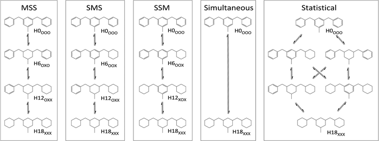
Assuming that species with partially hydrogenated rings and regioisomers can be neglected, up to 6 DBT species may occur during the hydrogenation progress from H0-DBT to H18-DBT. Close examination reveals that H18-DBT can be reached via five different reaction pathways (see Fig. 1). Note that all depicted Hx-DBT structures stand for the different possible regioisomers (different relative positions of the benzyl groups vs. the methyl substituent at the central aromatic ring). For clarity only one regioisomer per DBT species is shown in Fig. 1. The first three reaction pathways (MSS, SMS and SSM) exhibit different hydrogenation preferences for the three aromatic rings of H0-DBT. While the simultaneous reaction path has a lack of intermediates, the statistical path exhibits no ring preference in the hydrogenation process.Estimation of chemical shifts
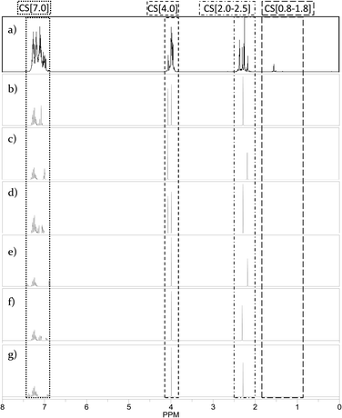
In 1H NMR, hydrogen atoms surrounded by different chemical functionalities show different shifts. According to the various Hx-DBT species formed during the hydrogenation process of H0-DBT (see Fig. 1), the corresponding chemical shifts move from the aromatic regime over the mixed aromatic/aliphatic regime to the purely aliphatic regime.Using the ChemBioDraw25,26 software, 1H NMR spectra of all structural isomers of each Hx-DBT species were predicted in order to define the respective ranges for signal integration. Four different ranges representing different types of hydrogen atoms can be distinguished for the H0-DBT hydrogenation process. As an example, a single-side-ring hydrogenated H6-DBTOOX molecule is shown together with the corresponding NMR spectrum and chemical shifts in Fig. 2. In addition, the predicted 1H NMR spectra of all H0-DBT isomers are shown in Fig. 2 together with the respective measured H0-DBT sample. For all regioisomers, the hydrogen atoms with different chemical shifts can directly be associated to the assigned chemical shift ranges shown in Table 1.
Integration of the four shift ranges and calculation of the fractions according to eqn (1)–(4) have been carried out to determine the fractions of the different types of hydrogen atoms in the respective Hx-DBT samples. According to eqn (5), the sum of all fractions for the different types of hydrogen atoms is 1. Thus, if three fractions are known, the fourth can be calculated according to eqn (5). For this study, the fractions of %CS[7.0], %CS[4.0] and %CS[0.8–1.8] have been determined from the NMR spectra and were used for data evaluation and interpretation.
 | (1) |
 | (2) |
 | (3) |
 | (4) |
| %CS[7.0] + %CS[4.0] + %CS[2.0–2.5] + %CS[0.8–1.8] = 1 | (5) |
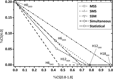
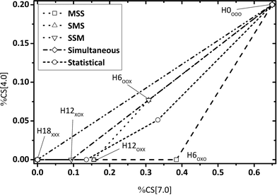
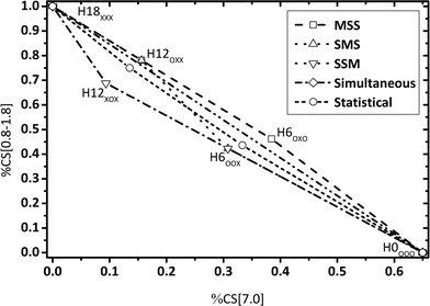
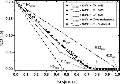
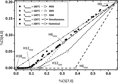
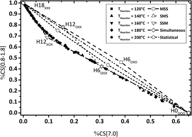
The fractions of the chosen chemical shift integrals were calculated for all Hx-DBT species and are shown in Table 2. Pairing two of the three chemical shift fractions leads to three different plots, showing the characteristic fractions of 1H NMR shifts for the respective reaction paths from Fig. 1. These predictions are displayed in Fig. 3–5.
Some aspects should be highlighted here to better understand Fig. 3–5:
• Simultaneous H0-DBT hydrogenation exhibits only two species according to Fig. 1. The progress for statistical hydrogenation has been calculated by taking into account a one-third chance of middle ring and a two-thirds chance of side ring hydrogenation according to the share of hydrogen to be transferred to these two different positions.
• Hydrogen atoms at the methylene bridges without any aromatic environment exhibit no signal at the CS[4.0] regime. Thus, hydrogenation preference for the middle ring of DBT shows a steeper decrease in CS[4.0] signals compared to any pathway preferring side-ring hydrogenation in the plots of Fig. 3 and 4.
• The hydrogenation with side-ring preference shows the flattest slope between H0 and H12 species in the plot in Fig. 5 as the number of aromatic hydrogen atoms being converted to aliphatic hydrogens through side ring saturation is higher compared to the middle ring hydrogenation.
Evaluation of the potential reaction path “simultaneous”
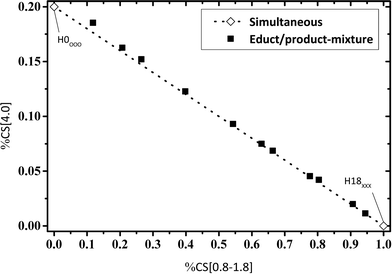
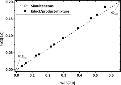
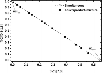
For an estimated “simultaneous” reaction pathway, the reaction mixture consists of a mixture of H0-DBT and H18-DBT as no intermediate hydrogenation products (e.g. H6-DBT or H12-DBT) are formed in this mechanism. To check this option, artificial reaction mixtures were prepared by mixing eleven different fractions of H0-DBT and H18-DBT and these mixtures were measured by 1H NMR. Ratios of chemical shift integrals are plotted in Fig. 6–8 for these mixtures to compare the fractions of chemical shifts obtained in catalytic hydrogenation experiments with the expected trend for such a simultaneous hydrogenation.Reaction path of the H0-DBT hydrogenation
By evaluating the fractions of chemical shift integrals of samples taken during a catalytic H0-DBT hydrogenation experiment, the appearance of these fractions in the NMR spectra are obviously not influenced by the reaction temperature, as shown in Fig. 9–11. This reveals that in the investigated temperature range between 120 and 200 °C the applied Ru on Al2O3 catalyst hydrogenates H0-DBT in the same order of aromatic rings. Furthermore, based on the result in Fig. 9 the reaction paths following the MSS hydrogenation order as well as the Simultaneous and Statistical pathway can be excluded. Simply, the calculated ratios of CS[4.0] vs. CS[0.8–1.8] as shown in Fig. 9 are too far off the experimental values measured for the real hydrogenation process. Taking additionally Fig. 10 into account, the reaction path SMS becomes very unlikely, while the experimental data match particularly well the reaction path SSM.The same conclusion of a strongly preferred SSM reaction path is also confirmed by Fig. 11 where the share of bridging CH2 neighbored by fully hydrogenated cyclohexyl groups is plotted against the share of aromatic protons.
Concerning the revealed SSM pathway, there exist three different options for the pathway to proceed as shown in Fig. 12. All steps may happen in sequence resulting in a three-step pathway or two of the respective steps may happen simultaneously. [SS]M refers to simultaneous hydrogenation of both side-rings as the first step and the middle-ring hydrogenation as the second step, whereas S[SM] represents a single side-ring hydrogenation as the first step and simultaneous side-ring and middle-ring hydrogenation as the second step. Thus, pathway [SS]M contains no H6-DBTXOO and pathway S[SM] contains no H12-DBTXOX. NMR results reveal that H12-DBTXOX must exist during the hydrogenation process due to the fact that in all chemical shift integral fractions of Fig. 9–13. H12XOX is confirmed by experimental data. Lacking of H12XOX would lead to a linear connection line between H6XOO and H18XXX. Hence S[SM] can be excluded.
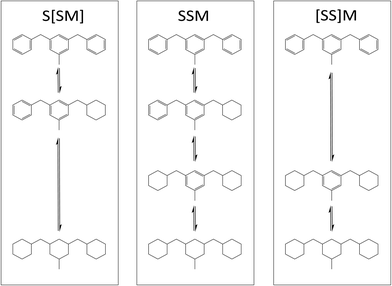 | ||
| Fig. 12 Possible reaction pathways with side-ring preference: three-step reaction SSM and two-step reactions S[SM] and [SS]M. | ||
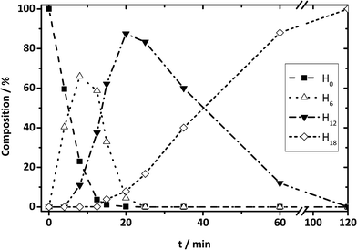 | ||
| Fig. 13 DBT species from HPLC results: composition change during hydrogenation reaction for H0-DBT species to H6-, H12-, and H18-DBT species as a function of time. | ||
On the contrary, NMR results are not conclusive to exclude either [SS]M or SSM, because in both cases the hydrogenation progress goes from H0OOO to H12XOXvia H6OOX. Since mixtures of H0OOO and H12XOX can also represent H6XOO, NMR experimental data are not sufficient here for the final discrimination. Therefore, HPLC investigations of Hx-DBT reaction mixtures were also performed. According to the mass percentage of all Hx-DBT species plotted over hydrogenation time shown in Fig. 13, the three-step SSM reaction is predominant due to the presence of H6 and H12 species. In addition, the main fraction of H18 species emerges when H12 accounts for ∼90 wt%, indicating that middle ring hydrogenation only starts when most of the side rings are saturated. Accordingly, the combination of NMR spectroscopy and HPLC reveals unambiguously an SSM hydrogenation sequence with three independent hydrogenation steps.
Conclusions
In this contribution we report a detailed analysis of the catalytic hydrogenation of dibenzyltoluene on a Ru on Al2O3 catalyst using 1H NMR spectroscopy and HPLC. The reaction is of high relevance in the context of using the dibenzyltoluene (H0-DBT)/perhydrodibenzyltoluene (H18-DBT) pair as a liquid organic hydrogen carrier (LOHC) system.It has been found that in the studied parameter range (T = 120–200 °C, 50 bar hydrogen) the reaction proceeds with a very high preference in a way that first the two side phenyl rings and last the middle phenyl ring are hydrogenated. This new mechanistic insight may help to interpret kinetic results from the H0-DBT hydrogenation and to understand macrokinetic effects with the applied porous catalyst system. Moreover, the methodology presented is suitable to compare different reaction conditions and catalyst materials with regard to the sequence of the hydrogenation pathway. Such insight may help to identify mechanistically different H0-DBT hydrogenation catalysts in the course of further optimization studies of the H0-DBT catalyst. It is an interesting option, for example, to combine within the hydrogenation catalyst bed layers of different catalysts. Based on the results presented here, Ru on Al2O3 appears very suitable for fast side phenyl ring hydrogenation. For finishing the final middle ring hydrogenation a make-up catalyst layer with a different catalyst material could be more suitable, as it has been found that middle ring hydrogenation with Ru on Al2O3 is a slow step that only sets in when almost every LOHC has been converted to the H12-DBT state. Most remarkably, no side products outside the intended reaction pathway from H0-DBT towards H18-DBT have been detected at least by NMR. This confirms that hydrogen storage in the LOHC system H0-DBT/H18-DBT is indeed a very selective process making this system highly suitable for repeated hydrogen storage in reversible hydrogenation/dehydrogenation cycles.
Acknowledgements
The authors acknowledge financial support by the application center VerTec in Fürth, the Bavarian Hydrogen Center, the Energie Campus Nürnberg and the Erlangen Excellence Cluster “Engineering of Advanced Materials”.Notes and references
- (a) D. Teichmann, W. Arlt, P. Wasserscheid and R. Freymann, Energy Environ. Sci., 2011, 4, 2767–2773 RSC; (b) K. Müller, K. Stark, V. N. Emel'yanenko, M. A. Varfolomeev, D. H. Zeitsai, E. Shoifetm, C. Schick, S. P. Verevkin and W. Arlt, Ind. Eng. Chem. Res., 2015, 54, 7967–7976 CrossRef; (c) D. Teichmann, K. Stark, K. Müller, G. Zöttl, P. Wasserscheid and W. Arlt, Energy Environ. Sci., 2012, 5, 9044–9054 RSC.
- D. Teichmann, W. Arlt, P. Wasserscheid and R. Freymann, Energy Environ. Sci., 2011, 4, 2767–2773 Search PubMed.
- K. M. Eblagon, K. Tam and S. C. E. Tsang, Energy Environ. Sci., 2012, 5, 8621–8630 Search PubMed.
- F. Sotoodeh, B. J. M. Huber and K. J. Smith, Appl. Catal., A, 2012, 419–420, 67–72 CrossRef CAS.
- M. Markiewicz, Y. Q. Zhang, A. Bösmann, N. Brückner, J. Thoming, P. Wasserscheid and S. Stolte, Energy Environ. Sci., 2015, 8, 1035–1045 Search PubMed.
- D. Teichmann, W. Arlt and P. Wasserscheid, Int. J. Hydrogen Energy, 2012, 37, 18118–18132 CrossRef CAS.
- D. Geburtig, P. Preuster, A. Bösmann, K. Müller and P. Wasserscheid, Chemical utilization of hydrogen from fluctuating energy sources – Catalytic transfer hydrogenation from charged Liquid Organic Hydrogen Carrier systems, Int. J. Hydrogen Energy, 2016, 41(2), 1010–1017 CrossRef CAS.
- A. F. Dalebrook, W. Gan, M. Grasemann, S. Moret and G. Laurenczy, Chem. Commun., 2013, 49, 8735–8751 RSC.
- N. Brückner, K. Obesser, A. Bösmann, D. Teichmann, W. Arlt, J. Dungs and P. Wasserscheid, ChemSusChem, 2014, 7, 229–235 CrossRef PubMed.
- K. Müller, K. Stark, V. N. Emelyanenko, M. A. Varfolomeev, D. H. Zaitsau, E. Shoifet, C. Schick, S. P. Verevkin and W. Arlt, Ind. Eng. Chem. Res., 2015, 54, 7967–7976 CrossRef.
- Safety data sheet “Marlotherm SH”, (http://217.115.131.139/cms/ext_modules/schmieren/php/ausgabe_datenblaetter.php?pfad=2.13&dateiname=13.3.S.pdf) Search PubMed.
- P. P. Fu, H. M. Lee and R. G. Harvey, J. Org. Chem., 1980, 45, 2797–2803 CrossRef CAS.
- E. Bresó-Femenia, B. Chaudret and S. Castillón, Catal. Sci. Technol., 2015, 5, 2741–2751 Search PubMed.
- A. T. Lapinas, M. T. Klein, B. C. Gates, A. Maoris and J. E. Lyons, Ind. Eng. Chem. Res., 1991, 30, 42–50 CrossRef CAS.
- M. T. Klein, S. C. Korre, C. J. Read and C. L. Russell, In Hydrocracking of model polynuclear aromatics: Reaction pathways, kinetics, and structure/reactivity correlations, Am. Chem. Soc., 1993, 1871–1877 Search PubMed.
- C. E. Crompton, The Catalytic Hydrogenation of Polynuclear Hydrocarbons: Part A: Polyphenyl Systems. Part B: Condensed Ring Systems, University of Tennessee, 1949 Search PubMed.
- D. A. Scola, J. S. Adams, C. I. Tewksbury and R. J. Wineman, J. Org. Chem., 1965, 30, 384–388 CrossRef CAS.
- M. H. Moh, T. S. Tang and G. H. Tan, J. Am. Oil Chem. Soc., 2000, 77, 1077–1082 CrossRef CAS.
- M. H. Moh, T. S. Tang and G. H. Tan, J. Am. Oil Chem. Soc., 2002, 79, 379–382 CrossRef CAS.
- M. H. Moh, T. S. Tang and G. H. Tan, J. Am. Oil Chem. Soc., 2005, 82, 233–236 CrossRef CAS.
- D. B. Min and J. Wen, J. Am. Oil Chem. Soc., 1982, 59, 278–279 CrossRef CAS.
- M. A. Chel'tsova, A. D. Petrov, E. D. Lubuzh and T. E. Eremeeva, Bull. Acad. Sci. USSR, Div. Chem. Sci., 1965, 14, 107–115 CrossRef.
- M. Hesse, H. Meier and B. Zeeh, Spektroskopische Methoden in der organischen Chemie, Thieme, 2005 Search PubMed.
- H. Günther, NMR Spectroscopy: Basic Principles, Concepts and Applications in Chemistry, Wiley, 2013 Search PubMed.
- E. Pretsch, P. Bühlmann and M. Badertscher, in Structure Determination of Organic Compounds, Springer, Berlin Heidelberg, 2009, ch. 5, pp. 1–86, DOI:10.1007/978-3-540-93810-1_5.
- R. B. Schaller, M. E. Munk and E. Pretsch, J. Chem. Inf. Comput. Sci., 1996, 36, 239–243 CrossRef CAS.
Footnote |
| † Electronic supplementary information (ESI) available. See DOI: 10.1039/c5re00080g |
| This journal is © The Royal Society of Chemistry 2016 |

