Rotation induced by uniform and non-uniform magnetic fields in a conducting fluid carrying an electric current

R. Shirsavarab, M. Nasiria, A. Amjadib, A. Nejatic, S. O. Sobhanibd and Mehdi Habibi*ef
aDepartment of Physics, Faculty of Science, University of Zanjan, Zanjan, Iran
bDepartment of Physics, Sharif University of Technology, Tehran, Iran
cPhysikalisches Institut and Bethe Center for Theoretical Physics, Universität Bonn, Germany
dDepartment of Energy Engineering, Sharif University of Technology, Tehran, Iran
eCondensed Matter National Laboratory, IPM, Tehran, Iran
fInstitute of Physics, University of Amsterdam, Science Park 904, Amsterdam, The Netherlands. E-mail: m.habibi@uva.nl

Received 30th September 2016 , Accepted 24th November 2016

First published on 24th November 2016


Abstract

We study the dynamics of a conducting fluid carrying (i) a uniform current in the presence of a non-uniform magnetic field or (ii) carrying a non-uniform current in the presence of a uniform magnetic field, using particle image velocimetry (PIV). Our results show that the average angular velocity of the induced rotation has a power-law dependence on the electric current passing through the fluid with an exponent ≈2/3, in excellent agreement with our simulation results, for the same system. To explain the experimental observations we explore all possibilities for inducing rotation in a fluid carrying an electric current. Our theoretical discussion indicates two scenarios wherein applying electric/magnetic field on a current-carrying fluid produces rotational vortices: (i) applying a non-uniform magnetic field in the presence of an electric current and, (ii) applying a magnetic field in the presence of a non-uniform electric current. These two theoretical scenarios for inducing rotation by applying external fields agree well with our experimental observations and simulation results.

I. Introduction

The prospect of manipulating fluid flow by electric and magnetic fields with its various applications in biology, chemistry, microfluidics and drug delivery systems, has been the motivation for a wide range of studies on electrically and magnetically driven fluid flow. Interaction of electric fields with fluids was first studied by Melcher et al.,1,2 and electro-hydrodynamical instabilities were investigated by Taylor3 and Saville.4 Electric fields have long been utilized for electro-phoretic separations, electro-osmotic pumping, electro-wetting and dielectro-phoretic trapping.5–9 Related experimental studies have also been performed by Ramos et al.10,11 on control and manipulation of nano/micro particles in a fluid using electric fields. The case of suspended liquid films has also attracted some recent attention. Shirsavar et al. studied soap film flow by non-uniform alternating electric field.12 Faetti et al.13,14 observed formation of vortices by electric currents in a suspended liquid crystal film. Morris et al.15,16 suggested that it is the electric charges accumulated on the surface of suspended films that produce such instabilities. Amjadi et al.17–19 proposed a method for controlling the rotational flow on thin suspended liquid films demonstrating that a simultaneous application of an electric field and an electric current produces controllable rotations in a suspended liquid film. Such an instability has been studied theoretically by Liu et al.20,21 and Nasiri et al.22 and the rotation mechanism was explained by Feiz et al. using a thin film electro-convection model.23 It has been shown recently that this method is also capable of inducing controlled rotations in the fluid bulk with free surfaces.24

Applying a magnetic field in the presence of an electric current produces a Lorentz force acting on the fluid and results in fluid movement. This magneto-hydrodynamic method of inducing flow in a conducting fluid has a wide range of applications in microfluidics and microchemistry and has been studied by different groups for various purposes.5,25–29 Along the same direction, in this paper, we extend our previous study (electrically-induced rotation17–19) by investigating rotations induced by uniform and non-uniform magnetic fields in conducting fluids carrying electric current. We look for different configurations in which an applied electric/magnetic field in the presence of an electric current results in generation of vorticity in an incompressible fluid. We assume steady-state conditions and time-independent electric and magnetic fields as the external fields, and provide a qualitative theoretical framework to explore all possibilities in which electric/magnetic fields, in the presence of electric current passing through the fluid, are able to induce rotating flow. Our experimental, simulation and theoretical results indicate that the flow velocity can be adjusted by tuning the direction and strength of the magnetic field and the electric current. The experimental results and theoretical framework presented in this work will be useful for developing novel methods of fluid flow manipulation with applications in many important areas including biology and chemistry30,31 and small-scale industrial applications, e.g. ‘lab-on-a-chip’ devices.32

II. Experimental procedure

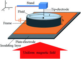
Two different setups are designed to study fluid rotation induced by magnetic fields. In the first setup, a rectangular frame is used in order to apply a non-uniform magnetic field (B) and a uniform DC electric current (J) to the fluid (Fig. 1a), while in the second setup, a uniform magnetic field along with a non-uniform current is applied to the fluid by using a circular frame (Fig. 2a). In both cases, the electrical conductivity of distilled water (used as working fluid) is increased to 13.37 ms cm−1 by adding sodium chloride (NaCl). Passing electric currents in the presence of magnetic field in both setups induces rotations in the fluid bulks. To detect the rotation and determine the velocity profile, tracer particles with average size of 50 μm were poured on the air–water interface. The concentration of the particles is low enough to ignore the effect of the tracer on the velocity field. The velocity field is obtained by taking movies and photographs from the tracer particles on the free surface of the fluid and using particle image velocimetry (PIV). Finally, the average angular velocity of the surface of the fluid can be obtained either by following a tracer particle at a specific distance from the rotation center or by PIV measurements. Thickness of the fluid layer in both setups is about 4 mm. Details of the two experimental setups are described as follow.
image file: c6ra24346k-f1.tif
Fig. 1 (a) Schematic of the first setup (cubic); a uniform current passing through a fluid bulk in the presence of a non-uniform magnetic field. (b) Top view of the experimental setup. (c) Velocity profile of the fluid surface obtained by PIV. (d) Simulation results for the velocity vector field at the liquid/air interface in the first setup.

image file: c6ra24346k-f2.tif
Fig. 2 (a) Schematic of the second setup (circular); a non-uniform current passing through a fluid bulk in the presence of a uniform magnetic field. (b) Top view of the experimental setup. (c) Velocity profile of the fluid surface obtained by PIV. (d) Simulation results for the velocity vector field at the liquid/air interface.

1. Non-uniform magnetic field and uniform electric current

The first setup consists of a rectangular cell (xyz: 1 × 1 × 0.4 cm3) with two identical plate electrodes on its opposite sides. A uniform electric current passes through the fluid while a non-uniform magnetic field is applied to the cell (Fig. 1a). To produce the non-uniform magnetic field, we use two cubic magnets as shown in the figure. We can change the maximum strength of the magnetic field by changing the magnets. Two different combinations of magnets are used with maximum strengths (Bmax) of 0.2 ± 0.01 T and 0.3 ± 0.01 T. To investigate the effect of electric current on the velocity field we increase the applied electric current from 0.3 mA to 10 mA by increasing the electric potential difference between the electrodes.

2. Uniform magnetic field and non-uniform electric current

The second setup consists of a cylindrical cell (radius = 7 mm, height = 4 mm) with a plate electrode at the bottom and a tip electrode on the top (Fig. 2). Using this setup a current gradient is generated through the fluid. We apply an approximately uniform magnetic field in the vertical (z) direction by using a large magnet at the bottom. The setup is designed in a way that the magnet and the plate electrode at the bottom are separated by a thin insulating layer. The electric current passing through the fluid is changed from 2 mA to 12 mA for two different uniform magnetic fields with maximum strengths of 0.2 ± 0.01 T and 0.3 ± 0.01 T.

III. Experimental results

The velocity fields obtained by PIV technique for typical experiments are shown in Fig. 1c and 2c. For each applied electric current, velocity field and average angular velocity of the fluid at the free surface is measured. The average angular velocity of the fluid is plotted as a function of the electric current in logarithmic scale in Fig. 3. These data indicate that the average angular velocity has a power-law dependence on the electric current with an exponent ≈2/3. The exponent is roughly independent of the magnitude of the magnetic field and the geometry and configuration of the setups. However, as it is clearly shown in Fig. 3, a higher applied magnetic field results in a slightly larger angular velocity in the fluid which implies that a higher field produces stronger torques on the fluid, and consequently leads to higher angular velocities. It is worth mentioning that the presence of the free surface is not essential for the effects observed here, although in the both setups we have free surfaces. To check that, a simple experiment is performed by the second setup while the free surface is covered with a glass plate with a tip electrode in its middle. The rotation is induced in the same direction compering to the system with the free surface, however the frequency of rotation is lower for the same experimental parameters, probably due to no-slip boundary condition at the solid surfaces.
image file: c6ra24346k-f3.tif
Fig. 3 Average angular velocity as a function of electric current passing through the fluid in logarithmic scale for both setups and two different maximum strengths of the magnetic field. Experimental and simulation results are shown by empty and filled symbols respectively. Black and red symbols represent the results for Bmax = 0.3 ± 0.01 T and Bmax = 0.2 ± 0.01 T, respectively, while squares (circles) are related to the cubic (circular) setup. A dashed line with slope 2/3 is shown on the plot as a guide for the eye. Best fits to the experimental data give exponents 0.59 for Bmax = 0.2 T and 0.64 for Bmax = 0.3 T in the first setup (cubic), and 0.68 for Bmax = 0.2 T and 0.64 for Bmax = 0.3 T in the second one (circular).

IV. Theory and discussion

For incompressible fluids, the velocity field u(u, v, w) is governed by the Navier–Stokes equation,
 
image file: c6ra24346k-t1.tif(1)
 
∇·u = 0, (2)
where ρ and η are mass density and viscosity of the fluid, respectively, P is the pressure and f represents body force density applied to the fluid.

As a local measure of rotation, vorticity, defined as ω = ∇ × u, is one of the major dynamical properties of a fluid. The evolution of vorticity can be derived directly by taking the curl of the Navier–Stokes equation,

 
image file: c6ra24346k-t2.tif(3)
where ν is the kinematic viscosity and the fluid density (ρ) is assumed to be spatially homogeneous. Eqn (3) indicates that in a time-independent flow, a force for which ∇ × f ≠ 0, can generate vorticity in the fluid bulk.

In our experiments, we deal with electric/magnetic forces (fe or fm). The electric force applied on a polarized isotropic fluid in an electric field E, at temperature T is given as

 
image file: c6ra24346k-t3.tif(4)
where ε is the fluid permittivity. In this relation it is supposed that the electric polarization of the liquid is a linear function of the electric field E.33 The first term of the eqn (4) is the Coulomb force on the free charges, the second term is the dielectric force while the last term is the electrostriction33 force density associated with volumetric change in the material.

The magnetic force on a conductive fluid subject to a magnetic field is given by

 
fm = J × B, (5)
where J and B are electric current density and magnetic field, respectively. For a moving conductive fluid subjected to electric and magnetic fields, the current density reads
 
J = σE + σu × B, (6)
where σ is the conductivity of the liquid and the charge diffusivity effects are neglected due to small diffusion coefficient of the ions. Here the first term represents the conduction current caused by external electric fields and the second term is due to the motion of a conductor through a magnetic field.

Considering steady-state conditions for a homogeneous fluid and taking the curl of the body force we obtain

 
∇ × f = ∇ × fe + ∇ × fm = −(J·∇)B + (B·∇)J. (7)

This equation (eqn (7)) explicitly shows that there are two terms associated with generation of vorticity and hence, suggests two distinct methods of inducing rotation in the fluid. Non-uniform magnetic field in the presence of any current (first term) or any magnetic field in the presence of a non-uniform current (second term) will generate vorticity in the fluid. These two terms can explain our experimental observations for the two setups. In our experiments to simplify our systems and avoid further complexities, we have utilized only uniform current and uniform magnetic field in the first and second setup respectively. The observed rotation in the first setup due to applying a non-uniform magnetic field in the presence of a uniform current is described by the first term of the eqn (7). In the second experimental setup, a uniform magnetic field applied in the vertical direction (z), in the presence of a non-uniform current between the tip and the plate electrodes produces rotation as described by the second term of the eqn (7).

To determine the sense of the induced rotations, we need to consider the magnetic force exerted on the electric current (J × Bext); direction of this vector product is the same as the sense of rotation observed in the experiments. As shown in Fig. 3, the angular velocity of the fluid increases with increasing the electric current and the magnetic field, in agreement with eqn (7). However, our experimental results show a power-law behavior for the average rotational velocity as a function of the passing current with an exponent which is probably the result of nonlinear coupling between Navier–Stokes equation and electromagnetic fields.

V. Simulation

In this section we use the finite element method (FEM) to solve the governing equations with the help of COMSOL Multiphysics Modeling software.34 The governing equations for our problem are described in Section 4 and the related geometries for the simulation are based on the experimental setups explained in the Section II.

The electric potential (ϕ) inside the fluid obeys the first Maxwell's equation:

 
∇·(σϕ) = 0 (8)
where free charges are neglected due to electro-neutrality assumption far from the electrodes. We further assume a constant conductivity for the fluid. The boundary conditions for the above equation are: (1) given electric current at one of the electrodes and constant potential at the other electrode, (2) zero normal current at the remaining boundaries.

In our experiments, image file: c6ra24346k-t4.tif, so the second term in eqn (6) can be neglected and the current density of the moving fluid can be approximately described with Ohm's law,

 
JσE. (9)

A potential difference between the electrodes generates a nonuniform (uniform) electric current density in cylindrical (cubic) geometries. Once we obtain the electric current, we can calculate the magnetic force using J × B. The definition of external magnetic field is the same as that shown in Fig. 1a or 2a.

The fluid motion is governed by eqn (2) where we use ρ = 1000 kg m−3 and η = 0.001 Pa s for distilled water at ambient pressure.35 According to eqn (4) and (5) we define the body force as

 
f = fe + fm + ρg (10)
where the third term is the gravitational body force. The gravitational force and the last term of fe in eqn (4) are the gradient of a scalar and can be incorporated into a redefined pressure for an incompressible fluid. We neglect the Coulomb force on the free charges regarding the electro-neutrality assumption; therefore, the body force simply reads
 
ffm = J × BJ × Bext. (11)

The proposed boundary conditions for the hydrodynamic equations are: (1) zero velocity perpendicular to the liquid/air interface (u·[n with combining circumflex] = 0) where [n with combining circumflex] is the normal vector of the interface and (2) no-slip boundary condition at the remaining boundaries.

Fig. 1d and 2d depict the simulation results for the vector field (u, v, w = 0) at the liquid/air interface for both geometries. The results are in qualitative agreement with that shown in Fig. 1c and 2c. To quantitatively compare the simulation with experiments we have plotted the average angular velocity of the flow versus current passing through the liquid for different external magnetic fields in Fig. 3. As it is clearly shown in Fig. 3, the simulation results (filled symbols) for the average angular velocity show the same power-law dependency as the experimental data (open symbols). The exponent is independent of the magnitude of the magnetic fields, and configuration of the setups in agreement with the experiments. Similar to our experimental observations a higher applied magnetic field results in a slightly larger angular velocity in the fluid. The agreement between simulation and experimental data for the circular geometry is perfect, although experimental results for the cubic setup are slightly below the simulation prediction for the same system. This could be due to the complexity of the boundaries (sharp angels) in the cubic setup which can cause generation of complex vortices at the corners. Another possible explanation for this small difference between simulation and experiment could be the difficulty in defining the magnetic field near the gap separating the two magnets in simulation of the cubic setup.

VI. Conclusion

We studied the rotation induced by an external magnetic field on a conductive fluid carrying electric current in two configurations. In the first case, a uniform electric current passes through the fluid in the presence of a non-uniform external magnetic field while in the second setup, a non-uniform current passes through the fluid with a uniform external magnetic field. In both cases, applying a current in the presence of the magnetic field induces rotation in the fluid bulk. Our experimental results indicate that the average angular velocity increases with increasing the electric current as a power-law with an exponent ≈2/3, in excellent agreement with our simulation results.

To support the experimental observations, a qualitative theoretical framework is provided based on using Maxwell and vorticity equations for an incompressible viscous fluid. By neglecting the electric and magnetic polarizations of the fluid in the first approximation, and simplifying the body force, two possibilities are suggested for electromagnetically induced rotation in a conducting fluid: first, applying an external non-uniform magnetic field in the presence of an electric current, second, applying an external magnetic field in the presence of a non-uniform electric current. These two scenarios have been reproduced in the experiments. Our theoretical discussion also predicts the possibility of increasing the average rotational velocity by increasing the current or strength of the external field, in agreement with our experimental observations and simulation results.

The experimental results, quantitative simulation results and qualitative theoretical framework presented here can provide a basis for designing dynamic micro-pumps based on novel electro-hydrodynamic and magneto-hydrodynamic techniques. Such devices do not require any moving parts and are suitable for any conducting fluid and could have various applications in microfluidics from micro-mixer and micro-pumps for biological or chemical applications30,31 to drug delivery devices,36 or more generally, in the fast-growing ‘lab-on-a-chip’ technology.

Acknowledgements

The experimental part of this work was performed in Medical Physics and Laser Lab supported by Sharif University Applied Physics Research Center. We would like to acknowledge the fruitful discussions with Prof. M. Zahn and Prof. M. R. Ejtehadi and also, the technical help from Dr M. R. Mozaffari and M. K. Zand. MH thanks Prof. S. Morris for his invaluable discussions and acknowledges support from VIDI fellowship from NWO.

References

  1. J. R. Melcher, Phys. Fluids, 1961, 4, 1348 CrossRef.
  2. J. R. Melcher and C. V. Smith, Phys. Fluids, 1969, 12, 778 CrossRef.
  3. G. Taylor, Proc. R. Soc. London, Ser. A, 1966, 291, 159 CrossRef.
  4. D. A. Saville, Annu. Rev. Fluid Mech., 1997, 29, 27 CrossRef.
  5. N. Pamme, Lab Chip, 2006, 6, 24 RSC.
  6. T. Vilkner, D. Janasek and A. Manz, Anal. Chem., 2004, 76, 3373 CrossRef CAS PubMed.
  7. A. Javadi, M. Habibi, F. S. Taheri, S. Moulinet and D. Bonn, Sci. Rep., 2013, 3, 1412 Search PubMed.
  8. D. R. Reyes, D. Iossifidis, P. A. Auroux and A. Manz, Anal. Chem., 2002, 74, 2623 CrossRef CAS PubMed.
  9. P. A. Auroux, D. Iossifidis, D. R. Reyes and A. Manz, Anal. Chem., 2002, 74, 2637 CrossRef CAS PubMed.
  10. A. Ramos, H. Morgan, N. G. Green and A. Castellanos, J. Phys. D: Appl. Phys., 1999, 31, 2338 CrossRef.
  11. A. Ramos, H. Morgan, N. G. Green and A. Castellanos, J. Colloid Interface Sci., 1999, 217, 420 CrossRef CAS PubMed.
  12. R. Shirsavar, A. Ramos, A. Amjadi, J. Taherinia, M. Mashhadi and A. Nejati, J. Electrost., 2015, 73, 112 CrossRef.
  13. S. Faetti, L. Fronzoni and P. A. Rolla, J. Chem. Phys., 1983, 79, 5054 CrossRef CAS.
  14. S. Faetti, L. Fronzoni and P. A. Rolla, J. Phys. Colloq., 1979, 40, 497 CrossRef.
  15. S. W. Morris, J. R. de Bruyn and A. May, Phys. Rev. Lett., 1990, 65, 2378 CrossRef CAS PubMed.
  16. Z. A. Daya, S. W. Morris and J. R. de Bruyn, Phys. Rev. E: Stat. Phys., Plasmas, Fluids, Relat. Interdiscip. Top., 1997, 55, 2682 CrossRef CAS.
  17. A. Amjadi, R. Shirsavar, N. H. Radja and M. R. Ejtehadi, Microfluid. Nanofluid., 2009, 6, 711 CrossRef CAS.
  18. R. Shirsavar, A. Amjadi, A. Tonddast-Navaei and M. R. Ejtehadi, Exp. Fluids, 2011, 50, 419 CrossRef CAS.
  19. R. Shirsavar, A. Amjadi, M. R. Ejtehadi, M. R. Mozaffari and M. S. Feiz, Microfluid. Nanofluid., 2012, 13, 83 CrossRef CAS.
  20. Z.-Q. Liu, G.-C. Zhang, Y.-J. Li and S.-R. Jiang, Phys. Rev. E: Stat., Nonlinear, Soft Matter Phys., 2012, 85, 036314 CrossRef PubMed.
  21. Z.-Q. Liu, Y.-J. Li, K.-Y. Gan, S.-R. Jiang and G.-C. Zhang, Microfluid. Nanofluid., 2013, 14, 319 CrossRef CAS.
  22. M. Nasiri, R. Shirsavar, T. Saghaei and A. Ramos, Microfluid. Nanofluid., 2015, 19, 133 CrossRef.
  23. M. Feiz, R. Namin and A. Amjadi, Phys. Rev. E: Stat., Nonlinear, Soft Matter Phys., 2015, 92, 033002 CrossRef CAS PubMed.
  24. T. Saghaei, A. Moradi, R. Shirsavar and M. Habibi, Appl. Phys. Lett., 2015, 106, 053506 Search PubMed.
  25. J. Jang and S. S. Lee, Sens. Actuators, A, 2000, 80, 84 CrossRef CAS.
  26. J. C. T. Eijkel, C. Dalton, C. J. Hayden, J. P. H. Burt and A. Manz, Sens. Actuators, B, 2003, 92, 215 CrossRef CAS.
  27. M. C. Weston, M. D. Gerner and I. Fritsch, Anal. Chem., 2010, 82, 3411 CrossRef CAS PubMed.
  28. J. West, B. Karamata, B. Lillis, J. P. Gleeson, J. Alderman, J. K. Collins, W. Lane, A. Mathewson and H. Berney, Lab Chip, 2002, 2, 224 RSC.
  29. A. Homsy, J. C. T. Eijkel, A. van den Berg, F. Lucklum, E. Verpoorte and N. F. de Rooij, Lab Chip, 2005, 5, 466 RSC.
  30. F. Amirouche, Y. Zhou and T. Johnson, Microsyst. Technol., 2009, 15, 647 CrossRef CAS.
  31. S. Z. Qian and H. H. Bau, Mech. Res. Commun., 2009, 36, 10 CrossRef PubMed.
  32. D. J. Laser and J. G. Santiago, J. Micromech. Microeng., 2004, 14, R35 CrossRef.
  33. Electrokinetics and Electrohydrodynamics in Microsystems, ed. A. Ramos, Springer-Verlag, Wien, 2011 Search PubMed.
  34. COMSOL Multiphysics Modeling Software, accessed 30 Apr. 2016, http://www.comsol.com Search PubMed.
  35. M. S. Kestin Joseph and W. A. Wakeham, J. Phys. Chem. Ref. Data, 1978, 7, 941 CrossRef.
  36. A. Nisar, N. Afzulpurkar, B. Mahaisavariya and A. Tuantranont, Sens. Actuators, B, 2008, 130, 917 CrossRef CAS.

This journal is © The Royal Society of Chemistry 2016
Click here to see how this site uses Cookies. View our privacy policy here.