Cauliflower-like Ni/NiO and NiO architectures transformed from nickel alkoxide and their excellent removal of Congo red and Cr(VI) ions from water

Junfeng Zhaoab, Jiachen Zhab, Hongbin Lua, Cheng Yangb, Kou Yanb and Xiangkang Meng*a
aInstitute of Materials Engineering, National Laboratory of Solid State Microstructures, College of Engineering and Applied Sciences, Nanjing University, Jiangsu, P. R. China. E-mail: mengxk@nju.edu.cn
bSchool of Chemistry and Materials Engineering, Changshu Institute of Technology, Changshu, P. R. China

Received 24th September 2016 , Accepted 21st October 2016

First published on 26th October 2016


Abstract

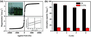
Cauliflower-like nickel alkoxide, Ni/NiO and NiO architectures were synthesized via a reflux route using NaBH4–EG as alkaline precipitant. The as-prepared powders were characterized by XRD, FESEM, TEM, HRTEM, and N2 adsorption/desorption isotherms. The results show that the nickel alkoxide is made up of smooth spherical building blocks with diameters of about 500 nm that aggregate interactively to form whole 3D structures. The Ni/NiO and NiO architectures can be obtained by the direct thermal transformation from nickel alkoxide precursor at 300 °C and 600 °C, respectively, which are assembled by nanoparticles and composed of mesopores and macropore. The as-prepared three samples exhibit excellent performance for the removal of Congo red (CR) and Cr(VI) pollutant from aqueous solutions due to their hierarchical structures and high specific surface areas. The corresponding adsorption process fits well with the pseudo-second-order kinetics model and the Langmuir model. Compared with nickel alkoxide and NiO, Ni/NiO architectures show the highest adsorption performance, with the maximum capacity of 642.37 and 92.52 mg g−1 for CR and Cr(VI), respectively. Further, the easily magnetic separation and reused clearly suggests that the Ni/NiO architectures can be explored as an excellent adsorbent for the removal of organic dye and heavy metal ions from aqueous solutions.


1. Introduction

In the past few decades, inorganic heavy metal ions and organic dyes present in industrial or urban waste water have become one of the most important environmental issues due to their long-term environmental toxicity and short-term public damage.1,2 Up to now, a wide range of technologies, including ion exchange,3,4 chemical adsorption,5,6 precipitation,7,8 and electrochemical processes,9 were used for the removal of pollution from wastewater. Among them, adsorption is one of the most effective and popular methods because of its advantages of high efficiency, ease of operation and low cost.10,11

The new concept and approach for water treatment has been developed with the development of nano science and technology. Various micro/nano-sized metal oxides with well-defined morphology and large specific surface area were studied for application in wastewater treatment. Nickel oxide (NiO), an important p-type wide-bandgap oxide semiconductor, was extensive investigated because of its promising application in catalysis,12 lithium ion batteries,13,14 supercapacitor,15 and gas sensors.16 Recently, considerable research was also committed to the synthesis of various NiO structures for their potential applications in pollution adsorption.17–19 For example, Ai et al. synthesized hierarchical porous NiO architectures by a solvothermal route combining a calcination process, and demonstrated its high performance toward the removal of Congo red (CR) in water.20 Lou et al. utilized a solvothermal method to prepare hierarchical NiO spheres, which exhibited a high adsorption capacity for the CR removal.21 Hu et al. adopted a microwave-assisted aqueous chemical reaction to synthesize NiO architecture, and found to be an effective adsorbent for the removal of CR from wastewater.22 However, some of these adsorbents are difficult to be widely applied in practice, due to high cost, difficult separation and regeneration. Combined with magnetic technique may offer promise for use in the field of wastewater treatment, because it produces no contaminants and can be easily separated by an external magnetic field. Undoubtedly, it is of great important to realize the facile synthesis of magnetic nanostructure adsorbent to optimize their adsorption performance and regeneration capability.

In the present paper, we reported the synthesis of cauliflower-like nickel alkoxide, Ni/NiO and NiO architectures via a facile precipitation route using NaBH4–EG as alkaline precipitant. The as-prepared nickel alkoxide, Ni/NiO and NiO architectures exhibit excellent adsorption capability for removal of Congo red (CR) and Cr(VI) from aqueous solution. The adsorption process was clarified by the adsorption isotherms and kinetics. Furthermore, the Ni/NiO architectures can be easily separated via an external magnetic field and reused, suggesting its potential practical application in water treatment.

2. Experiment

2.1 Materials and method

Analytical grade of Ni(NO3)2·6H2O, NaBH4, ethylene glycol (EG), K2Cr2O7, and Congo red (CR) were purchased from Aladdin Co., (Shanghai, China), and used without any further purification. The synthesis process was modified from the method by Liu et al.23 Typically, 1.2 g NaBH4 was dissolved in 25 mL ethylene glycol, forming NaBH4–EG solution. 1.2 g Ni(NO3)2·6H2O dissolved in 100 mL EG, and added into the above NaBH4–EG solution, to form a green transparent solution. The mixture was kept stirring and refluxed at 190 °C for 1 h. After cooling to room temperature, the green precipitates were collected and washed with deionized water and absolute ethanol for several time, then dried at 80 °C for 24 h. To obtain the Ni/NiO and NiO powders, the dried green product was calcined at 300 °C and 600 °C in air for 3 h, respectively.

2.2 Characterization

The crystal structure was described by X-ray diffraction (XRD, Dmax-2200PC) with CuKα radiation (40 kV, 40 mA). The morphologies were conducted on field emission scanning electron microscope (FE-SEM, Zeiss Sigma) and transmission electron microscopy (TEM, JEM-2100). The surface areas and porosity of the powders were carried out by N2 adsorption–desorption isotherm (AS AP 2020). Magnetization measurement was carried out at room temperature using a vibrating sample magnetometer (VSM, Lakeshore).

2.3 Adsorption equilibrium and kinetic experiment

For the adsorption of CR dye, 100 mg of as-prepared samples were dispersed in 100 mL of CR aqueous solution with different initial concentrations ranging from 100 to 500 mg L−1 (100, 200, 300, 400, and 500 mg L−1) under constant stirring. After the completion of present time intervals, 3 mL of suspension was sucked out and centrifuged for separating the solution with the adsorbent. The residual CR concentration in the solution was determined by a UV-vis instrument (Cary-300, Agilent) at 498 nm.

The heavy metal pollution adsorption studies were performed in a standard solution of Cr(VI). Typically, 100 mg of the as-prepared samples was mixed with 100 mL of aqueous of Cr(VI) with various concentrations (20, 40, 60, 80, 100, 120, 140, and 160 mg L−1). The Cr(VI) concentrations were analyzed by UV-vis instrument at 540 nm.

The adsorption capacity was calculated by eqn (1).

 
image file: c6ra23775d-t1.tif(1)
where C0 is the initial concentration of pollution (mg L−1), qt (mg g−1) is the amount adsorbed per gram of adsorbent at time t (min), Ct is the concentration of pollution at time t of adsorption (mg L−1), V is the initial volume (L) of the pollution solution, and W is the weight of the adsorbent (g).

3. Results and discussion

3.1 Characterizations of the nickel alkoxide

Fig. 1a shows the XRD patterns of the precursor. The characteristic peak at around 10° is a standard pattern for metal alkoxide.24,25 FT-IR investigation was carried out to reveal the organic components and bonding situation of the precursor, as shown in Fig. 1b. The broad band located at 3400 cm−1 is attributed to –OH band. The bands at 2500–3000 cm−1 are corresponded to the C–H stretching mode. All the bands below 2000 cm−1 are ascribed to Ni–O, C–C, C–O, and CH2 groups in the precursor. The presence of these organic groups also confirmed that the as-prepared precursor is nickel alkoxide.
image file: c6ra23775d-f1.tif
Fig. 1 (a) XRD pattern of nickel alkoxide, (b) FTIR spectra of ethylene glycol (EG), NaBH4–EG, and nickel alkoxide.

The morphology of the as-prepared nickel alkoxide was studied by FESEM and TEM. The nickel alkoxide presents cauliflower-like architectures, as shown in Fig. 1a. The TEM image in Fig. 2c reveals that cauliflower-like nickel alkoxide was composed of spherical structures with diameters of about 500 nm. A high magnification image is shown in Fig. 2d, indicating a hierarchical nanostructure. The selected area electron diffraction (SAED) pattern in insert image of Fig. 2d presents concentric diffuse rings, revealing the polycrystalline nature of nickel alkoxide. The special surface area was further investigated by nitrogen adsorption/desorption measurement. According to the IUPAC classification, the isotherm in Fig. 2b can be classified as type IV with a hysteresis loop at a higher relative pressure range (P/P0 > 0.8), indicating the existence of larger interparticles mesopores and macropores in the sample.26 The BET surface area of the nickel alkoxide is 110.6 m2 g−1. The relatively large surface area and porous structure of the cauliflower-like nickel alkoxide can offered more active sites for rapid adsorption of pollutions.


image file: c6ra23775d-f2.tif
Fig. 2 (a) FE-SEM image, (b) N2 adsorption–desorption isotherms and pore-size distribution, (c) low magnification TEM image, (d) high magnification TEM image and SAED pattern of cauliflower-like nickel alkoxide architectures.

3.2 Characterizations of the Ni/NiO and NiO powders

Unlike the common belief, pure metal oxide was generated by annealing metal alkoxide,23,27–29 the Ni phase was observed, when the nickel alkoxide precursor was annealed at 300 °C in air. XRD result in Fig. 3 displays the main peaks at 44.4°, 51.8° and 76.4°, which were ascribed to the (111), (200) and (220) planes of the face-centered cubic structures of Ni (JCPDS 65-2865). The other diffraction peaks at 37.4°, 43.2° and 62.9° can be indexed to (111), (200) and (220) planes of cubic NiO (JCPDS 47-1049). The diffraction peaks of Ni disappear and transforms to pure NiO at annealing temperatures of 600 °C. This may be due to the oxidation of metallic Ni at higher annealing temperatures.
image file: c6ra23775d-f3.tif
Fig. 3 XRD pattern of Ni/NiO and NiO architectures transformed from nickel alkoxide.

The cauliflower-like Ni/NiO architectures can be obtained by the direct thermal transformation from nickel alkoxide precursor at 300 °C for 3 h, as shown in Fig. 4a and b. No large morphology change is observed. The high magnification SEM image shown in Fig. 4b reveals that the Ni/NiO product also presents a cauliflower-like structure, which composed of smooth spherical structures. Contrarily, SEM image shown in Fig. 4d indicates that cauliflower-like NiO structures are constructed by numerous uniform nanoparticles closely packed together.


image file: c6ra23775d-f4.tif
Fig. 4 SEM images (a), (b) of Ni/NiO and (c), (d) of NiO architectures transformed from nickel alkoxide.

The inner structure of assembling for the Ni/NiO and NiO architectures can be confirmed from TEM images. Fig. 5a and b reveal that the Ni/NiO kept the spherical structures and size of the nickel alkoxide precursor as a whole. Further observation finds that numerous primary nanocrystallites assemble into the spherical structures, as well as floccule around these nanocrystallites. Clear lattice fringes are measured to 0.240 and 0.201 nm from the HRTEM image in Fig. 5c, index to the (111) plane of NiO and (111) plane of Ni, respectively, and NiO (111) plane around Ni (111) plane, which was the evidence of Ni/NiO composite structure. A typical low magnification TEM image of the as-prepared NiO in Fig. 5d clearly presents uniformly sized and well dispersed nanoparticles on a large scale. The magnified view in Fig. 5e finds that these NiO nanoparticles possess a rough surface, highly crystalline nature with a narrow size distribution of around 10 nm. The insert in Fig. 5e is the corresponding selected area electron diffraction (SAED), indicating the polycrystalline nature, and the rings indexed to the (111), (200), (220), and (311) planes of NiO, in consistent with the XRD data.


image file: c6ra23775d-f5.tif
Fig. 5 (a–c) TEM images of Ni/NiO architectures: (a) low magnification TEM image, (b) high magnification TEM image and SAED pattern, (c) HRTEM image, (d–f) TEM images of Ni/NiO architectures: (d) low magnification TEM image, (e) high magnification TEM image and SAED pattern, (f) HRTEM image.

Fig. 6 shows the nitrogen adsorption–desorption isotherms and pore-size distribution curves of Ni/NiO and NiO, respectively. Similar to that of nickel alkoxide, both of the calcination samples display a type IV with a type H3 hysteresis loop in the relative pressure range of 0.6–1.0, according to the IUPAC classification. The two samples present a broad pore-size distribution curve and multimodal with mesopores (2–50 nm) and macropore (50–120 nm). The BET surface area was calculated to be 114.7 and 44.7 m2 g−1 for Ni/NiO and NiO, respectively.


image file: c6ra23775d-f6.tif
Fig. 6 (a) N2 adsorption–desorption isotherms and (b) pore-size distribution of Ni/NiO and NiO architectures transformed from nickel alkoxide.

The formation process of the samples is summarized in Fig. 7. Firstly, NaBH4 reacts with EG, generating H2 and a kind of Lewis base. Then, the precursor with rather smooth surface forms during the reflux at 190 °C, typically including a fast nucleation of primary nanoparticles followed by a subsequent growth. Firstly, the nucleation must occur quickly, once the concentration of the nucleus reaches saturation. Then, the cauliflower-like structures are formed through traditional Ostwald ripening in the secondary growth stage. The cauliflower-like Ni/NiO and NiO consists of numerous uniform nanoparticles formed during the calcining process with pyrolysis of precursor, release of gases and the rearrangement of particles.


image file: c6ra23775d-f7.tif
Fig. 7 Schematic illustration describing of Ni/NiO and NiO architectures transformed from nickel alkoxide.

3.3 Adsorptive properties for CR

In this study, the adsorption capacity of the as-prepared samples was first investigated by removal of CR dye from aqueous solution. The effect of the contact times was analyzed using the plot of qt vs. t (Fig. 8a and b) for different initial CR concentrations. For all of these samples, the adsorption rates in the first 30 min were special fast under all these concentrations, and the adsorption process nearly finished within 60 min, demonstrating the excellent efficiency for the removal of CR in aqueous solution. This phenomenon is not only attributed to the high concentration gradient at the initial stage, but also associated with the advantageous structure and the adequate vacant adsorption sites on the surface of the adsorbents. On the other hand, under the same experimental conditions, the samples exhibit the different adsorption capacities. Ni/NiO has the higher capacity than the other two adsorbents. Obviously, the features of fast adsorption rate and excellent adsorption capacity could allow these adsorbents to find a potential application for rapid treatment of high concentration CR wastewater.
image file: c6ra23775d-f8.tif
Fig. 8 The effect of contact time on the adsorption capacity of CR onto (a) nickel alkoxide, (b) Ni/NiO, and (c) NiO architectures at different initial concentrations, adsorption isotherm curves for the adsorption of CR onto (d) nickel alkoxide, (e) Ni/NiO, and (f) NiO architectures.

To reveal the characteristics of the adsorption process, the kinetics of CR adsorption on the three samples was investigated by pseudo-first-order and pseudo-second-order kinetic models,30,31 and the equation is given below:

 
image file: c6ra23775d-t2.tif(2)
 
image file: c6ra23775d-t3.tif(3)
where qe and qt (mg g−1) are the amounts of adsorbed at equilibrium and at any time t (min), respectively. k1 (min−1) and k2 (g mg−1 min−1) are the pseudo-first-order and pseudo-second-order rate constants, respectively. The kinetic parameters and the correlation coefficients (R2) can be determined by linear regression. As shown in Fig. S1 and Table S1, the pseudo-second-order model fits better with experimental date at all the initial concentrations than that of pseudo-first-order model, and the values of qe,cal are very close to the experimentally observed values of qe,exp. These results indicate that the adsorption system in this study can be described by the second-order kinetic model.

Adsorption capacity at different aqueous equilibrium concentration can be illustrated by the adsorption isotherm. To investigate the interaction between CR and adsorbents, two well-known models, Langmuir and Freundlich isotherm,32,33 were used to analyze the equilibrium adsorption date. The isotherm models can be expressed as following:

 
image file: c6ra23775d-t4.tif(4)
 
image file: c6ra23775d-t5.tif(5)
where Ce is equilibrium (residual) concentration of solute (mg L−1), qe is the amount of adsorbed at equilibrium (mg g−1), qm is the maximum adsorption capacity and KL is the Langmuir adsorption model constant (L mg−1). For the Freundlich equation, KF is the adsorption model constant (L g−1) and n is Freundlich adsorption model exponent. Fig. 8c and d show the adsorption isotherms of CR onto the two adsorbents. The related parameters obtained from the two isotherm models are listed in Table 1. The experimental data fits better to the Langmuir model with the correlation coefficient R2 values greater than 0.98 for all samples, suggesting the monolayer adsorption of CR onto the three adsorbents. The Langmuir model can be expressed as a dimensionless separation factor, RL, defined as follow:34
 
image file: c6ra23775d-t6.tif(6)
where C0 is the highest initial solute concentration and KL is the Langmuir's adsorption constant (L mg−1). Table 1 shows the values of RL are in the range of 0–1, indicating the good adsorption of the CR dye. These results suggest that the sorption is localized in a monolayer, and once a dye molecule occupies a sit, no further adsorption can take place at that site.35 The maximum adsorption capacity (qm) of CR onto nickel alkoxide, Ni/NiO and NiO calculated from the non-linear simulation equation was 236.23, 642.37 and 502.86 mg g−1.

Table 1 Isotherm parameters for the adsorption of CR and Cr(VI) on the nickel alkoxide, Ni/NiO, and NiO architectures
Pollution type Sample Langmuir Freundlich
qm (mg g−1) KL (L mg−1) R2 RL KF n R2
CR Nickel alkoxide 236.23 0.0072 0.99059 0.5814 19.41 2.73 0.97658
Ni/NiO 642.37 0.0020 0.98945 0.6250 5.37 1.51 0.95478
NiO 502.86 0.0029 0.98731 0.4082 0.13 1.72 0.97209
Cr(VI) Nickel alkoxide 79.35 0.0223 0.9823 0.6916 3.06 2.49 0.97807
Ni/NiO 92.52 0.0061 0.98084 0.7321 1.76 1.55 0.96867
NiO 32.05 0.0199 0.98180 0.2641 0.38 2.41 0.95415


Fig. 9 shows the adsorption spectra of CR solution (100 mg L−1) before and after adsorption by Ni/NiO for various time intervals. The characteristic peaks of the CR molecule obviously decrease, as the adsorption time gradually increase, and almost disappear after 180 min. The inset shows that the red colour of CR finally almost disappeared, also confirm the removal of the CR.


image file: c6ra23775d-f9.tif
Fig. 9 UV-vis adsorption spectra change of CR (100 mg L−1) after being treated by the Ni/NiO architectures. The inset shows the photo of initial CR treated by Ni/NiO architectures.

3.4 Adsorptive properties for Cr(VI)

To further investigate the adsorption capacity of nickel alkoxide, Ni/NiO and NiO architectures in water treatment, the adsorption performance for Cr(VI) was also studied in our work. Fig. 10a and b show the time profile of Cr(VI) adsorption onto the three adsorbents at different initial concentrations. For all these samples and initial concentrations, the adsorption is very quickly during the first 5 min, and the equilibrium can be achieved with in 120 min. The pseudo-first-order and pseudo-second-order kinetics of Cr(VI) onto these adsorbents are shown in Fig. S2. The related parameters list in Table S2 show that the adsorption also followed the pseudo-second-order model perfectly. The equilibrium adsorption data were also analyzed by using Langmuir and Freundlich isotherm models, as shown in Fig. 10c and d. The related parameters obtained from non-linear regression by both models are summarized in Table 1. All the experimental data fit better to the Langmuir isotherm with a correlation coefficient value greater of 0.98, indicating the monolayer adsorption of Cr(VI) on the adsorbents. The nickel alkoxide, Ni/NiO and NiO prepared in this study have a relatively large adsorption capacity (qm) of 79.35, 92.52 and 32.05 mg g−1.
image file: c6ra23775d-f10.tif
Fig. 10 The effect of contact time on the adsorption capacity of Cr(VI) onto (a) Ni/NiO, (b) NiO architectures at different initial concentrations, and adsorption isotherm curves for the adsorption of Cr(VI) onto (c) Ni/NiO, (d) NiO architectures.

3.5 Adsorption thermodynamics

The temperature dependence was studied with the constant initial CR and Cr(VI) concentration of 50 mg L−1 and 10 mg L−1, with 10 mg of Ni/NiO architectures. The thermodynamic parameters, including Gibbs free energy of adsorption (ΔG°), changes in enthalpy of adsorption (ΔH°) and changes in entropy of adsorption (ΔS°), were calculated using thermodynamic equation as follows:
 
ΔG° = −RT[thin space (1/6-em)]ln[thin space (1/6-em)]Kd (7)
 
image file: c6ra23775d-t7.tif(8)
 
image file: c6ra23775d-t8.tif(9)
where Kd is the distribution coefficient, qe is the adsorption at equilibrium, Ce is the concentration of the dye solution. T is the temperature, and R is the gas constant (8.314 J mol−1 K−1). A plot of ln[thin space (1/6-em)]Kd versus 1/T is shown in Fig. S3. The value of ΔH° and ΔS° calculated from the slope and intercept if linear plot of ln[thin space (1/6-em)]Kd versus 1/T is were listed in Table S3. The negative values of ΔG° revealed that the degree of spontaneity of the adsorption process. When the temperature increased from 20 to 50 °C, ΔG° was both decreased for CR and Cr(VI), suggesting that the adsorption was favoured at higher temperature. The positive value of ΔH° and ΔS° confirming the endothermic process and increase in randomness at solid-solution interface.36

3.6 Separation and regeneration

Magnetization measurement was mainly performed to investigate the role of the Ni/NiO nanocomposites as a magnetic adsorbent and in the magnetic separation. Fig. 11a shows the magnetization curves of Ni/NiO adsorbent at 300 K. The maximum magnetization is about 2.6 emu g−1. The enlarged magnetization curve in insert shows the coercivity is about 152 Oe. It can well describe the magnetic-recyclability of the sample. For the real application, the regeneration capability of the adsorbent is very important since the adsorbent can be reused for next application. Herein, the regeneration experiments were conducted in the CR and Cr(VI) solution with a constant initial concentration of 100 mg L−1 and 20 mg L−1, respectively, under the same circumstances each cycle. After the adsorption for 180 min, the containing CR could be renewed by combustion at 300 °C in air for 3 h. The Cr(VI)-adsorbed Ni/NiO were immerged in 20 mL of NaOH solution (0.1 M) for 3 h and then washed several times with deionized water. The renewed Ni/NiO still kept well adsorption capacity, and 81.6%, 88.2% of capacity could be retained for CR and Cr(VI) adsorption even after 4th cycles, as shown in Fig. 11b. Therefore, the Ni/NiO adsorbent in this study can be easily magnetic separation and then reused for several times with high adsorption capacity, suggesting its potential practical application in water treatment.
image file: c6ra23775d-f11.tif
Fig. 11 (a) Room temperature hysteresis loops of Ni/NiO architectures. The insets show the adsorption of CR by Ni/NiO architectures and its ease of separation form the reaction medium (upper left), and a magnified view of the hysteresis loops (lower right), (b) adsorption capacity of CR (100 mg L−1) and Cr(VI) (20 mg L−1) onto Ni/NiO architectures in four successive cycles.

3.7 Mechanism and comparison of adsorption properties

The adsorption capacity is mainly related to the morphology, specific surface area, pore volume and surface structures of the adsorbent. The schematic of CR and Cr(VI) is shown in Fig. 12. In this work, cauliflower-like Ni/NiO architectures exhibited high adsorption capacity due to other factors rather than surface area. It is well know that the solution pH would govern the surface charge, the dissociation functional groups on the active sites of the adsorbent.20 Therefore, pH dependent adsorption studies were provided to discuss about the adsorption mechanism, as presented in Fig. S4. The CR and Cr(VI) adsorption onto the Ni/NiO architectures was highly dependent on the solution pH. The adsorption amount of CR and Cr(VI) decreased gradually with pH increasing from 5.0 to 9.0. As reported, the pH zero point of charge (pHPZC) of NiO is ca. 10.48 It is therefore believed that the significant electrostatic attraction could appear between positive charge Ni/NiO architectures and pollutants with negative surface charge.
image file: c6ra23775d-f12.tif
Fig. 12 Schematic diagram of adsorption of pollutions for the Ni/NiO and NiO architectures.

Table 2 compares the maximum adsorption capacity of these three adsorbents in this study with other hierarchical structured materials previously used for removal of Cr(VI) or CR in wastewater. The adsorption capacities in this study are higher than that of many other previously reported hierarchical structured adsorbents. In particular, the Ni/NiO architectures prepared in this work have a relatively large adsorption capacity of 642.37 and 92.52 mg g−1 for CR and Cr(VI), respectively. The excellent adsorption performance, easily magnetic separation and reused clearly emphasize that the Ni/NiO architectures is a potential adsorbent material for wastewater treatment.

Table 2 Comparison of the maximum Congo red (CR) dye and Cr(VI) adsorption capacities of various adsorbents determined by Langmuir isotherm model
Adsorbents Pollution type qm (mg g−1) SBET (m2 g−1) References
Ni/NiO architectures CR 642.37 110.61 This study
Cr(VI) 79.35
NiO architectures CR 502.86 44.70
Cr(VI) 32.05
NiO nanosheets CR 167.73 170.1 37
Cr(VI) 48.98
NiO nanoflowers CR 525 44.9 38
Hierarchical hollow γ-Al2O3 CR 416.50 267 39
Hierarchical NiO–SiO2 composite hollow microspheres CR 204.1 191.1 40
Mg(OH)2 hexagonal nanosheet–graphene oxide composites CR 118 40 41
Hierarchical porous NiO–Al2O3 nanocomposite CR 357 157 42
α-Fe2O3 nanoparticles and nanowhiskers CR 253.8 164.1 43
Cr(VI) 17.0
NiFe–LDH Cr(VI) 26.78 17.84 44
α-MnO2 nanofibers Cr(VI) 14.6 94.1 45
Ni2O3 nanoparticles Cr(VI) 20.41 46
cationic star polymer-immobilized alkaline clay Cr(VI) 137.9 47


4. Conclusions

Cauliflower-like nickel alkoxide architectures were synthesized via a facile precipitation route, using NaHB4–EG as a precipitant. Ni/NiO and NiO architectures by numerous uniform nanoparticles can be obtained via direct thermal transformation of the nickel alkoxide at different temperatures. The as-prepared samples can be used as adsorbents for the rapid and efficient removal of Congo red (CR) and Cr(VI) from aqueous solution. The Ni/NiO architectures exhibit the higher adsorption performance, with the maximum capacities of 642.37 and 92.52 mg g−1 for CR and Cr(VI), respectively. Furthermore, it can be recycled by an easily magnetic separation, which retains the high capacity in four cycles, suggesting its promising application for decontaminating wastewater. This finding may also be extended to the design and fabrication of other high-performance nano-adsorbent.

Acknowledgements

This work was jointly supported by the National Natural Science Foundation of China (No. 51171078 and No. 51501088).

References

  1. E. Forgacs, T. Cserhati and G. Oros, Environ. Int., 2004, 30, 953 CrossRef CAS PubMed.
  2. V. K. Gupta and J. Suhas, Environ. Manage., 2009, 90, 2313 CAS.
  3. I. Dobrevsky, M. D. Todorova and T. Panayotova, Desalination, 1997, 108, 277 CrossRef CAS.
  4. B. An, Q. Q. Liang and D. Y. Zhao, Water Res., 2011, 45, 1961 CrossRef CAS PubMed.
  5. M. Arulkumar, K. Thirumalai, P. Sathishkumar and T. Palvannan, Chem. Eng. J., 2012, 185–196, 178 CrossRef.
  6. A. B. Albadarin, C. Mangwandi, A. H. Al-Muhtaseb, G. M. Walker, S. J. Allen and M. N. M. Ahmad, Chem. Eng. J., 2012, 179, 193 CrossRef CAS.
  7. M. M. Matlock, B. S. Howerton and D. A. Atwood, Water Res., 2002, 36, 4757 CrossRef CAS PubMed.
  8. M. Kiel, D. Dobslaw and K. H. Engesser, Water Res., 2014, 66(1), 193 Search PubMed.
  9. X. P. Zhu, J. R. Ni, J. J. Wei, X. Xing and H. N. Li, J. Hazard. Mater., 2011, 189, 127 CrossRef CAS PubMed.
  10. V. S. Tran, H. H. Ngo, W. Guo, J. Zhang, S. Liang, C. Ton-That and X. B. Zhang, Bioresour. Technol., 2015, 182, 353 CrossRef CAS PubMed.
  11. I. H. Chowdhury, A. H. Chowdhury, P. Bose, S. Mandal and M. K. Naskar, RSC Adv., 2016, 6, 6038 RSC.
  12. H. J. Gallon, X. Tu, M. V. Twigg and J. C. Whitehead, Appl. Catal., B, 2011, 106, 616 CrossRef CAS.
  13. X. Yan, X. Tong, J. Wang, C. Gong, M. Zhang and L. Liang, Mater. Lett., 2013, 106, 250 CrossRef CAS.
  14. J. Zhao, Y. Shao, J. Chen, H. Wang, Y. Yang, S. Ruan, G. Yang and J. Chen, Ceram. Int., 2016, 42, 3479 CrossRef CAS.
  15. W. Yu, X. Jiang, S. Ding and B. Q. Li, J. Power Sources, 2014, 256, 440 CrossRef CAS.
  16. H. Steinebach, S. Kannan, L. Rieth and F. Solzbacher, Sens. Actuators, B, 2010, 151, 162 CrossRef CAS.
  17. M. A. Behnajady and S. Bimeghdar, Chem. Eng. J., 2014, 239, 105 CrossRef CAS.
  18. Z. Song, L. Chen, J. Hu and R. Richards, Nanotechnology, 2009, 20, 11969 Search PubMed.
  19. P. Zhang, X. Ma, Y. Guo, Q. Cheng and L. Yang, Chem. Eng. J., 2012, 189–190, 188 CAS.
  20. L. H. Ai and Y. Zeng, Chem. Eng. J., 2013, 215–216, 269 CrossRef CAS.
  21. T. Zhu, J. S. Chen and X. W. Lou, J. Phys. Chem. C, 2012, 116, 6873 CAS.
  22. H. Hu, G. Chen, C. Deng, Y. Qian and M. Wang, Mater. Lett., 2016, 170, 139 CrossRef CAS.
  23. M. Liu, J. Chang, J. Sun and L. Gao, Electrochim. Acta, 2013, 107, 9 CrossRef CAS.
  24. Y. Wang, X. Jiang and Y. Xia, J. Am. Ceram. Soc., 2003, 125, 16176 CAS.
  25. L. Liu, Z. Yang, H. Liang, H. Yang and Y. Yang, Mater. Lett., 2010, 64, 891–893 CrossRef CAS.
  26. C. Srilakshmi and R. Saraf, Microporous Mesoporous Mater., 2016, 219, 134–144 CrossRef CAS.
  27. D. Larcher, G. Sudant, R. Patrice and J. M. Tarascon, Chem. Mater., 2013, 15, 3543 CrossRef.
  28. X. Jiang, Y. Wang, T. Herricks and Y. Xia, J. Mater. Chem., 2004, 14, 695 RSC.
  29. L. Liu, Z. Yang, H. Liang, H. Yang and Y. Yang, Mater. Lett., 2010, 64, 891 CrossRef CAS.
  30. I. A. W. Tan, A. L. Ahmad and B. H. Hameed, J. Hazard. Mater., 2009, 164, 473 CrossRef CAS PubMed.
  31. Y. S. Ho and G. McKay, Chem. Eng. J., 1998, 70, 115 CrossRef CAS.
  32. I. Langmuir, J. Am. Chem. Soc., 1918, 40, 1361 CrossRef CAS.
  33. H. M. F. Freundlich, Z. Phys. Chem., 1906, 57, 385 CAS.
  34. K. R. Hall, L. C. Eagleton, A. Acrivos and T. Vermeulen, Ind. Eng. Chem. Fundam., 1966, 5, 212 CAS.
  35. B. Cheng, Y. Le, W. Q. Cai and J. G. Yu, J. Hazard. Mater., 2011, 185, 889 CrossRef CAS PubMed.
  36. S. Liu, Y. Ding, P. Li, K. Diao, X. Tan, F. Lei, Y. Zhan, Q. Li, B. Huang and Z. Huang, Chem. Eng. J., 2014, 248, 135 CrossRef CAS.
  37. J. Zhao, Y. Tan, K. Su, J. Zhao, C. Yang, L. Sang, H. Lu and J. Chen, Appl. Surf. Sci., 2015, 337, 111 CrossRef CAS.
  38. L. X. Song, Z. K. Yang, Y. Teng, J. Xia and P. Du, J. Mater. Chem. A, 2013, 1, 8731 CAS.
  39. Z. Li, S. Zhang, Z. Chen, K. Yang, X. Lv and C. Zhu, RSC Adv., 2016, 6, 89699 RSC.
  40. C. S. Lei, X. F. Zhu, B. C. Zhu, J. G. Yu and W. K. Ho, J. Colloid Interface Sci., 2016, 466, 238 CrossRef CAS PubMed.
  41. M. D. Liu, J. Xu, B. Cheng, W. K. Ho and J. G. Yu, Appl. Surf. Sci., 2015, 332, 121 CrossRef CAS.
  42. C. S. Lei, X. F. Zhu, Y. Le, B. C. Zhu, J. G. Yu and W. K. Ho, RSC Adv., 2016, 6, 10272 RSC.
  43. T. Hao, C. Yang, X. Rao, J. Wang, C. Niu and X. Su, Appl. Surf. Sci., 2014, 292, 174 CrossRef CAS.
  44. Y. Lu, B. Jiang, L. Fang, F. Ling, J. Gao, F. Wu and X. Zhang, Chemosphere, 2016, 152, 415 CrossRef CAS PubMed.
  45. A. H. Qusti, J. Ind. Eng. Chem., 2014, 20, 3394 CrossRef CAS.
  46. S. Dey, S. Bhattacharjee, M. G. Chaudhuri, R. S. Bose, S. Halder and C. K. Ghosh, RSC Adv., 2015, 5, 54717 RSC.
  47. Y. F. Pan, P. X. Cai, M. Farmahini-Farahani, Y. D. Li and X. B. Hou, Appl. Surf. Sci., 2016, 385, 333 CrossRef CAS.
  48. L. Xiang, X. Y. Deng and Y. Jin, Scr. Mater., 2002, 47, 219 CrossRef CAS.

Footnote

Electronic supplementary information (ESI) available. See DOI: 10.1039/c6ra23775d

This journal is © The Royal Society of Chemistry 2016
Click here to see how this site uses Cookies. View our privacy policy here.