
 Open Access Article
 This Open Access Article is licensed under a
 Creative Commons Attribution 3.0 Unported Licence
Improving the stability of titania nanosheets by functionalization with polyelectrolytes†
Paul
Rouster
,
Marko
Pavlovic
and
Istvan
Szilagyi
 *
*
Department of Inorganic and Analytical Chemistry, University of Geneva, 30 Quai Ernest-Ansermet, CH-1205 Geneva, Switzerland. E-mail: istvan.szilagyi@unige.ch
First published on 5th October 2016
Abstract
Titania nanosheets (TNS) have been synthesized by the hydrothermal method and functionalized with poly(diallyldimethylammonium chloride) (PDADMAC) or poly(acrylamide-co-diallyldimethylammonium chloride) (P(AAm-co-DADMAC)) polyelectrolytes. The morphology and the composition of the materials were investigated by X-ray diffraction and microscopy techniques. The polyelectrolyte coating led to dramatic changes in the charging behavior and in the colloidal stability of the TNS in aqueous suspensions, as revealed by electrophoretic and light scattering measurements. The adsorption of PDADMAC and P(AAm-co-DADMAC) on the oppositely charged TNS surface gave rise to charge neutralization and charge reversal at appropriate polyelectrolyte doses and to unstable and stable suspensions, respectively. In the latter situation, the polyelectrolyte functionalized nanosheets were resistant against aggregation even at high ionic strengths where the bare TNS rapidly aggregated. Highly stable suspensions were obtained especially in the presence of P(AAm-co-DADMAC) layer on the TNS surface due to the repulsive interparticle forces originating from both electrostatic and steric interactions. The obtained suspensions of excellent colloidal stability are promising candidates as carrier systems for instance in biomedical treatments, where homogeneous distribution of primary particles is required for the delivery of biologically active molecules.
Introduction
Over the past decades, titania has been widely used in various applications, e.g., in electrochemistry,1–5 (photo)catalysis,6–14 biomedical processes,15–18 development of paints19,20 and water treatment.21–23 Depending on the synthesis conditions, titania and its composites of various shapes and compositions have been obtained.24,25 Among them, spherical nanoparticles are the most commonly used structures, however, they may be overruled in the future due to the potential development and applications of other titania derivatives, such as nanotubes and nanosheets. They appear to exhibit, in some cases, improved mechanical and structural properties compared to the beads.For instance, Wang et al.26 showed that surface fluorinated anatase titania nanosheets (TNS) display higher photocatalytic activity than the commonly used P25 particles. However, the elimination of fluorine from the surface led to a decrease in the photocatalytic activity, whereas the formation of titanium(IV) oxydifluoride (TiOF2) is expected to weaken the activity due to the development of non-photoreactive TiOF2 material. They assumed that the improved photocatalytic activity was owing to the efficient separation of the electrons and holes occurring on the sheet-like geometry. The influence of the shape of the titania nanostructures on the catalytic activity was also studied by Yu et al.27 A decrease in the photocatalytic activity under UV light irradiation was reported in the following order: nanosheets > nanotubes > nanoparticles.
Moreover, in bioapplications,15,18,28 titania nanotubes and nanowires are receiving growing interest, while limited focus has been made on TNS so far. In most studies dealing with biomedical applications such as drug delivery, titania nanotubes are obtained from titania foils by various types of syntheses. Due to their biocompatibility, improved physicochemical properties and ease of processability, various drugs have been intercalated in the structure and/or adsorbed on the outer surface of titanate derivatives.
One can easily realize that the colloidal stability of the above mentioned heterogeneous systems is a critical issue in these applications, since stable dispersion of primary particles is required for both the high catalytic activity and the successful delivery of biomolecules. However, only a moderate number of studies dealing with the functionalization and its effect on the colloidal stability of titania derivatives were published to date. Among these papers,29–34 it was shown that the functionalization of titanate nanowires by polyelectrolytes or dendrimers led to an increase in the colloidal stability towards higher electrolyte concentrations. It was also found that the experimental conditions (e.g., polyelectrolyte dose, ionic strength and pH) largely influence the charging and aggregation of the titanate compounds. The main message of these studies is that the functionalization of titania derivatives offers a unique way to tune the colloidal stability and to tailor the properties of the materials making them suitable for various applications in suspensions.
However, no systematic studies on the surface charge properties and colloidal stability of TNS have been published yet in the literature. Therefore, we report here on the synthetic routes for anatase TNS and their surface fluorinated form followed by their functionalization with two types of polyelectrolytes. The structural properties have been assessed by various techniques in solid state and in aqueous suspensions. The colloidal behavior and the interactions at the interface between the bare or coated TNS are studied and experimental conditions to obtain stable or aggregating suspensions are suggested. The present results provide unique information for those applying TNS derivatives in suspensions, where the aggregation and stability features must be well defined.
Materials and methods
Preparation of the precursor TiOF2 nanosheets
The synthesis of the TiOF2 precursor was based on the protocol of Han et al.35 Briefly, 5 mL of tetrabutyl titanate (TiOBu4, reagent grade 97%, Sigma Aldrich) was mixed with 0.8 mL of hydrofluoric acid (HF, for analysis, 48–51% in water, Arcos Organics) under vigorous stirring in a Teflon-lined autoclave, which was then put in a stainless steel autoclave and sealed. During the hydrothermal treatment, the autoclave was placed in an oven at 200 °C for 24 h. At the end of the reaction, the autoclave was removed from the oven and allowed to cool down to room temperature. The solid material was collected by ultracentrifugation at a speed of 10![[thin space (1/6-em)]](https://www.rsc.org/images/entities/char_2009.gif) 000 rpm for 10 min. In the washing process, the supernatant was removed and the concentrated suspension was diluted. This procedure was repeated three times using ultrapure water (Millipore, with a resistivity of 18.2 MΩ cm at 25 °C), two times with ethanol (analytical reagent grade, Fisher Scientific) and a last time again with ultrapure water, which was used for all the sample preparation throughout the experiments. Finally, the suspension was dried under vacuum at 50 °C. The powder was then collected and grinded in a mortar before undergoing a final drying step at 80 °C for 3 h.
000 rpm for 10 min. In the washing process, the supernatant was removed and the concentrated suspension was diluted. This procedure was repeated three times using ultrapure water (Millipore, with a resistivity of 18.2 MΩ cm at 25 °C), two times with ethanol (analytical reagent grade, Fisher Scientific) and a last time again with ultrapure water, which was used for all the sample preparation throughout the experiments. Finally, the suspension was dried under vacuum at 50 °C. The powder was then collected and grinded in a mortar before undergoing a final drying step at 80 °C for 3 h.
Conversion of the TiOF2 nanosheets to anatase nanosheets
The obtained powder (white-yellowish color) of TiOF2 nanosheets was converted to titania (TiO2) nanosheets (TNS) of anatase phase by washing at different sodium hydroxide (NaOH pellets, for analysis 98.5%, Arcos Organics) concentrations.26,36 First, the powder was dispersed in 1 M NaOH and underwent a centrifugation step at 10000 rpm for 5 min. The supernatant was then removed and the slurry was redispersed in 0.1 M NaOH prior to the next centrifugation step. The dispersion and centrifugation in 0.1 M NaOH was repeated twice. The final step consisted of removing the supernatant and diluting the concentrated suspension in water before the centrifugation step. This was repeated until a pH of 7–8 was obtained. The supernatant was then removed and the powder (whitish color) was allowed to dry in an oven at 80 °C for 3 h.
Functionalization of the TNS
The TNS were functionalized with two different polyelectrolytes, namely poly(diallyldimethylammonium chloride) (PDADMAC, Mw = 100–200 kg mol−1, 20 wt% in water, Aldrich) and poly(acrylamide-co-diallyldimethylammonium chloride) (P(AAm-co-DADMAC), Mw = 250 kg mol−1, 10 wt% in water, Aldrich). The copolymer contained 55 wt% acrylamide. The TNS were dispersed in pH 9 ± 0.1 (adjusted with NaOH) water at appropriate particle concentration. This pH was used in all of the experiments. Polyelectrolyte stock solutions (1000, 100, 10, 1, 0.1, 0.01 mg L−1) were obtained by dilution.Samples of 10 mg L−1 TNS functionalized with 200 mg g−1 PDADMAC or 600 mg g−1 P(AAm-co-DADMAC) were made prior to the stability studies. The mg g−1 unit refers to mg polyelectrolyte per one gram of TNS. Accordingly, 10 mL of a 100 mg L−1 stock suspension of bare TNS was added dropwise into solutions of 7.2 mL PDADMAC or 21.6 mL P(AAm-co-DADMAC) of 100 mg L−1 concentration diluted to 90 mL with water. After allowing two hours reaction time, the suspensions were centrifuged at 10000 rpm for 20 min to remove the excess polyelectrolytes that did not adsorb on the surface. After the removal of the supernatant, the obtained slurry was redispersed in water and the ionic strength was set to 5 ± 0.5 mM with sodium chloride (NaCl, puriss. p.a., ≥99.5%, Sigma Aldrich).
Characterization of the bare and functionalized TNS
Powder X-ray diffraction (XRD) was performed on an Empyrean (PANalytical) X-ray diffractometer in the reflection geometry using the CuKα1 radiation (Johansson type Ge monochromator). The powder was placed on a silicon zero background holder for the acquisition of the XRD patterns. The data were collected for two theta (2θ) ranging from 5° to 70° with a step of 0.0131° and for an exposure time of either 298 s or 798 s per step. The XRD pattern of the silicon zero background holder was also recorded and subtracted from the diffractogram of the material.Transmission electron microscopy (TEM, Tecnai G2 Sphera microscope, FEI) images of the bare and coated particles were collected on a device equipped with a LaB6 cathode and operated at 120 kV. The carbon hexagonal mesh (CF200H-CU-UL, Electron Microscopy Sciences) was treated with plasma for twenty seconds prior to the deposition of the colloidal suspension on it in order to increase the hydrophilicity of the mesh surface. About 5 μL sample was deposited on the mesh. After 2 min, the excess solution was removed with filter paper. Finally, the coated mesh was placed on the specimen and mounted in the microscope for imaging.
Images were also recorded with an atomic force microscope (AFM) in the tapping mode using an AFM (MFP-3D, Asylum Research) mounted on an inverse optical microscope (Zeiss Axiovert 200). A silicon cantilever (AC160TS, Olympus MicroCantilever) with a spring constant of 26 N m−1 was used. Height and phase images of the TNS deposited on PDADMAC coated mica (highest quality grade V1, Plano GmbH) were recorded simultaneously at a scan rate of 1 Hz and with a resolution of 512 × 512 pixels.
Electrophoretic mobilities were measured with a Zetasizer Nano ZS from Malvern Instruments. For the determination of the mobilities, 5 mL solutions were prepared. Basically, 0.5 mL of the uncoated or coated TNS suspension was added to 4.5 mL solution composed of NaCl or polyelectrolyte at the appropriate concentration. The samples were allowed to rest overnight before measuring the electrophoretic mobilities, which were obtained by averaging the results of five individual measurements for several solutions under the same conditions.
Dynamic light scattering (DLS) measurements were performed with a compact goniometer system (ALV/CGS-3, ALV GmbH) using borosilicate glass cuvettes (Kimble Chase). The scattering angle was set to 90°, the correlation function was accumulated for 20 s (corresponding to the duration of one run) and a second order cumulant fit was used to determine the diffusion coefficient. The hydrodynamic radius (Rh) was then calculated by using the Stokes–Einstein equation.37 In the time-resolved aggregation experiments, about 50–300 runs were performed depending on the speed of aggregation. Based on these measurements, the colloidal stability was expressed in terms of stability ratio (W), which was calculated from the initial increase in the size as follows:38,39
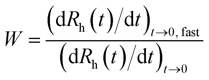 | (1) |
Results and discussion
Characterization of the bare nanosheets
It is known from the literature that TiOF2 nanosheets can be synthesized via hydrothermal routes.26,43,44 When synthesized in the form of nanosheets or nanocubes, one may use these compounds as precursor to obtain anatase nanosheets. Such a conversion can be achieved by calcination,44 by washing the fluorinated material with alkaline solutions26,36 or by performing solvothermal or hydrothermal treatments.43,45 Therefore, we have synthesized TiOF2 first for further conversion to TNS of anatase phase by alkali treatments. The synthesized precursor powder was characterized by XRD measurements. In Fig. 1, the XRD diffractograms of the precursor and of the final product are displayed with the expected ones for TiOF2 and for anatase TiO2.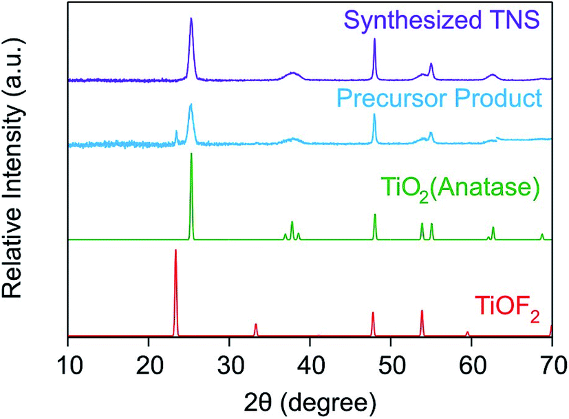 | ||
| Fig. 1 XRD diffractogram of the precursor TiOF2 and of the final TNS product obtained by alkali treatment. The theoretical diffractograms for TiOF2 and anatase (obtained from the JCPDS sheets no. 04-007-8589 and no. 00-021-1272, respectively) are also shown for comparison. | ||
The XRD pattern of the precursor product shows two characteristic peaks, namely at 2θ = 23.4° and at 2θ = 25.3° corresponding to the (100) plane of TiOF2 and to the (101) plane of TiO2, respectively. The broader peaks observed at these two 2θ values for the precursor product suggest a weak crystallization of the sample. This can originate from the action of the F− ions on the titania lattice during the hydrothermal treatment.26 Indeed, the F− ions can induce a dissolution-recrystallization of the titania lattice due to their strong affinity to titanium(IV) leading to an inhibition of the extensive bridging of the Ti–O–Ti bonds and of their crystal growth. Therefore, F− ions also act as a structure directing agent. However, the intensity of the TiOF2 peak at 2θ = 23.4° is much lower compared to the one at 2θ = 25.3° of anatase in the precursor product. This result tends to suggest that our material is essentially composed of anatase TiO2 and that some F− ions may have been incorporated in its structure or on its surface.
Xiang et al.36 reported that surface F− could be removed by alkali treatment due to a ligand exchange reaction between the F− present on the titania material and the OH− ions in solution. Moreover, the XRD pattern of the final TNS product exhibits no more peaks related to TiOF2 indicating that all the F− ions have been removed from the material during the NaOH treatment. No narrowing of any peaks took place suggesting that the crystal structure of the material was not altered by the treatment. Thus, it was speculated that the F− ions were mainly located on the surface of the material, from where they were removed through the ligand exchange reaction between the F− and OH−.
TEM images showed that the morphology and the dimensions of the nanosheets were not modified by the exposure of the material to the alkali treatment (Fig. 2a and b). The length and width distributions of the nanosheets were similar for the precursor and for the final product (Fig. S1a and S1b in the ESI†). Moreover, the thickness of the NaOH treated nanosheets was determined by AFM (Fig. 3) and was found to be 9 ± 2 nm. This value agreed quite well with the one measured by TEM (12 ± 2 nm) (Fig. S1c†). The slight difference between these values may result from the imprecise starting and ending point when using the TEM images for height measurements. Indeed, more precise values can be achieved by AFM imaging due to the sharper transition from the TNS surface to the substrate surface.
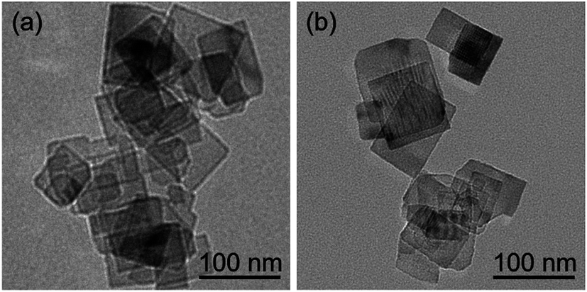 | ||
| Fig. 2 TEM images of the nanosheets (a) before and (b) after the NaOH treatment. | ||
 | ||
| Fig. 3 AFM image of a single TNS with its corresponding height profile. | ||
An important parameter to understand the charging behavior in aqueous TNS suspensions is the point of zero charge (PZC). We refer to the PZC as the value corresponding to charge neutralization of the material by the pH of the medium. Below the PZC, the material is positively charged, whereas above the PZC, it possesses negative charges. We found the charge inversion point at pH 5.2 ± 0.2 (Fig. S2†) meaning that the TNS are negatively charged at pH 9, where our experiments were carried out. The obtained PZC is similar to the ones found for other titania compounds.33,46,47
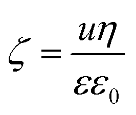
To determine the surface charge density (σ) of the TNS, the electrophoretic mobilities (u) were measured at different ionic strengths and converted to electrokinetic potentials (ζ) using the Smoluchowski equation given as:48
 | (2) |
| σ = εε0κζ | (3) |
DLS measurements in stable TNS suspensions yielded a hydrodynamic radius of 92 nm and a polydispersity index (PDI) of 0.36 (Table 1). Moreover, an average particle radius of 47 nm and a PDI of 0.30 were also determined by TEM. The PDI value is consistent with the one obtained by DLS, whereas a significant difference was found between the radii measured by DLS or TEM. Accordingly, the latter measurement yielded a much smaller value. Such a discrepancy originates from the polydispersity of the particles and from the presence of some aggregates, which are weighted more in the DLS measurements due to their higher contribution to the intensity of the scattered light.
| Material | σ a (mC m−2) | R h b (nm) | PDIb | CCCc (mM) |
|---|---|---|---|---|
| a Surface charge density obtained by electrophoresis. b Hydrodynamic radius and polydispersity index were determined in stable suspensions by DLS, where an uncertainty of about 5 nm was found for the size measurements. c Critical coagulation concentration (CCC) calculated from the stability ratio versus ionic strength plots. d The CCC was not reached within the salt concentration range studied. | ||||
| Bare TNS | −8 | 92 | 0.36 | 19 |
| TNS-PDADMAC | 13 | 109 | 0.34 | 106 |
| TNS-P(AAm-co-DADMAC) | 2 | 99 | 0.41 | —d |
Charging and aggregation in the presence of polyelectrolytes
Two different polyelectrolytes were chosen to functionalize the titania nanosheets, namely PDADMAC and P(AAm-co-DADMAC). The molecular mass of PDADMAC was similar to the one of the copolymer, therefore, the difference between them lies mostly in their charge density. Accordingly, PDADMAC is fully charged due to the quaternary amines in its structure, while P(AAm-co-DADMAC) is of lower charge density due to the presence of the neutral acrylamide groups in the block copolymer (Fig. 4). The main goal of this part of the work was to clarify the effect of the acrylamide chain on the charging and aggregation processes. | ||
| Fig. 4 Electrophoretic mobilities (a) and stability ratios (b) of TNS versus the PDADMAC or P(AAm-co-DADMAC) dose (milligrams of polyelectrolyte per gram of TNS) measured at 4.5 mM ionic strength. The chemical structures of the polyelectrolytes are shown on the top. | ||
The electrophoretic mobility and the stability ratio values of the TNS at different polyelectrolyte loading are shown in Fig. 4a and b, respectively. In general at low doses, the mobility values were negative due to the uncompensated charges of the TNS. The mobilities were slightly higher, but in the same range as the ones measured for the uncoated TNS at the corresponding ionic strength. By increasing the polyelectrolyte dose, the electrophoretic mobilities of both systems increase until charge neutralization of the TNS takes place at the isoelectric point (IEP). Here, the IEP is defined as the dose, where charge neutralization of the particles occurs by polyelectrolyte adsorption. IEPs of 2.5 mg g−1 and of 41.8 mg g−1 were found for PDADMAC and P(AAm-co-DADMAC), respectively. The difference in the IEP values lies in the fact that the charge density of P(AAm-co-DADMAC) is lower than the one of PDADMAC meaning that a higher amount of P(AAm-co-DADMAC) is needed to compensate the surface charges of the TNS compared to PDADMAC.
Above the IEP, charge reversal of the coated particles occurs due to an increase of the adsorbed amount of the polyelectrolytes on the surface. Such charge inversion is caused by specific interactions (e.g., hydrophobic forces, entropy gain or charge correlation effect) between the adsorbed polyelectrolyte chains.49–51 The electrophoretic mobility values increase until reaching the onset of the adsorption saturation plateau (ASP). The ASP corresponds to the maximum amount of polyelectrolytes that can adsorb on the surface while the remaining polyelectrolytes stay dissolved in the bulk. In the PDADMAC system, the further increase of the electrophoretic mobility after the ASP is due to the measurement of both the coated TNS and of the bare PDADMAC in solution. Similar to the IEPs, the individual systems reach the ASP at different polyelectrolyte doses, around 200 mg g−1 and 600 mg g−1 for PDADMAC and P(AAm-co-DADMAC), respectively due to their different charge density and to possible hydrophobic intermolecular interactions in the case of the copolymer. Such charge neutralization and subsequent charge reversal have already been reported for other colloidal particles in the presence of oppositely charged polyelectrolytes.30–32,34,52–55
Moreover, the stability ratios of the TNS in the same polyelectrolyte concentration range were determined (Fig. 4b). For high polyelectrolyte doses, the suspensions are stable, as indicated by high stability ratio values. By decreasing the polyelectrolyte dose, the stability ratios decrease until reaching the fast aggregation regime around 9 and 21 mg g−1 for PDADMAC and P(AAm-co-DADMAC), respectively. The value of the stability ratios is equal or lower than unity at these doses, which are close to the IEPs determined by electrophoresis. The colloidal stability of the particles is limited at low doses as indicated by the moderate stability ratio values. Below a P(AAm-co-DADMAC) dose of 2 mg g−1, a plateau is observed indicating electrostatic origin of the interparticle forces at low coverage.52 Similar aggregation behavior was found for negatively charged colloidal particles in the presence of PDADMAC56 or other positively charged polyelectrolytes.57 In these studies, a significant influence of the ionic strength on the colloidal stability was reported, however, the effect of the molecular mass of the polyelectrolytes was not significant.
Let us now discuss the possible surface forces responsible for the above mentioned aggregation behavior. When the stability ratio is equal to one, the aggregation is diffusion controlled due to the lack of repulsive interactions between the particles. This situation can be explained with the theory developed by Derjaguin, Landau, Overbeek and Verwey (DLVO) for the stability of charged colloids.40,41 Accordingly, an electrical double layer forms around the particles giving rise to repulsive forces once they overlap. However, these interactions vanish upon charge neutralization by polyelectrolyte adsorption or charge screening by simple salts. On the other hand, DLVO also predicts the continuous presence of attractive van der Waals forces. The overall interparticle force is the superposition of these repulsive and attractive interactions.
Given the definition of the stability ratio in eqn (1), lower values than unity indicate the presence of an additional (non-DLVO) force corresponding to patch-charge interactions.58 Such forces are due to the presence of positive polyelectrolyte islands adsorbed on the TNS, which interacts with the negative parts of the other partially coated TNS. Similar acceleration around the IEP has been reported in other particle-polyelectrolyte systems too.34,59,60 However, such a patch-charge attraction is more pronounced for the PDADMAC system, while it was only slightly observed for the P(AAm-co-DADMAC) samples. This fact indicates that the highly charged PDADMAC tends to form islands on the surface and the copolymer with neutral monomer groups in its structure adsorbs partially under the form of islands with the PDADMAC part on the surface and with the P(AAm) block dangling into the solution.
Another effect of the patch-charge forces is the differences in the stability ratios at low doses. The values at the same polyelectrolyte loading are much smaller for the PDADMAC system than for the P(AAm-co-DADMAC) owing to the formation of polyelectrolyte patches on the surface and to a subsequent acceleration in the aggregation for the first case. These patch-charge interactions are present only when the particles are not fully coated (i.e., when empty places are available on the surface) and disappear at high coverage leading to similar trend in the stability ratios in the present systems at high doses. Accordingly, highly stable suspensions were obtained for both the PDADMAC and the P(AAm-co-DADMAC) modified TNS at polyelectrolyte concentrations higher than the onset of the ASP. The improvement in the colloidal stability compared to the moderately stable low dose region is striking once the stability ratio values are compared.
The tendency in the stability of the TNS-PDADMAC suspensions at different doses was verified by recording TEM images with the corresponding samples (Fig. 5). At low PDADMAC dose below the IEP, the particles are moderately stable and low order of aggregates are formed (Fig. 5a). We refer to order of aggregation as the number of particles aggregating together, i.e., dimer, trimer etc. Around the IEP, the TNS form irregularly shaped clusters composed of high order of aggregates due to the unstable suspensions under these experimental conditions (Fig. 5b). It appears that during aggregation the TNS prefer to adopt a face-to-face orientation in the clusters. Similar structure has already been observed for titanate nanowires functionalized with polyelectrolytes.32,34 Moreover, for a PDADMAC dose corresponding to the onset of the ASP, the images reveal the presence of single particles along with a few dimers (Fig. 5c), which have been formed during drying in the sample preparation process for TEM imaging.
 | ||
| Fig. 5 TEM images and schemes of PDADMAC functionalized TNS at different doses (a) below the IEP at 0.1 mg g−1, (b) around the IEP at 3 mg g−1 and (c) above the IEP at 200 mg g−1 polyelectrolyte loading, which corresponds to the ASP. | ||
Stability of bare and polyelectrolyte coated TNS
Knowing the colloidal behavior of the TNS during their coating process at different polyelectrolyte doses, the next step was to investigate the properties of the nanosheets of complete polyelectrolyte coverage at different salt concentrations. The main purpose was to determine whether the coated particles exhibit higher stability compared to the bare ones or not and that which of the obtained materials could be used under physiological conditions in bioapplications.The charging of bare and coated TNS was first studied (Fig. 6a). The TNS were functionalized by adsorbing the polyelectrolytes at the onset of the ASP corresponding to doses of 200 mg g−1 and 600 mg g−1 for PDADMAC and P(AAm-co-DADMAC), respectively. From the electrophoretic mobilities, one can observe that the bare TNS possess negative charges in the entire NaCl concentration range investigated. An increase in the salt level leads to an increase in the electrophoretic mobility due to charge screening of the particle surface by the counterions.
 | ||
| Fig. 6 (a) Electrophoretic mobility and (b) stability ratio of the bare TNS, TNS-PDADMAC and TNS-P(AAm-co-DADMAC) as a function of the ionic strength adjusted by NaCl. | ||
When the TNS are coated with the polycations, they possess a positive interface at lower salt concentrations. However, the magnitude of the electrophoretic mobilities differs in this regime due to the difference in the charge density of the polyelectrolytes. The surface charge densities (Table 1 and Fig. S3†) of the coated TNS were determined from the electrophoretic results using eqn (2) and (3). For the PDADMAC coated TNS, it fell in the same range in magnitude as the one obtained for the bare TNS. However, a lower surface charge density in magnitude was found for the P(AAm-co-DADMAC) functionalized TNS compared to the uncoated TNS. Indeed, the PDADMAC block of the copolymer is adsorbed on the surface neutralizing the TNS charges, while the presence of the P(AAm) block of the copolymer of neutral charge resulted in an overall low surface charge density of the coated TNS.
In addition, the hydrodynamic radii and PDI values measured in stable suspensions were very similar to the bare one indicating that the coating procedure did not cause any aggregation of the particles. In both systems, the mobilities show a maximum, which originates from the electrokinetic effect.61 The decrease in the electrophoretic mobility value after the observed maximum is due to charge screening by the counterions present in the bulk.
For the PDADMAC coated TNS above the NaCl concentration of 450 mM, the electrophoretic mobility becomes negative and reaches a plateau around 600 mM, where the mobilities are comparable to the bare TNS at this ionic strength. The P(AAm-co-DADMAC) functionalized TNS exhibit a similar charging behavior, although the charge inversion occurred at a lower salt level, around 131 mM. The observed charge reversal process is quite surprising as it was expected that the charges would be screened by the salt ions leading to electrophoretic mobility values close to zero. The slightly negative charge in this region can originate from specific adsorption of the Cl− ions, as reported for other monovalent anions adsorbing on particle surfaces of low charge density,62 and/or from salt-induced desorption of the polyelectrolytes.63–65
The tendency in the stability ratios of the bare TNS indicates a slow aggregation range at low ionic strength and unstable suspensions at high salt concentrations (Fig. 6b). The sharp transition between these regimes occurs at a critical coagulation concentration (CCC) of 19 mM (Table 1). Similar CCCs were reported for other inorganic particles.31,34,62 Such changes in the colloidal stability are in line with the DLVO theory. The particles repel each other due to the overlap of the electrical double layers, which overcomes the attractive van der Waals forces and it gives rise to stable suspensions at low ionic strengths. On the contrary, above the CCC, the system is unstable and diffusion controlled aggregation takes place due to charge screening and subsequent vanishing of the electrical double layers.
However, the situation with the TNS-PDADMAC system is more complicated. The CCC was observed at 106 mM, therefore, PDADMAC coating of the TNS resulted in an increase in the particle stability by a factor of five, if one compares this CCC to the one for the bare TNS. Below 106 mM, the stability ratios increase with decreasing the salt level meaning that the system is stable here. Nevertheless, the slope in this slow aggregation regime is smaller than for the bare TNS indicating the presence of patch-charge attractions induced by the heterogeneous adsorption of the polyelectrolytes. Whereas above 131 mM, a slight increase in the stability ratios was observed resulting in a moderate restabilization of the suspension for higher salt concentrations.
Interpreting the results obtained at high ionic strengths for the PDADMAC functionalized TNS by electrophoresis and DLS together, one can make some assumptions on the behavior of the system. As for salt concentrations above 450 mM, the restabilization of the suspensions cannot be solely explained by the electrostatic repulsion caused by the charge reversal process, but with the involvement of conformational changes and partial desorption of the adsorbed PDADMAC chains. Indeed, an increase in the salt content may lead to a swelling of the polyelectrolyte layer as reported earlier66 and thus to a breakage of some electrostatic bonds between the PDADMAC and the negatively charged TNS. Moreover, the partial desorption and swelling of the polyelectrolyte from the TNS surface may lead to the formation of a sort of brush-like conformation of the adsorbed layer due to the appearance of more tails and loops stretching out from the TNS surface leading to steric repulsion upon their overlap.53,54,67 Such a significant effect of the salt level on the adsorption mechanism and conformation of the polyelectrolyte chains on the surface was also reported on the basis of computer simulations.68 In addition, the same theoretical method was used to study the effect of ionic strength or chain length of polyelectrolytes on the adsorption in confined spaces.69
Furthermore, it was found that the TNS-P(AAm-co-DADMAC) suspensions are stable until very high ionic strengths (above 1000 mM) and no CCC value could be determined up to 3000 mM NaCl concentration. Therefore, the coating of the TNS by this copolymer resulted in a tremendous increase (over more than a factor of 50) in the stability compared to the bare particles. This enormous stabilizing effect originates from the electrostatic and steric repulsion between the adsorbed chains. The latter one is more pronounced for polyelectrolytes of low charge density or for neutral polymers. The presence of the non-charged P(AAm) part in the P(AAm-co-DADMAC) chain certainly enhances the strength of the steric repulsion compared to the highly charged PDADMAC. Such a brushy structure of the grafted P(AAm) has also been reported for silica surfaces.70
This finding indicates that the surface functionalized nanosheets are highly stable even at the physiological ionic strength in blood (about 160 mM) making the developed material suitable for biomedical delivery processes for instance.
Conclusions
Titania nanosheets (TNS) of anatase phase were synthesized in a hydrothermal route followed by alkali treatments. The formation of the TNS was confirmed and their size and charge characteristics were determined in aqueous suspensions prior to their functionalization with two types of polyelectrolytes. The charge of the TNS was neutralized and reversed owing to the adsorption of PDADMAC or P(AAm-co-DADMAC) at appropriate doses, which vary for the different polyelectrolytes due to their dissimilar charge density. The colloidal stability was tuned by changing the polyelectrolyte loading and hence, stable or unstable dispersions could be designed. Full coverage of the nanosheet surface resulted in an improved resistance against aggregation. Accordingly, TNS-PDADMAC exhibited a 5 times increase in the stability in salt solutions compared to the bare particles. More interestingly, TNS-P(AAm-co-DADMAC) presented a tremendous increase in the colloidal stability and the suspensions were stable even at extremely high ionic strengths, where the bare and the PDADMAC coated nanosheets rapidly aggregated. Similar origin of the interparticle forces was suggested for both polyelectrolyte systems. Repulsive double layer and steric forces were responsible for the stabilization, however, the strength of the latter ones were much larger for the TNS-P(AAm-co-DADMAC). Therefore, these functionalized TNS materials appear to be suitable candidates in the field of drug delivery by acting as nanocarriers. Indeed, as the stability of the bare TNS is quite limited, the reported increase in the stability upon functionalization could facilitate, open up and extend their use in various fields.Acknowledgements
This work was supported by the Swiss Secretariat for Education, Research and Innovation (C15.0024), COST Action CM1303, University of Geneva and Swiss National Science Foundation. The authors are grateful to Celine Besnard for the XRD measurements and to Michal Borkovec for providing access to the instruments in the Laboratory of Colloid and Surface Chemistry.References
- L. Z. Wang and T. Sasaki, Chem. Rev., 2014, 114, 9455–9486 CrossRef CAS PubMed.
- Y. Bai, Z. Xing, H. Yu, Z. Li, R. Amal and L. Z. Wang, ACS Appl. Mater. Interfaces, 2013, 5, 12058–12065 CAS.
- C. Janaky, N. R. de Tacconi, W. Chanmanee and K. Rajeshwar, J. Phys. Chem. C, 2012, 116, 19145–19155 CAS.
- H. Haspel, G. Peintler and Á. Kukovecz, Chem. Phys. Lett., 2014, 607, 1–4 CrossRef CAS.
- E. F. Rodriguez, D. H. Chen, A. F. Hollenkamp, L. Cao and R. A. Caruso, Nanoscale, 2015, 7, 17947–17956 RSC.
- A. Veres, J. Menesi, C. Janaky, G. F. Samu, M. K. Scheyer, Q. S. Xu, F. Salahioglu, M. V. Garland, I. Dekany and Z. Y. Zhong, RSC Adv., 2015, 5, 2421–2428 RSC.
- B. Reti, K. Mogyorosi, A. Dombi and K. Hernadi, Appl. Catal., A, 2014, 469, 153–158 CrossRef CAS.
- R. Kun, M. Balazs and I. Dekany, Colloids Surf., A, 2005, 265, 155–162 CrossRef CAS.
- A. L. Linsebigler, G. Q. Lu and J. T. Yates, Chem. Rev., 1995, 95, 735–758 CrossRef CAS.
- E. G. Bajnoczi, N. Balazs, K. Mogyorosi, D. F. Sranko, Z. Pap, Z. Ambrus, S. E. Canton, K. Noren, E. Kuzmann, A. Vertes, Z. Homonnay, A. Oszko, I. Palinko and P. Sipos, Appl. Catal., B, 2011, 103, 232–239 CrossRef CAS.
- K. Kordás, M. Mohl, Z. Kónya and A. Kukovecz, Transl. Mater. Res., 2015, 2, 015003–015020 CrossRef.
- G. Potari, D. Madarasz, L. Nagy, B. Laszlo, A. Sapi, A. Oszko, A. Kukovecz, A. Erdohelyi, Z. Konya and J. Kiss, Langmuir, 2013, 29, 3061–3072 CrossRef CAS PubMed.
- D. Dontsova, V. Keller, N. Keller, P. Steffanut, O. Felix and G. Decher, Macromol. Rapid Commun., 2011, 32, 1145–1149 CrossRef CAS PubMed.
- X. T. Zhang, A. Fujishima, M. Jin, A. V. Emeline and T. Murakami, J. Phys. Chem. B, 2006, 110, 25142–25148 CrossRef CAS PubMed.
- V. B. Damodaran, D. Bhatnagar, V. Leszczak and K. C. Popat, RSC Adv., 2015, 5, 37149–37171 RSC.
- D. V. Bavykin and F. C. Walsh, Eur. J. Inorg. Chem., 2009, 977–997 CrossRef CAS.
- K. Kamada, A. Yamada and N. Soh, RSC Adv., 2015, 5, 85511–85516 RSC.
- A. L. Papa, L. Dumont, D. Vandroux and N. Millot, Nanotoxicology, 2013, 7, 1131–1142 CrossRef CAS PubMed.
- F. Tiarks, T. Frechen, S. Kirsch, J. Leuninger, M. Melan, A. Pfau, F. Richter, B. Schuler and C. L. Zhao, Prog. Org. Coat., 2003, 48, 140–152 CrossRef CAS.
- S. Farrokhpay, Adv. Colloid Interface Sci., 2009, 151, 24–32 CrossRef CAS PubMed.
- Y. X. Tang, Z. L. Jiang, Q. L. Tay, J. Y. Deng, Y. K. Lai, D. G. Gong, Z. L. Dong and Z. Chen, RSC Adv., 2012, 2, 9406–9414 RSC.
- R. J. Honda, V. Keene, L. Daniels and S. L. Walker, Environ. Eng. Sci., 2014, 31, 127–134 CrossRef CAS PubMed.
- J. Grzechulska, M. Hamerski and A. W. Morawski, Water Res., 2000, 34, 1638–1644 CrossRef CAS.
- Y. W. L. Lim, Y. X. Tang, Y. H. Cheng and Z. Chen, Nanoscale, 2010, 2, 2751–2757 RSC.
- H. Brahmi, G. Katwal, M. Khodadadi, S. Chen, M. Paulose, O. K. Varghese and A. Mavrokefalos, Nanoscale, 2015, 7, 19004–19011 RSC.
- Z. Y. Wang, K. L. Lv, G. H. Wang, K. J. Deng and D. G. Tang, Appl. Catal., B, 2010, 100, 378–385 CrossRef CAS.
- Y. L. Yu, P. Zhang, L. M. Guo, Z. D. Chen, Q. Wu, Y. H. Ding, W. J. Zheng and Y. Cao, J. Phys. Chem. C, 2014, 118, 12727–12733 CAS.
- X. L. Ding, X. Q. Yang, L. Zhou, H. B. Lu, S. B. Li, Y. Gao, C. H. Lai and Y. Jiang, Int. J. Nanomed., 2013, 8, 569–579 Search PubMed.
- A. L. Papa, J. Boudon, V. Bellat, A. Loiseau, H. Bisht, F. Sallem, R. Chassagnon, V. Berard and N. Millot, Dalton Trans., 2015, 44, 739–746 RSC.
- T. Szabo, V. Toth, E. Horvath and I. Szilagyi, Chimia, 2014, 68, 454 CrossRef CAS.
- T. Szabo, V. Toth, E. Horvath, L. Forro and I. Szilagyi, Langmuir, 2015, 31, 42–49 CrossRef CAS PubMed.
- M. Pavlovic, M. Adok-Sipiczki, E. Horvath, T. Szabo, L. Forro and I. Szilagyi, J. Phys. Chem. C, 2015, 119, 24919–24926 CAS.
- E. Horvath, I. Szilagyi, L. Forro and A. Magrez, J. Colloid Interface Sci., 2014, 416, 190–197 CrossRef CAS PubMed.
- E. Horvath, L. Grebikova, P. Maroni, T. Szabo, A. Magrez, L. Forro and I. Szilagyi, ChemPlusChem, 2014, 79, 592–600 CrossRef CAS.
- X. G. Han, Q. Kuang, M. S. Jin, Z. X. Xie and L. S. Zheng, J. Am. Chem. Soc., 2009, 131, 3152–3153 CrossRef CAS PubMed.
- Q. J. Xiang, K. L. Lv and J. G. Yu, Appl. Catal., B, 2010, 96, 557–564 CrossRef CAS.
- H. Holthoff, S. U. Egelhaaf, M. Borkovec, P. Schurtenberger and H. Sticher, Langmuir, 1996, 12, 5541–5549 CrossRef CAS.
- K. L. Chen, S. E. Mylon and M. Elimelech, Langmuir, 2007, 23, 5920–5928 CrossRef CAS PubMed.
- L. Ehrl, Z. Jia, H. Wu, M. Lattuada, M. Soos and M. Morbidelli, Langmuir, 2009, 25, 2696–2702 CrossRef CAS PubMed.
- G. Trefalt, I. Szilagyi and M. Borkovec, J. Colloid Interface Sci., 2013, 406, 111–120 CrossRef CAS PubMed.
- B. Derjaguin, Trans. Faraday Soc., 1940, 35, 0203–0214 RSC.
- C. Henry, K. K. Norrfors, M. Olejnik, M. Bouby, J. Luetzenkirchen, S. Wold and J. P. Minier, Adsorption, 2016, 22, 503–515 CrossRef CAS.
- Z. A. Huang, Z. Y. Wang, K. L. Lv, Y. Zheng and K. J. Deng, ACS Appl. Mater. Interfaces, 2013, 5, 8663–8669 CAS.
- K. L. Lv, J. G. Yu, L. Z. Cui, S. L. Chen and M. Li, J. Alloys Compd., 2011, 509, 4557–4562 CrossRef CAS.
- Z. Y. Wang, B. B. Huang, Y. Dai, X. L. Zhu, Y. Y. Liu, X. Y. Zhang and X. Y. Qin, CrystEngComm, 2013, 15, 3436–3441 RSC.
- A. Niecikowska, M. Krasowska, J. Ralston and K. Malysa, J. Phys. Chem. C, 2012, 116, 3071–3078 CAS.
- M. Lorenzetti, E. Gongadze, M. Kulkarni, I. Junkar and A. Iglic, Nanoscale Res. Lett., 2016, 11, 378–390 CrossRef PubMed.
- A. V. Delgado, F. Gonzalez-Caballero, R. J. Hunter, L. K. Koopal and J. Lyklema, J. Colloid Interface Sci., 2007, 309, 194–224 CrossRef CAS PubMed.
- J. Forsman, Langmuir, 2012, 28, 5138–5150 CrossRef CAS PubMed.
- J. C. Fu and J. B. Schlenoff, J. Am. Chem. Soc., 2016, 138, 980–990 CrossRef CAS PubMed.
- M. Quesada-Perez, E. Gonzalez-Tovar, A. Martin-Molina, M. Lozada-Cassou and R. Hidalgo-Alvarez, ChemPhysChem, 2003, 4, 235–248 CrossRef CAS PubMed.
- J. Hierrezuelo, A. Sadeghpour, I. Szilagyi, A. Vaccaro and M. Borkovec, Langmuir, 2010, 26, 15109–15111 CrossRef CAS PubMed.
- E. Illes and E. Tombacz, J. Colloid Interface Sci., 2006, 295, 115–123 CrossRef CAS PubMed.
- F. Brunel, I. Pochard, S. Gauffine, M. Turesson and C. Labbez, J. Phys. Chem. B, 2016, 120, 5777–5785 CrossRef CAS PubMed.
- E. D. E. Hyde, R. Moreno-Atanasio, P. A. Millner and F. Neville, J. Phys. Chem. B, 2015, 119, 1726–1735 CrossRef CAS PubMed.
- A. Fuchs and E. Killmann, Colloid Polym. Sci., 1998, 279, 53–60 Search PubMed.
- I. Szilagyi, D. Rosicka, J. Hierrezuelo and M. Borkovec, J. Colloid Interface Sci., 2011, 360, 580–585 CrossRef CAS PubMed.
- Y. K. Leong, Colloid Polym. Sci., 1999, 277, 299–305 CAS.
- S. Schwarz, S. Bratskaya, W. Jaeger and B. R. Paulke, J. Appl. Polym. Sci., 2006, 101, 3422–3429 CrossRef CAS.
- J. Hierrezuelo, A. Vaccaro and M. Borkovec, J. Colloid Interface Sci., 2010, 347, 202–208 CrossRef CAS PubMed.
- M. Borkovec, S. H. Behrens and M. Semmler, Langmuir, 2000, 16, 5209–5212 CrossRef CAS.
- M. Pavlovic, R. Huber, M. Adok-Sipiczki, C. Nardin and I. Szilagyi, Soft Matter, 2016, 12, 4024–4033 RSC.
- S. T. Dubas and J. B. Schlenoff, Macromolecules, 2001, 34, 3736–3740 CrossRef CAS.
- H. Mjahed, J. C. Voegel, B. Senger, A. Chassepot, A. Rameau, V. Ball, P. Schaaf and F. Boulmedais, Soft Matter, 2009, 5, 2269–2276 RSC.
- L. L. Han, Z. W. Mao, H. Wuliyasu, J. D. Wu, X. Gong, Y. G. Yang and C. Y. Gao, Langmuir, 2012, 28, 193–199 CrossRef CAS PubMed.
- E. Seyrek, J. Hierrezuelo, A. Sadeghpour, I. Szilagyi and M. Borkovec, Phys. Chem. Chem. Phys., 2011, 13, 12716–12719 RSC.
- R. Meszaros, I. Varga and T. Gilanyi, Langmuir, 2004, 20, 5026–5029 CrossRef CAS PubMed.
- A. G. Cherstvy and R. G. Winkler, J. Phys. Chem. B, 2012, 116, 9838–9845 CrossRef CAS PubMed.
- S. J. de Carvalho, R. Metzler and A. G. Cherstvy, Soft Matter, 2015, 11, 4430–4443 RSC.
- A. Li, S. N. Ramakrishna, E. S. Kooij, R. M. Espinosa-Marzal and N. D. Spencer, Soft Matter, 2012, 8, 9092–9100 RSC.
Footnote |
| † Electronic supplementary information (ESI) available. See DOI: 10.1039/c6ra23707j |
| This journal is © The Royal Society of Chemistry 2016 |