DOI:
10.1039/C6RA23061J
(Paper)
RSC Adv., 2016,
6, 99867-99877
The effect of phenol functionality on the characteristic features and performance of fully aromatic polyester thin film composite nanofiltration membranes†
Received
15th September 2016
, Accepted 10th October 2016
First published on 11th October 2016
1 Introduction
Thin film composite (TFC) membranes comprising a top barrier layer generally behave as either nanofiltration (NF) or reverse osmosis (RO) membranes. The top barrier layer of thickness 100–200 nm is obtained by interfacial polymerization (IP) between reactive monomers taken in aqueous and non-aqueous phases. The barrier layer is mostly cross-linked polyamide (PA) and the membrane is termed a PA TFC membrane. There are two types of PA TFC membranes: (i) fully aromatic TFC membranes prepared by IP between m-phenylenediamine (MPD) and trimesoyl chloride (TMC)1–4 and (ii) partially aromatic TFC membranes prepared by IP between piperazine and TMC or related acid chlorides.5–9 The latter function as NF membrane, with selective permeation of certain constituents and rejection of others. Such membranes have a molecular weight cut off typically in the range of 200–1000 g mol−1. NF membrane-based separation is important in various industrial applications and also in treatment techniques for potable water production. The advantages of NF include high permeate flux even at low operating pressure, and ability to carry out separation processes even with solutions containing high concentrations of dissolved salts. A useful application of NF membrane is the selective removal of divalent ions from seawater, which reduces the problem of RO membrane fouling during desalination besides reducing the overall total dissolved solids (TDS) in the feed water and, consequently, its osmotic pressure. Another useful application is that the treated water can be made fit for use in applications such as preparation of brine for the Solvay process. In a typical negatively charged PA NF membrane, sodium chloride shows low rejection (25–50%) whereas sulphate salts show rejection as high as 99%, i.e., high discrimination between the mono- and divalent anions on account of sieving and electrostatic effects. Sieving effect is related to solute size in relation to membrane pore size, while charge effect is explained by the Donnan exclusion phenomenon arising from electrostatic interactions between ions and membrane surface charges.5–9 TFC PA membranes can be bestowed with negative or positive charge.9–13 When excess acid chloride groups remain unreacted, as is the case for poly(piperazineamide) membrane, it is left with a negative charge. These undergo hydrolysis and remain in ionized form when pH ≥ pKa. The rejection efficiencies of NaCl, MgCl2 and Na2SO4 follow the trend: Na2SO4 > NaCl > MgCl2,9,10 which is attributed to the enhanced charge–charge repulsion between SO42− and membrane surface whereas the Mg2+ ion experiences electrostatic attraction with the negatively charged membrane surface, facilitating its transport through the barrier layer. Ionic size also matters additionally.
TFC polyester (PE) membranes have been less well studied. Kwak et al. attempted the preparation of PE TFC RO membranes through the IP between TMC and various bisphenol monomers such as 4,4′-dihydroxybiphenyl, 2,2-bis(4-hydroxyphenyl) propane, dihydroxydiphenyl ether and bis(4-hydroxyphenyl)sulfone.14 It was found that the polarity and size of the connector group in bisphenol had pronounced effect on surface morphology and RO performance. The membranes exhibited 40–60% NaCl rejection efficiency for aqueous feed containing 2000 ppm NaCl. The fluxes of the different PE membranes were reported to be low (0.7–2.5 L atm−1 m−2 h−1). Seman et al. have prepared PE NF membranes from TMC and bisphenol A.15 The work was focused on the study of antifouling properties of the prepared membranes in presence of humic acid at neutral pH. These researchers did not evaluate the salt rejection characteristics of the prepared membranes. Tang et al. reported the preparation of PE TFC NF membrane with good stability and with an isoelectric point in the range of 4–5 pH via the IP between triethanolamine and TMC on polysulfone (PSf) membrane support. The rejection of different salts decreased as per the order: Na2SO4, 82.2%; MgSO4, 76.5%; NaCl, 42.2%; MgCl2, 23%, while the flux varied from 8.4 to 11.5 L m−2 h−1 when the applied pressure was 0.6 MPa.10 Apart from the fact that the rejection of Na2SO4 was moderate, the flux was too low for practical applications. There are also reports of hyper-branched PE membrane,16,17 tannic acid-based TFC membrane,18 and composite carbon nanotube/PE TFC membrane.19
The main objective of the present work was the preparation of new types of PE TFC NF membranes from low cost resorcinol (Res) and phloroglucinol (Phg) as phenolic monomers, and the study of the effect of phenolic functionality on the surface morphology, surface roughness and performance of the membranes. The optimized Res to Phg ratio and absolute concentrations were evaluated to achieve best NF performance. It was revealed that the surface roughness, extent of ridge-valley type of structure formation, rejection efficiency and permeate flux were enhanced with the increasing Phg to Res ratio in the aqueous bath. The pH window over which these PE membranes are stable was also ascertained. From the perspective of cost and membrane processing, phenols are more affordable and exhibit higher oxidative stability than the corresponding amines. This was yet another motivation behind the study. An important observation made with this PE membrane was the lower rejection of divalent cation compared to that found with PA NF membranes. This provides an opportunity to selectively separate divalent cations and divalent anions. To the best of our knowledge preparation of NF membranes employing these phenols as monomers is not reported in the literature.
2 Experimental
2.1 Materials
PSf (Udel P-3500) was procured from Solvay Polymers and dried at 80 °C for 2 h prior to the preparation of the casting solution in dimethylformamide (DMF) solvent. TMC from Aldrich (98%) was used as received. Analytical grade DMF, hexane, triethylamine, Res, Phg, sucrose, polyethylene glycol (PEG) samples, sodium hypochlorite (NaOCl), NaCl, NaBr, KCl, NaF, Na2SO4, MgCl2, CaCl2, MgSO4, Na2HAsO4 and NaAsO2 were sourced from Spectrochem, India and used as received. Non-woven PE fabric (Nordlys-TS100) was also used as received.
2.2 Preparation of ultrafiltration membrane by phase inversion
The PSf support membrane was prepared on non-woven fabric as reported previously.20 Briefly, PSf (15%, w/w) was dissolved in DMF at 70 °C to prepare the casting solution. The solution was allowed to settle for 12 h at room temperature to ensure complete release of air bubbles. Then, the PSf solution was cast on the non-woven fabric by semi-automatic blade casting machine at 4 m min−1 rate followed by passing through a gelation bath containing 0.1% (w/v) sodium lauryl sulphate in H2O/DMF (H2O![[thin space (1/6-em)]](https://www.rsc.org/images/entities/char_2009.gif) :DMF = 96:4 v/v). The gap of the blade from the platform surface was adjusted to obtain a PSf film thickness of 30–40 μm. The resultant membrane was then washed with water and stored in RO-water. The PSf membrane showed ∼100 kDa molecular weight cut-off (MWCO) and gave ∼650 L m−2 h−1 pure water flux at 0.35 MPa.
:DMF = 96:4 v/v). The gap of the blade from the platform surface was adjusted to obtain a PSf film thickness of 30–40 μm. The resultant membrane was then washed with water and stored in RO-water. The PSf membrane showed ∼100 kDa molecular weight cut-off (MWCO) and gave ∼650 L m−2 h−1 pure water flux at 0.35 MPa.
2.3 Preparation of PE TFC membranes
PE TFC membrane on PSf ultrafiltration membrane support was prepared through IP of TMC with Res [(pKa)1 = 9.32; (pKa)2 = 9.81]21 or trifunctional Phg [(pKa)1 = 8.0; (pKa)2 = 9.2; (pKa)3 = 14.0]22 or mixture of Res and Phg. The concentration of TMC in hexane bath was varied from 0.1–0.5% (w/v) and Res concentration in aqueous bath was varied from 1–3%. A typical example of preparation of PE TFC membrane is as follows: 3% (w/v) solution of Res was prepared in RO-filtered water and the pH (determined by calibrated pH meter; Eutech Instruments) was adjusted to 9 through dropwise addition of triethylamine. Next, the water-wetted PSf support membrane was attached on a glass slide with the help of tape and immersed in the aqueous solution of Res to soak for at least 2 min and then removed from the solution. The surface of the membrane was gently rolled with a soft rubber roller to eliminate small bubbles which may have formed during the process of soaking. The membrane was then dipped into a 0.3% (w/v) solution of TMC in hexane for 1 min. It was thereafter heat cured at 70 °C for 3 min, washed several times with water, and finally stored in 10% (w/v) glycerol in water. Different PE TFC membranes were prepared using the same procedure as discussed above. Table 1 summarizes the compositions employed for the preparation of various membranes along with membrane nomenclature.
Table 1 Bath compositions employed for various TFC PE membrane preparations along with nomenclature of the membranes
| Entry |
Res (%, w/v) |
Phg (%, w/v) |
TMC (%, w/v) |
TFC PE membrane |
| 1 |
3 |
0 |
0.3 |
TFC1 |
| 2 |
2.75 |
0.25 |
0.3 |
TFC2 |
| 3 |
2.5 |
0.5 |
0.3 |
TFC3 |
| 4 |
2 |
1 |
0.3 |
TFC4 |
| 5 |
1 |
2 |
0.3 |
TFC5 |
| 6 |
0 |
3 |
0.3 |
TFC6 |
2.4 Characterization
2.4.1 Attenuated total reflection infrared (ATR-IR) analysis, contact angle, zeta potential, scanning electron microscopy (SEM) and atomic force microscopy (AFM). ATR-IR spectra of the TFC membrane coupons (3 cm × 6 cm) were recorded on Agilent Cary 600 series FTIR at room temperature. Spectra were recorded at 5 different positions.20 The density of ester groups per unit area (DEG), which depends on completeness of esterification of functional groups, film thickness and compactness, is defined by eqn (1),where I1743 is the intensity of carbonyl stretching due to the ester group at 1743 cm−1 and I1585 is the intensity due to the C![[double bond, length as m-dash]](https://www.rsc.org/images/entities/char_e001.gif) C aromatic stretching of PSf at 1585 cm−1. It was reported that the intensity of 1585 cm−1 band changes insignificantly upon TFC formation and other modifications, unless the thickness of the top layer exceeds the penetration depth of evanescent IR wave (∼1 μm).20 The reported DEG values are the average of the reading at five spots per sample. Similar ratio was worked out for I1207/I1585 where I1207 is the intensity of C–O–C stretching of ester group.
C aromatic stretching of PSf at 1585 cm−1. It was reported that the intensity of 1585 cm−1 band changes insignificantly upon TFC formation and other modifications, unless the thickness of the top layer exceeds the penetration depth of evanescent IR wave (∼1 μm).20 The reported DEG values are the average of the reading at five spots per sample. Similar ratio was worked out for I1207/I1585 where I1207 is the intensity of C–O–C stretching of ester group.Water contact angle and zeta potential of the membranes were measured as described in an earlier report.20 SEM and AFM images were recorded as per earlier procedure.20 The cross-sectional SEM images were recorded on freshly cut membranes. Firstly, the membranes were frozen with liquid nitrogen and then cross-sectioned with a sharp blade. The freshly cut membranes were dried initially in air and thereafter in CaCl2 desiccator. These were then placed on SEM sample holder and were coated with gold in a sputter coater (Sputter Coater SC7620). Coating was undertaken for 3 min under vacuum. The SEM (JEOL JSM 7100F) analysis was then performed at different magnifications. AFM images were recorded in an Ntegra Aura (Nt-Mdt, Moscow) instrument at room temperature in air, employing “Nova” software for image analysis. Prior to recording of images, membrane surfaces were cleaned thoroughly with distilled water to make these dust free. These were then dried in a vacuum oven and stored in CaCl2 desiccator.
2.4.2 Estimation of permeability coefficient, pore radius, and film thickness to porosity ratio from permeability studies with neutral solutes. The permeability coefficient (Lp), effective pore radius (rp), and pore structure factor (lp/εp) (where, lp = thickness and εp = porosity) of the PE membranes were calculated from the Hagen–Poiseuille pore flow model as reported earlier.23–25
2.4.3 MWCO estimation with PEG standards. Rejection studies with PEG polymers (500 ppm in distilled water, pH ∼ 7) of different molecular weights (200 g mol−1, 400 g mol−1, 600 g mol−1, 1000 g mol−1 and 2000 g mol−1) were carried out in recirculation mode at applied pressure of 0.5 MPa. Permeate was collected after 1 h of pressurization. Equal volume of feed and permeate solutions were then injected into GPC system through the automatic injection loop. The GPC was carried out at room temperature on different ultra-hydrogel columns (ultrahydrogel 120 and ultrahydrogel 250) connected in series. Water was used as eluent (1 mL min−1). PEG samples of different molecular weights were used as calibration standards. Rejection of PEG was estimated from the areas under the GPC traces of feed and permeate solution. The MWCO was calculated at 90% rejection of the solute.
2.5 Ionic salt separation performance
The performances of the membranes were evaluated in a reverse osmosis test kit using 1500 ppm Na2SO4, NaCl, NaBr, KCl, CaCl2 and MgCl2 as feed solutions. Adjustment of pH was carried out through addition of either HCl or NaOH. The test kit consisted of four SS316 cells connected in series in a cross-flow setup. The cell could accommodate circular membrane coupons of 3.5 cm diameter (15 cm2 area). The kit was additionally equipped with high pressure pump, pressure-gauge, pressure-control valve and conductivity meter. After fixing the membrane circles in the test cells, the permeation data were recorded at 0.5 MPa after initial pressurization at 0.7 MPa for 1 h to obtain steady flux. The cross flow rate was ca. 100 L h−1. The permeate flux, J (L m−2 h−1), was calculated using eqn (2),wherein V is the volume of water permeated (L), A is the membrane area (m2) and t is the permeate time (h). The salt concentrations in the feed and permeate were determined by measuring the conductivity of the solutions using digital conductivity meter. Average value of 4–6 coupons was taken and standard deviation estimated. Rejection was computed from eqn (3).| | |
Rejection (%) = (1 − Cp/Cf) × 100
| (3) |
wherein Cp and Cf stand for the salt concentrations in the permeate and feed, respectively.
Fluoride concentrations in feed and permeate were determined by Expandable Ion Analyzer EA940 from Orion Research. Arsenic concentration was determined using a semi-quantitative arsenic detection kit. Concentration was estimated through colour matching.
2.6 pH and chlorine stability
Performances of four coupons of TFC5 membrane were evaluated with 1500 ppm Na2SO4 feed as described in Section 2.5. The membrane coupons were then immersed in water of different pH for different periods. Performance was re-evaluated after repeat exposure to water of different pH. Similarly, performance of TFC5 was assessed after exposure to different concentrations (0–50 ppm) of NaOCl solution for 60 h each.
3 Results and discussion
3.1 Preparation of aromatic PE NF membranes
Initial efforts were oriented toward the optimization of the concentration and composition of aqueous reaction bath and hexane bath for IP. Standardization experiments revealed that PE TFC membranes prepared with total 3% (w/v) Res and Phg mixture (Phg:Res = 2:1, w/w) in aqueous medium and TMC concentration of 0.3% (w/v) in hexane gave best permeate water flux and rejection of Na2SO4 (vide infra and Fig. S1, ESI†). Hence, different PE TFC membranes (TFC1 to TFC6) were prepared by IP between TMC (0.3%, w/v) and Res (3%, w/v) or Phg (3%, w/v) or mixture of Res and Phg (total 3%, w/v) (Table 1). TFC PE membrane (TFC7) was also prepared by IP between bi-functional resorcinol and bi-functional isophthaloyl chloride on PSf support to compare the characteristic features and properties of this membrane with other membranes. Scheme 1 shows the probable structures of PE which may form in the cases of TFC1 (Table 1, entry 1), TFC5 (Table 1, entry 5), TFC6 (Table 1, entry 6) and TFC7. The cross-linking density of formed PE depends on functionality of monomers. For example, since both the phenol (Res) and acid chloride (isophthaloyl chloride) are bi-functional, only a linear PE formation is feasible in TFC7 (Scheme 1). This PE was soluble in DMF due to its uncross-linked nature. Since the functionality of Phg monomer is higher than Res, the cross-linking density in PE should be relatively higher in TFC5 and TFC6 compared to that of TFC1. The Scheme 1 also shows that there is probability of formation of the branched and linear PE in case of TFC1, whereas TFC5 and TFC6 should mainly exist in the form of cross-linked PE. These PE structures of different TFC membranes are most probable as was judged by ATR-IR and cross-sectional SEM, and also by filtration experiments (vide infra).
 |
| | Scheme 1 Proposed structures of TFC1, TFC5, TFC6 and TFC7. | |
3.2 Characteristic features
3.2.1 ATR-IR and cross-sectional SEM study. Fig. 1A shows the ATR-IR spectra of the membranes of Table 1 and TFC7. The IR bands at 1743 cm−1 and 1207 cm−1 were seen for all the membranes and are ascribed to the CO and C–O–C stretching vibrations of ester group, respectively. All spectra also showed the presence of PSf band at 1585 cm−1 due to CC aromatic stretching.26 For a fixed penetration depth of the IR beam, the ratio of signal intensity due to the ester functionality to the signal intensity of PSf band should increase with (i) increasing PE film thickness, (ii) completeness of reaction, and (iii) compactness of film structure. The intensity of 1743 cm−1 band (I1743) decreased dramatically with substitution of Res with Phg. As a result, I1743/I1585 decreased steeply initially and the effect tapered off subsequently (Fig. 1B). The I1207/I1585 also followed a similar trend. The drop in I1743/I1585 and I1207/I1585 with increasing proportion of added Phg may be explained on the basis of Scheme 1. When the acid chloride is tri-functional and the phenolic monomer is bi-functional, the cross-linking density would be lower than when both are tri-functional. Lower cross-linking density would allow phenolic monomer to diffuse across the growing polymer film towards the interface for continuous reaction with TMC. On the other hand, when the acid chloride is tri-functional and phenolic monomer is either tri-functional or a mixture of bi- and tri-functional phenols, more extended network structure would be expected which would thwart the diffusion of phenolic monomer towards TMC and inhibit the formation of a thick film. This explanation is supported through an additional experiment with a fully linear TFC membrane (TFC7) prepared using bi-functional isophthaloyl chloride and Res. The IR spectrum of the resultant membrane (TFC7) showed much enhanced I1743 to I1585 ratio compared to the other membranes, indicative of a thicker film. Higher thickness of TFC7 was also evident from extremely low flux (4–5 fold lower) of this membrane compared to the other membranes. As such, film thickness ∝ f−1/3, f being the total functionality of the monomers.27 Variation of thickness with phenol functionality was also confirmed by cross-sectional SEM analysis (Fig. 2). The cross-sectional SEM images of the membranes showed that the PE thickness was ∼270 nm in TFC1 (image A) whereas the corresponding values were ∼160 nm and ∼100 nm in TFC5 and TFC6, respectively (images B and C). The latter values were considerably lower than that of TFC1. Thus thicknesses obtained from the cross-sectional SEM images were consistent with the I1743/I1585 and I1207/I1585 values of TFC membranes.
 |
| | Fig. 1 (A) ATR-IR spectra (bottom to top) of TFC7, TFC1, TFC2, TFC3, TFC4, TFC5, and TFC6. (B) Effect of Phg on I1743/I1585 and I1207/I1585 (filled symbols). I1743/I1585 and I1207/I1585 for TFC7 are also shown (open symbols). | |
 |
| | Fig. 2 Cross-sectional SEM images of TFC1 (A and A′), TFC5 (B and B′), and TFC6 (C and C′). (A–C) and (A′–C′) were recorded at 50 K and 80 K magnification, respectively. | |
3.2.2 Morphology of the membranes by SEM and AFM analyses. The surface morphology of different membranes was probed by SEM analysis (Fig. 3). Compared to the image of PSf membrane (image A), TFC7 (image B) revealed a smooth and featureless surface whereas TFC1 was less uniform (image C) with some patches resembling TFC7 and other portions resembling a fractal surface. This indicates that some portions of the TFC1 membrane surface are similar to that of TFC7. This is probably due to the presence of uncross-linked PE. The SEM images (images D–G) of TFC3, TFC4, TFC5 and TFC6, which were prepared using increasingly higher proportions of Phg in aqueous bath, showed increasingly greater regularity of the fractal nature of the surface. The SEM images of TFC5 and TFC6 were more alike than others. Thus it may be stated that the roughness of the membrane surface increased with increasing amount of Phg used for IP due to the increasing cross-linking of formed PE.
 |
| | Fig. 3 SEM images showing surface morphology: (A) PSf support membrane, (B) TFC7, (C) TFC1, (D) TFC3, (E) TFC4, (F) TFC5 and (G) TFC6. Arrows indicate smooth featureless surface. | |
Membrane morphology was further probed by AFM (Fig. 4). TFC1 showed a smooth surface (image A) whereas the surface roughness increased from TFC3 to TFC5 to TFC6 (images B–D).
 |
| | Fig. 4 AFM topological (left) and height (right) images showing surface morphology of (A) TFC1, (B) TFC3, (C) TFC5 and (D) TFC6. | |
Except TFC1 (image A) and TFC7 (not included in figure), the height images of the other membranes showed the ridge-valley morphology. The root mean square roughness values of the membranes were calculated to be 100 nm, 140 nm, 179 nm and 187 nm for TFC1, TFC3, TFC5 and TFC6, respectively. The enhanced roughness of the membranes may be ascribed to the increased proportion of cross-linked structure with increasing proportion of Phg (Scheme 1). The surface properties of model TFC7 containing uncross-linked PE and TFC1 membrane were similar, indicating low degree of cross-linking in the latter compared to the other membranes.
3.2.3 Water contact angle and zeta potential of the membranes. The surface hydrophilic character of the PE TFC membranes were determined by water contact angle measurements. The values varied from 58° to 64° for TFC1 to TFC6, i.e., no significant difference was seen when Res was partially or fully substituted with Phg. Fig. 5 shows the variation of surface zeta potential values of TFC1, TFC5 and TFC6 with the variation of the pH. The data were recorded in the pH range of 6–9 considering that most of the salt solutions of practical interest would fall in this range. As can be seen from the Fig. 5, zeta potential became more negative in going from pH 6 to pH 7, due to higher degree of dissociation of residual –CO2H in the membrane.
 |
| | Fig. 5 Variation of zeta potential with the variation of pH for TFC1, TFC5 and TFC6 (temperature ca. 26 °C). | |
3.2.4 rp and lp/εp of the membranes. Several models have been proposed to understand separation processes of NF membranes. Simplest of these are the pore and charge models based on sieving effect and electrostatic effect, respectively.25,26,28 Models combining both the effects such as the electrostatic steric-hindrance model and the Donnan steric pore model have been proposed by Bowen and coworkers29 and Nakao et al.30 Since the profiles of zeta potential versus pH, as also the absolute values of zeta potential, were comparable for TFC1, TFC5 and TFC6, the observed differences in the rejection characteristics of different electrolytes at TFC1, TFC5 and TFC6 were more likely on account of variations in rp (vide infra). Fig. 6 shows the rejection of different PEG standards observed for experiments on TFC1, TFC5 and TFC6. Based on the plots, their MWCO values were determined and the data are presented in Table 2. Unusual PEG rejection is observed in the case of TFC1 as the rejection remained almost constant (ca. 88–89%) for PEG of molecular weight 600 g mol−1 (solute radius = 0.67 nm) and 1000 g mol−1 (solute radius = 0.9 nm). This indicates that the pore size distribution of TFC1 is much wider than that of the other membranes owing to low and non-uniform cross-linking. This strongly suggests the likely presence of uncross-linked (linear or branched) PE chains along with cross-linked PE in the active layer of TFC1. Table 2 also provides data of rp derived from the steric model.23–25 PE films with Res gave higher rp whereas the value was the lowest for pure Phg. These results are consistent with the differences in cross-linking density of the PE films due to the differences in the functionalities of the two phenols. Variations were also seen in the values of Lp and lp/εp of the three membranes. TFC1 exhibited lower Lp and higher lp/εp compared to TFC5 and TFC6 due to the formation of a relatively thicker PE film as evident from the ATR-IR (Fig. 1) and cross-sectional SEM images (Fig. 2) discussed above. Interestingly, the rp and lp/εp of TFC5 and TFC6 were close to the values reported for the commercial CA30 NF membrane.25 Desirable permeation properties were obtained with TFC5 and TFC6 membranes likely on this count. The permeation characteristics of the membranes were further investigated by comparative performance evaluation studies.
 |
| | Fig. 6 Variation of PEG rejection as a function of molecular weight in experiments conducted with TFC1, TFC5 and TFC6. The pH of the aqueous feed solutions was ∼7 and the temperature 28 °C. | |
Table 2 Characteristics data of PE TFC membranes
| PE TFC |
Zeta potential (mV) at pH 7 |
Lp (μm MPa−1 s−1) |
lp/εp (μm) |
PEG MWCO (g mol−1) |
Sucrose rejection (%)/rp (nm) |
| TFC1 |
−29 |
11.8 |
8.42 |
∼1000 |
66/0.89 |
| TFC5 |
−32 |
20.8 |
3.74 |
450 |
75/0.79 |
| TFC6 |
−31.5 |
19.7 |
3.65 |
420 |
78/0.76 |
3.3 Performance and applications of PE TFC membranes
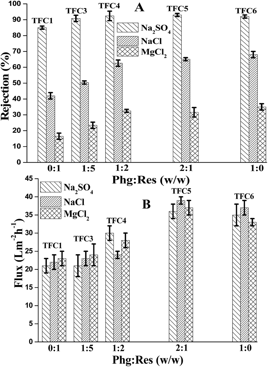
Fig. 7A and B provide comparative data of rejection and permeate flux of TFC1, TFC3, TFC4, TFC5 and TFC6 PE membranes during NF of pure solutions of 1500 ppm NaCl, MgCl2 and Na2SO4. The absolute rejection of the above salts increased with increasing proportion of Phg up to the ratio of 2:1 (w/w) (TFC5). Upon elimination of Res altogether (TFC6), the rejections improved further in the cases of NaCl and MgCl2, whereas it was similar in the case of Na2SO4. The relative rejection followed the trend MgCl2 < NaCl < Na2SO4 for all the membranes, which was consistent with results reported in the literature for negatively charged NF membrane.9,10 Since the zeta potential values of our PE membranes were similar, the improvement in rejection with increasing proportion of Phg in the aqueous bath was likely due to the lowering of rp (Table 2). In other words, the higher degree of cross-linking in the membranes prepared with increasing proportion of Phg lowered the rp and, as a consequence, the rejection increased. Among the ions studied, SO42− possesses the largest ionic radius if only the first hydration shell is considered. SO42− would also be repelled the most by the negatively charged membrane (Table S1, ESI†).31,32 Both factors would hinder its transport. In contrast, ionic radius of Mg2+ is the smallest among the ions considered in Table S1 considering the first hydration shell data in Table S1 (ESI†). Moreover, Mg2+ will exert maximum electrostatic attraction towards the membrane. Both factors would therefore facilitate its permeation the most. Thus the observed trend of salt rejection can be understood. Further analysis of the rejection data in Fig. 7A revealed that the TFC6 to TFC1 salt rejection ratios were 1.62, 2.12 and 1.08 for NaCl, MgCl2 and Na2SO4, respectively. Consequently, the discrimination among the three salts reduced in the case of TFC6. Since all the membranes gave similar values of zeta potential, an explanation was sought based on size effects. It is reported that the sizes of the cations (Table S1, ESI†) expand considerably when the second hydration shell is considered.31,32 Thus the size of Na+ increases from 0.236 nm to 0.450–0.480 nm while that of Mg2+ increases from 0.209 nm to 0.410–0.428 nm. Computations are not provided for the second hydration shell of anions but the effect is likely to be much less pronounced. Size-based arguments would suggest that, due to the large size of Na+ bearing a second hydration shell, the NaCl solute would exhibit increasingly higher rejection on TFC5 and TFC6 (membranes having smaller rp) compared to MgCl2 and Na2SO4. However, as mentioned above, the maximum enhancement of rejection was seen in the case of MgCl2. It is proposed that under the conditions of the separation process, the second hydration shell of Na+ may be more vulnerable to disruption compared to the second hydration shell of Mg2+; the latter is likely to be more tenaciously held due to the higher hydration energy. This may retard relatively the permeation of Mg2+ through the smaller pores encountered in TFC5 and TFC6, and account for the observed effects. The permeate flux also showed differences for the different membranes (Fig. 7B). Compared to TFC1, the TFC5 and TFC6 gave 1.43–1.68 times higher permeate flux for the three salt solutions. This is attributed to the higher thickness of PE layer of TFC1 compared to TFC5 and TFC6. Membrane flux is known to vary inversely with lp/εp and it can be seen from Table 2 that its value was 8.42 mm for TFC1 and only 3.74 mm and 3.65 mm for TFC5 and TFC6, respectively. Since the rp of TFC1 is higher than those of TFC5 and TFC6, there is considerable effect of lp on the membrane permeate flux. Thus in lp/εp term, the value of lp is higher for TFC1 than that of TFC5 and TFC6. The lp/εp data calculated from sucrose permeation experiment thus strongly supports the ATR-IR and cross-sectional SEM analyses. In addition to the effect of active layer thickness on permeate flux, there may also be an effect of surface roughness. The SEM and AFM images of the membranes further revealed that the surface roughness increased with increasing proportion of Phg (Fig. 3 and 4). High degree of active layer surface unevenness of cross-linked aromatic PE is regarded as an enlargement of the effective membrane area leading to the enhancement of permeate flux.33 Considering the overall encouraging results on rejection and flux of TFC5, further studies were undertaken with this membrane.
 |
| | Fig. 7 Rejection data (bar diagram A) and fluxes (bar diagram B) of the membranes in Table 1 prepared with total 3% (w/v) phenolic monomers and 0.3% (w/v) TMC (operating pressure 0.5 MPa, feed solution concentration 1500 ppm, temperature 27 °C and pH ∼ 7). | |
Fig. 8A shows the permeate water flux and rejection of four different chloride salts (monovalent to divalent) at feed pH ca. 7. The rejection followed the trend NaCl∼KCl > MgCl2∼CaCl2. Thus NaCl and KCl gave almost similar rejection even though there are differences in the sizes of the hydrated cations as evident from Table S1 (ESI†). The same was the case for MgCl2 and CaCl2, notwithstanding differences in ionic size. Thus the results were dominated by the cationic charge effect. A similar study with sodium salts of sulphate, chloride and bromide, revealed the trend Na2SO4 > NaCl∼NaBr (Fig. 8B) at pH ca. 7. In this case, of course, the higher rejection of Na2SO4 may not be entirely charge-based since SO42− is also larger than either Cl− or Br− (Table S1, ESI†). The latter anions are similar to one another both in size and charge and hence their rejections are similar.
 |
| | Fig. 8 Bar diagrams showing flux and rejection data for experiments conducted with aqueous solutions of (A) different chloride salts and (B) different sodium salts. Membrane: TFC5; feed concentration: 1500 ppm; operating pressure: 0.5 MPa. | |
A study was also conducted to explore the opposing effects due to divalent cation – which was expected to give lower rejection in comparison to monovalent cation – and divalent anion – which was expected to give higher rejection in comparison to monovalent anion. The rejection of MgSO4 fell between MgCl2 and Na2SO4, as evident from permeation experiments (Fig. S2, ESI†).
As shown in Fig. 9, the rejection of NaF, NaAsO2 and Na2HAsO4 were 20%, 67% and 90%, respectively, in the case of TFC5 with feed concentration ∼5 ppm. The observed results are attributed to the combination of charge and size effects. The results suggest that the TFC5 is useful for the removal of As salts from extremely low concentration feed solution. A study was also conducted wherein 5 ppm of Na2HAsO4 was spiked into the ground water having 670 ppm total dissolved solids (TDS). The rejection fell to 70%. Hence there was a negative effect of ionic strength on the rejection of As salt. Similar effect of ionic strength on rejection of As salts was reported by Fang and Deng for NF membranes.34
 |
| | Fig. 9 Bar diagrams showing rejection and flux data for experiments conducted with aqueous feed solutions of NaF, NaAsO2 and Na2HAsO4 (membrane: TFC5; feed concentration: ∼5 ppm; pH ∼ 7; operating pressure: 0.5 MPa; feed solution temperature: 27 °C). | |
Table 3 summarizes the comparative characteristic features such as zeta potential, rp, lp/εp values and rejection efficiencies of TFC5, TFC6 and few reported PE membranes as well as PA-based NF membranes. It is noted that the rejection of MgCl2 by TFC5 and TFC6 membranes are lower than the negatively charged PA membranes due to higher rp and relatively high degree of negative zeta potential values of these PE membranes compared to PA membranes. The reported PE membranes such as NF-G4 and mm-BTEC/PIP also exhibited low MgCl2 rejection compared to Na2SO4. This gives an opportunity to separate divalent cation and divalent anion more selectively with PE membranes.
Table 3 A comparative summary of characteristic features and performance of TFC5, TFC6 and reported PA and PE-based NF membranes
| TFC membranea |
Active layer |
rp (nm) |
Zeta potential (mV) at pH 7 |
lp/εp (μm) |
Rejection (%) |
Reference |
| MgCl2 or CaCl2b |
NaCl |
Na2SO4 |
| Nomenclature of membranes has been taken from literature as reported in the respective references. Rejection of CaCl2. |
| TFC5 |
PE |
0.79 |
−32 |
20.8 |
32 |
65 |
93 |
This work |
| TFC6 |
PE |
0.76 |
−31.5 |
19.7 |
35 |
68 |
92 |
This work |
| Bisphenol/TMC |
PE |
— |
— |
— |
— |
58 |
— |
14 |
| NF5 |
PE |
— |
— |
— |
67 |
57 |
94 |
16 |
| NF-G4 |
PE |
— |
−4 |
— |
17 |
48 |
92 |
17 |
| NF 4# |
PA |
— |
— |
— |
50b |
29 |
91 |
6 |
| mm-BTEC/PIP |
PA |
— |
−12 |
— |
30 |
65 |
95 |
8 |
| NF-CA30 |
Cellulose acetate |
0.76 |
4.07 |
4.6 |
— |
20–30 |
60–70 |
25 |
| NF-0 |
PA |
0.53 |
−30 |
2.95 |
61 |
48 |
94 |
35 |
3.4 pH, chlorine and pressure stability of TFC5
Whereas routine operation of the membrane under neutral pH conditions showed excellent stability, the membrane is less stable under acidic and basic conditions due to the vulnerability of the ester group to hydrolysis. Fig. 10A shows the variation of water fluxes and Na2SO4 rejection by TFC5 after immersion for different periods in an aqueous solution maintained at pH 4. The Na2SO4 rejection of the membrane reduced from 93% to 74% within 20 h and remained unchanged thereafter. The flux, on the other hand, remained unchanged throughout. The I1743 to I1585 ratio of the membrane after exposure to water of pH 4 for 60 h decreased compared to the pristine membrane. Similarly, the membrane was seen to suffer degradation at pH 9. It was concluded from the studies that pH 6–8 may be a suitable window of operation. It is to be noted that most groundwater and surface water samples requiring treatment fall within this range of pH.
 |
| | Fig. 10 Variation of flux and rejection (1500 ppm aqueous Na2SO4 taken as feed) of TFC5 subjected to (A) varying duration of exposure at pH 4, and (B) treatment for 60 h with varying concentrations of NaOCl. The operating pressure was 0.5 MPa and the experiments were conducted at 27 °C. | |
Chlorine stability of the TFC5 membrane was also tested by immersing the membrane in NaOCl solutions of different concentrations (10 ppm, 20 ppm, 30 ppm and 50 ppm) for 60 h. It can be seen from Fig. 10B that the stability of the membrane depended on concentration of chlorine. At 10 ppm NaOCl, Na2SO4 rejection decreased from 92% to 81% with steep rise in the permeate flux from 34 L m−2 h−1 to 51 L m−2 h−1. It is seen that the degradation was most pronounced in 50 ppm NaOCl solution. The trends were comparable to literature data on PE membrane.18 PA TFC membranes too are known to be susceptible to high concentrations of chlorine.36
The pressure stability of the TFC5 membrane was also evaluated through long duration testing with 1500 ppm Na2SO4 feed having pH of 7. The membrane was subjected to test at 0.5 MPa for 6 h and the pressure thereafter ramped to 1.4 MPa, where it was maintained for 6 h. Fig. 11 shows the variation of flux and rejection with time at each pressure. These improved at the higher pressure as expected.37 Performance was once again checked at 0.5 MPa and no deterioration was seen. SEM images of the membrane subjected to the above experiment revealed an unchanged surface morphology. Thus TFC5 showed similar robustness as its PA counterpart under the given operating conditions.
 |
| | Fig. 11 Variation of flux and Na2SO4 rejection of TFC5 with filtration time. pH of the feed solution was ∼7; feed concentration 1500 ppm; operating pressures 0.5 MPa, 1.4 MPa and 0.5 MPa applied in each cycle for 6 h each. | |
4 Conclusion
Fully aromatic polyester thin film composite nanofiltration membranes were successfully prepared by the interfacial polymerization between trimesoyl chloride and resorcinol or phloroglucinol or mixtures of the two phenols. Phenol functionality proved to be crucial in achieving desired flux and rejection at low operating pressure. Compared to pure resorcinol monomer, tri-functional phloroglucinol, in pure form or in combination with resorcinol, gave membranes with thinner polyester films and ridge-and-valley morphology. These membranes also exhibited reduced pore size and pore structure factor. As a consequence, superior rejection of salts and high permeate flux were achieved in these cases compared to the membrane prepared with resorcinol as phenolic monomer. On the other hand, resorcinol-based membrane showed greater monovalent to divalent salt discrimination owing to the size effect. Effects due to the ionic charge and hydrated ion radius were also probed through studies with a series of chloride salts. It may be concluded that the higher functionality of phloroglucinol monomer resulted in a film with higher cross-linking density which (i) reduced the thickness of the polyester film by preventing the monomer diffusion towards the interfacial zone, and (ii) reduced the pore size also. Although the pH stability of these fully aromatic polyester membranes was more limited than that of the corresponding PA membrane, a potentially promising application was the efficient removal of arsenic from water and possibility of selective separation of divalent cation-based and divalent anion-based salts. Future studies will seek to fine tune the properties of the developed membranes for tailor made applications in the pH window of 6–8.
Conflicts of interest
The authors declare no competing financial interest.
Acknowledgements
We thank the Centralized Analytical Facility for all round analytical support. We thank Department of Science and Technology (project grant number EMR/2015/000843), Government of India for financial support. We also thank Dr K. M. Popat for analyzing the concentration of fluoride and arsenic. CSIR-India is acknowledged for supporting the research as part of a laboratory project (MLP-0013). AB thanks CSIR for award of NET JRF.
References
- G.-D. Kang and Y.-M. Cao, Water Res., 2012, 46, 584–600 CrossRef CAS PubMed.
- J. E. Cadotte, US Pat., 4, 277, 344, 1981.
- K. P. Lee, T. C. Arnot and D. Mattia, J. Membr. Sci., 2011, 370, 1–22 CrossRef CAS.
- R. J. Petersen, J. Membr. Sci., 1993, 83, 81–150 CrossRef CAS.
- K. Yoon, B. S. Hsiao and B. Chu, J. Membr. Sci., 2009, 326, 484–492 CrossRef CAS.
- Y. Zhang, Y. Su, W. Chen, J. Peng, Y. Dong, Z. Jiang and H. Liu, J. Membr. Sci., 2011, 382, 300–307 CrossRef CAS.
- J. Xiang, Z. Xie, M. Hoang and K. Zhang, Desalination, 2013, 315, 156–163 CrossRef CAS.
- L. Li, S. Zhang and X. Zhang, J. Membr. Sci., 2009, 335, 133–139 CrossRef CAS.
- F. Yang, S. Zhang, D. Yang and X. Jian, J. Membr. Sci., 2007, 301, 85–92 CrossRef CAS.
- B. Tang, Z. Huo and P. Wu, J. Membr. Sci., 2008, 320, 198–205 CrossRef CAS.
- T. Wang, Y. Yang, J. Zheng, Q. Zhang and S. Zhang, J. Membr. Sci., 2013, 448, 180–189 CrossRef CAS.
- H. Wang, Q. Zhang and S. Zhang, J. Membr. Sci., 2011, 378, 243–249 CrossRef CAS.
- L. Lianchao, W. Baoguo, T. Huimin, C. Tianlu and X. Jiping, J. Membr. Sci., 2006, 269, 84–93 CrossRef.
- S.-Y. Kwak, C. K. Kim and J.-J. Kim, J. Polym. Sci., Part B: Polym. Phys., 1996, 34, 2201–2208 CrossRef CAS.
- M. N. A. Seman, M. Khayet and N. Hilal, J. Membr. Sci., 2010, 348, 109–116 CrossRef.
- X.-Z. Wei, L.-P. Zhu, H.-Y. Deng, Y.-Y. Xu, B.-K. Zhu and Z.-M. Huang, J. Membr. Sci., 2008, 323, 278–287 CrossRef CAS.
- X. Wei, X. Kong, J. Yang, G. Zhang, J. Chen and J. Wang, J. Membr. Sci., 2013, 440, 67–76 CrossRef CAS.
- Y. Zhang, Y. Su, J. Peng, X. Zhao, J. Liu, J. Zhao and Z. Jiang, J. Membr. Sci., 2013, 429, 235–242 CrossRef CAS.
- H. Wu, B. Tang and P. Wu, J. Membr. Sci., 2013, 428, 425–433 CrossRef CAS.
- S. K. Jewrajka, A. V. R. Reddy, H. H. Rana, S. Mandal, S. Khullar, S. Haldar, N. Joshi and P. K. Ghosh, J. Membr. Sci., 2013, 439, 87–95 CrossRef CAS.
- S. Hahn, Resorcinol: Concise international chemical assessment, WHO Press, Geneva, Switzerland, 2006 Search PubMed.
- T. Mitsunaga, A. H. Conner and C. G. Hill Jr, Wood Adhesives 2B, Proc. Int. Symp. 7th, 2000, 147–153 Search PubMed.
- A. K. Ghosh and E. M. V. Hoek, J. Membr. Sci., 2009, 336, 140–148 CrossRef CAS.
- W. R. Bowen, A. W. Mohammad and N. Hilal, J. Membr. Sci., 1997, 126, 91–105 CrossRef CAS.
- W. R. Bowen and A. W. Mohammad, Trans IChemE, 1998, 76, 885–893 CrossRef CAS.
- R. Bernstein, S. Belfer and V. Freger, Langmuir, 2010, 26, 12358–12365 CrossRef CAS PubMed.
- V. Freger, Langmuir, 2003, 19, 4791–4797 CrossRef CAS.
- X.-L. Wang, T. Tsuru, S.-I. Nakao and S. Kimura, J. Membr. Sci., 1997, 135, 19–32 CrossRef CAS.
- W. R. Bowen and H. Mukhtar, J. Membr. Sci., 1996, 112, 263–274 CrossRef CAS.
- X.-L. Wang, T. Tsuru, M. Togoh, S.-I. Nakao and S. Kimura, J. Chem. Eng. Jpn., 1995, 28, 186–192 CrossRef CAS.
- Y. Marcus, Chem. Rev., 1988, 88, 1475–1498 CrossRef CAS.
- H. Ohtaki and T. Radnai, Chem. Rev., 1993, 93, 1157–1204 CrossRef CAS.
- M. Hirose, H. Ito and Y. Kamiyama, J. Membr. Sci., 1996, 121, 209–215 CrossRef CAS.
- J. Fang and B. Deng, J. Membr. Sci., 2014, 453, 42–51 CrossRef CAS.
- R. M. Gol, A. Bera, S. Banjo, B. Ganguly and S. K. Jewrajka, J. Membr. Sci., 2014, 472, 154–166 CrossRef CAS.
- D. H. Shin, N. Kim and Y. T. Lee, J. Membr. Sci., 2011, 376, 302–311 CrossRef CAS.
- Y. Dai, X. Jian, S. Zhang and M. D. Guiver, J. Membr. Sci., 2002, 207, 189–197 CrossRef CAS.
Footnote |
| † Electronic supplementary information (ESI) available: Permeation behavior of membranes and table containing ionic radii of hydrated ions. See DOI: 10.1039/c6ra23061j |
|
| This journal is © The Royal Society of Chemistry 2016 |
Click here to see how this site uses Cookies. View our privacy policy here.