Facile fabrication of sulfur entrapped carbonized material as a cathode for high-performance lithium batteries
Kaifeng Du* and
Qi Zhang
Department of Pharmaceutical & Biological Engineering, School of Chemical Engineering, Sichuan University, Chengdu 610065, P. R. China. E-mail: kfdu@scu.edu.cn; Fax: +86-28-85405221; Tel: +86-28-85405221
First published on 6th September 2016
Abstract
Here, we reported the synthesis of a sulfur-carbonized PAN composite material (SPC) for Li–S batteries by the direct reaction of PAN with sulfur in DMSO solvent and followed by calcination at 500 °C under an N2 environment. The study demonstrated that the SPC was possessed of both chemical stability and excellent electrochemical performance. These properties can be attributed to the homogeneous liquid phase reaction system since it facilitated the uniform distribution of sulfur in the final carbonized PAN. As a result, the resulting SPC electrode exhibited a high reversible discharge capacity of about 807 mA h gcomposite−1 or 1647 mA h gsulfur−1 at 0.5C after 5 cycles, which corresponded to 98.3% sulfur utilization. And also, a comparatively high capacity of 1118 mA h gsulfur−1 sulfur could be obtained, even up to 2C, representing a promising cathode material for Li–S batteries with high specific capacity.
Introduction
The ever-increasing usage of efficient and clean energy storage devices demand the development of higher capacity and energy density rechargeable batteries. Among all the rechargeable battery systems, lithium–sulfur (Li–S) batteries originating from the reversible oxidization–reduction reaction between sulfur and lithium have attracted considerable attention in both scientific and industrial fields.1–3 It is one of the most attractive candidates because of its numerously desirable properties: (1) the high reversible charge capacity (1672 mA h g−1), which is 5 times higher than traditional transition metal oxide cathode materials; (2) the low cost for abundant sulfur; (3) the environmental benignity. Despite these great promises, there are still many complex problems of developing Li–S batteries for practical application. Due to: (1) the low electrical conductive of sulfur; (2) the diffusion of polysulfides in the electrolyte; (3) the volume expansion of sulfur upon lithiation.4,5 To weaken these serious drawbacks, the most common strategy is to create sulfur/carbon composite cathode by incorporating the elemental sulfur into porous carbon matrix, such as carbon nanotube, hollow carbon beads, graphene/graphene oxide sheets, and other mesoporous carbon materials.6–9 Given the mechanism of sulfur cathode, the ideal systematic sulfur/carbon composites design strategies intended as follows: (1) uniform and high sulfur dispersion; (2) sulfur incorporation in a confined, but accessible space in the carbon host; (3) strong affinity to carbon host. Therefore, they could achieve high electric capacity and excellent cycling performance. However, it is still challenge to meet the goals above. Current methodologies to alleviate the problems could be shorted in two categories as follows: on one hand, the sulfur/carbon composite was often prepared through infusing sulfur into the carbon host10,11 Restricted by the porous structure and surface chemistry of carbon host, the interaction between sulfur and carbon surface was weak, and, as a result, the sulfur usually dispersed unevenly within the carbon host, which compromised the electrochemical performance of lithium sulfur battery. One the other hand, it was unavoidable that the entrapped sulfur could diffuse out from the carbon host during the repeated charge/discharge processes with a simple physical confinement and adsorption.11,12 In this context, different research strategies were carried out to design and prepare novel carbon materials to reduce such sulfur loss and structure instability. For example, some researchers utilized the hollow or surface modified carbon materials to enhance the affinity of sulfur to carbon host.9–12 Although these reports were considered as being potential for sulfur utilization, these materials still occupied the disadvantages of poor stability and low sulfur content, and limited process ability for practical application. Recently, several groups have explored using PAN for carbon precursor to create sulfur based carbonized material for high stable sulfur cathode.13,14 It was reported that PAN could be dehydrogenated and cyclized at high temperature to form heterocyclic structure, and the sulfur molecules were chemically cross-linked with bonds on the side chain. Those chemically bonded disulfides could alleviate the dissolution of polysulfides to hinder the shuttle effects showing good electrochemical reversibility. Nevertheless, these PAN based sulfur cathode is usually prepared under solid phase reaction. That is, the PAN and sulfur in solid state was uneven mixed when calcined under high temperature. Then, the obtained sulfur cathode often suffered from low sulfur content and poor reproducibility.15 To address these problems, great efforts in material design are directed to develop a new technique for sulfur synthesis.Inspired by the carbonized PAN material, a new scheme was proposed to create composites based on sulfur uniformly dispersed in carbonized PAN to sequester polysulfides. The key point for this strategy lies in that the DSMO was utilized as the cosolvent to create the homogeneous liquid phase, so that the sulfur ions could uniformly distribute in the final carbon composites. After being calcined under N2, the sulfur/PAN polymer was converted into sulfur entrapped carbonized PAN (SPC), which would possess the advantages of both strong stability and relatively high sulfur content. Finally, we evaluated the possibility of the SPC materials as cathode in Li–S battery. It proved that the sulfur based cathode showed excellent performances, such as high charge capacity and cycling stability.
Experiments
Materials preparation
The sulfur entrapping PAN derived carbon material, denoted as SPC, was fabricated as follows. In a typical synthesis, 1 g of polyacrylonitrile (PAN) and 4 g sulfur powder were dispersed in 30 mL of dimethyl sulfoxide (DMSO) solvent with magnetic stirring for 30 min. Then the mixture was subsequently heated at 200 °C in oil bath to form a homogenous solution. After reacting at 200 °C for 12 h, the component of PAN was completely vulcanized with sulfur and then dissolved out. The cross-linked PAN/S polymer was treated at 80 °C under vacuum to remove the residual DMSO. Finally, the carbonization of the resultant material was carried out at 500 °C for 4 h in a quartz tube furnace under N2 protection. For a comparison, a sample of pure PAN derived carbon, denoted as PPC, was prepared by the same process without mixing with sulfur powder.Materials characterization
Thermal stability and the sulfur content of samples were analyzed using thermogravimetric analyzer (TGA, Netzsch). Detailed characteristics of various chemical bonds of samples were investigated by Fourier-transform infrared spectroscopy (FTIR, Bruker) by preparing KBr pellets and Raman spectroscopy (Horiba Jobin Yvon) equipped with a 633 nm wavelength He–Ne laser. The crystal structures were analyzed by X-ray diffraction (XRD, Rigaku).Electrochemical test
The electrochemical characterization of SPC was evaluated by using 2032 coin type cell with a lithium metal anode at room temperature. The working electrode was comprised of 80% SPC, 10% super P and 10% poly(vinylidene fluoride) as the binder (PVDF, Mw = 560![[thin space (1/6-em)]](https://www.rsc.org/images/entities/char_2009.gif) 000, Aldrich). Then this mixture was uniformly dispersed in NMP (1-methyl-2-pyrrolidinone, Aldrich) and slurry-cast onto an aluminum foil current collector. The as-prepared electrode sheets were dried at 60 °C in a vacuum oven for 12 h to remove the residual solvent. The total material loading was about 1–2 mg cm−2. The coin cells with lithium foil as counter and reference were fabricated by sandwiching a microporous polypropylene film between cathode and lithium foil. 1 M LiPF6 in a mixture of 1
000, Aldrich). Then this mixture was uniformly dispersed in NMP (1-methyl-2-pyrrolidinone, Aldrich) and slurry-cast onto an aluminum foil current collector. The as-prepared electrode sheets were dried at 60 °C in a vacuum oven for 12 h to remove the residual solvent. The total material loading was about 1–2 mg cm−2. The coin cells with lithium foil as counter and reference were fabricated by sandwiching a microporous polypropylene film between cathode and lithium foil. 1 M LiPF6 in a mixture of 1![[thin space (1/6-em)]](https://www.rsc.org/images/entities/char_2009.gif) :
:![[thin space (1/6-em)]](https://www.rsc.org/images/entities/char_2009.gif) 1 volume ratio of ethylene carbonate and dimethyl carbonate was used as the liquid electrolyte. The coin cell was assembled in a glove box filled with high purity argon gas (99.9995%). The cell battery was galvanostatically charged and discharged with a LAND cycler (Wuhan, China) with a voltage range from 1.0 to 3.0 V at ambient temperature. The cyclic voltammograms were recorded on a CHI660 electrochemical analyzer (Shanghai, China) with a voltage range from 0.5 to 3.0 V at a scanning rate of 0.05 mV s−1.
1 volume ratio of ethylene carbonate and dimethyl carbonate was used as the liquid electrolyte. The coin cell was assembled in a glove box filled with high purity argon gas (99.9995%). The cell battery was galvanostatically charged and discharged with a LAND cycler (Wuhan, China) with a voltage range from 1.0 to 3.0 V at ambient temperature. The cyclic voltammograms were recorded on a CHI660 electrochemical analyzer (Shanghai, China) with a voltage range from 0.5 to 3.0 V at a scanning rate of 0.05 mV s−1.
Result and discussion
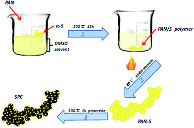
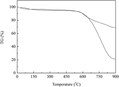
The fabrication process of SPC can be divided into two main steps, as shown in Fig. 1. Firstly, the components of PAN and sulfur were dissolved in organic solvent forming homogenous solution to promote the cross-linking reaction more fully, which was then treated at 200 °C for 12 h to be vulcanized. Two reactions are thought to occur in the vulcanizing process: first, the nitrogen bounds to the carbon in the adjacent nitrile group by cleaving the triple bonds in the nitrile groups to form heterocyclic ring structure. Then some of sulfur in this liquid phase reacted with it, and others were embedded in the ring-like of dehydrogenated PAN. Finally, the vulcanized PAN was carbonized to form final product at high temperature under N2 atmosphere. Taking advantage of vulcanized PAN polymer, the heat treatment would endow the final material with high electric conductivity, excellent dispersion and high contend of entrapped sulfur, which would favor the improvement of electrochemical performance of lithium battery.After carbonization, the black SPC was evaluated for its sulfur content and thermal stability as sulfur base cathode material. For a parallel comparison, the carbonized pure PAN without vulcanization, denoted as PPC, was also analyzed. The results were shown in Fig. 2. As seen here, in the temperature range from 25 °C to 600 °C, both samples exhibited a slight mass loss about 3–5% below 150 °C, which is ascribed to the water evaporation. It was reported that the evaporation temperature of sulfur in micropores was higher than it in the larger voids.16 Further increasing temperature, there was no obvious mass loss for SPC until 600 °C, indicating a strong bonding between sulfur and carbonized PAN by possible effects of vulcanizing reaction or chemisorption of sulfur into SPC driven by high temperature. It was found that the mass loss in such temperature range was about 74% and 25% for SPC and PPC, respectively. Apparently, in comparison to the sample of PPC, the larger mass loss at higher temperature could be ascribed to the sublimation of sulfur species in this PAN-derived carbon support. From the weight balance, the sulfur content was determined to be about 49 wt% in the sample of SPC.
Fig. 3a shows the FTIR spectra of SPC and PPC. Some characteristic peaks were observed for the SPC in relative low wavenumber of 500–1100 cm−1, while these peaks were lack for the sample of PPC. Among them, the peaks at 513 cm−1 and 670 cm−1 were assigned to be the S–S stretching and the C–S stretching in SPC, and the peak at 970 cm−1 corresponded to the ring breathing in which the S–S bond in side chain was contained. This result confirms that the C–S and S–S bonds were formed after the vulcanization reaction, which was consistent with the previous report.17 In addition, the FTIR peaks at 1500 cm−1 and 1250 cm−1 reflected the atomic configuration of carbon support, which were assigned to the C![[double bond, length as m-dash]](https://www.rsc.org/images/entities/char_e001.gif) C and C
C and C![[double bond, length as m-dash]](https://www.rsc.org/images/entities/char_e001.gif) N symmetric stretching, respectively. Comparing to the sample of PPC, the SPC had more intensified peaks at 1500 cm−1 and 1250 cm−1. It indicated that the addition of sulfur contributed the carbon support to higher degree of turbostratic carbon structure during the dehydrogenation step.
N symmetric stretching, respectively. Comparing to the sample of PPC, the SPC had more intensified peaks at 1500 cm−1 and 1250 cm−1. It indicated that the addition of sulfur contributed the carbon support to higher degree of turbostratic carbon structure during the dehydrogenation step.
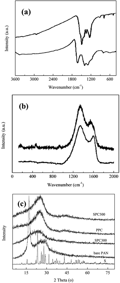 | ||
| Fig. 3 (a) FTIR spectra of SPC (upper) and PPC (lower), (b) Raman patterns of bare PPC (lower) and SPC (upper), (c) XRD patterns of bare PAN, SPC300, PPC, and SPC500. | ||
Fig. 3b shows Raman spectra of PPC and SPC. As seen here, there were three distinctive peaks at 170, 460 and 920 cm−1 on SPC, while these peaks did not appear in the spectra of PPC. It suggested the chemical configuration of SPC changed markedly after the vulcanization reaction. Based on previous reports, the peak at 170 cm−1 was assigned to be the C–S stretch and the peaks at 460 cm−1 and 920 cm−1 were assigned to be the S–S stretch.18 Moreover, it was found from Fig. 4 that the Raman spectrum of SPC and PPC both showed two major peaks at 1350 cm−1 and 1580 cm−1, which corresponded to the disordered D band and the graphitic G band, respectively. Accordingly, the intensity ratios of band G and band D for SPC and PPC were calculated to be 0.83 and 0.55, indicating that the SPC had stronger crystallinity. The result confirmed that the reaction could promote the dehydrogenation and efficient π–π stacking, which favored the formation of graphite carbon configuration.
The XRD analysis can elucidate additional information about the structure evolution at the different synthesis stages. For this purpose, the XRD was performed to measure varied samples of sulfur, bare PAN, PPC, and SPC calcined at 300 and 500 °C, respectively, and the results were shown in Fig. 3c. It can be seen that the pure PAN exhibited a major peak at 2 theta = 17°, which was assigned to be the 110 reflection of PAN crystal structure. Following the conversion of PAN into PPC by calcination, such characteristic peak at 17° disappeared and a relative broad diffraction peak at about 24.4° appeared. According to the previous research (Doan T., 2013), the new generated peak at 24.4° corresponded to the graphitic 002 reflection, confirming that the carbonization of PAN took place under such temperature. From recent studies, the sulfur could be intercalated into the graphene layer when the temperature was above 400 °C.19,20 The SPC obtained at 300 °C showed no characteristic peaks of elemental sulfur were identified compared with XRD spectra of pure sulfur for the sulfur intercalating in the micropores or reacting with polyaniline. Thus, based on the date of TGA, FTIR, Raman spectra, XRD, and electrochemical characters, it could be concluded that, during the vulcanization process, a fraction of elemental sulfur chemically linked with PAN, and the rest of melted sulfur was entrapped in the micropores of the newly formed polymer networks. Moreover, the temperature of calcination affected the carbonization degree of SPC. For example, the significant peak at 25.2° on SPC became enhanced with being treated at higher temperature, which corresponded to the graphite-like π–π stacking of the hexahydric-ring layer of carbonized PAN. Accordingly, the PAN derived carbon materials at high temperature would facilitate excellent electrical conductivity of lithium battery in application process.
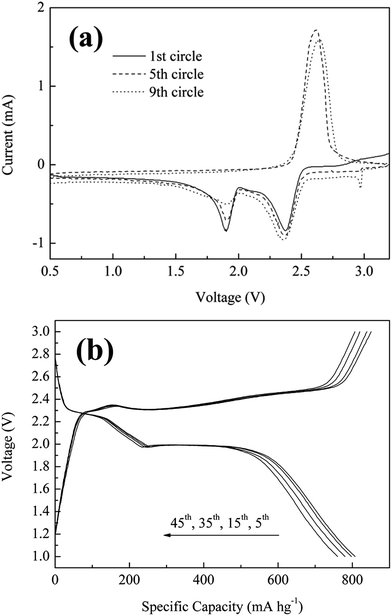
The electrochemical performances of the SPC as cathode material were characterized in coil cells with lithium foil as the counter electrode. Fig. 4a showed three cyclic voltammetry cycles of 1st, 5th and 9th from 0.5 to 3.5 V at a scanning rate of 0.05 mV s−1 for SPC material. The plot shows electrochemical characters typical of the elemental sulfur reaction, indicating that some of sulfur did not bond with carbon backbone because of this peculiar liquid phase reaction. It was found that two reduction peaks positioned around 1.9 and 2.3 V were observed in the first circle, which arose from the electrochemical cleavage and reformation of the sulfur–sulfur bonds of a two-stage reduction reaction from sulfur to long-chain soluble polysulfides (Li2Sn, 4 ≤ n < 8) and further to short-chain insoluble polysulfides (Li2S2/Li2S).21,22 Moreover, a new peak showing at 2.9 V in 9th cycle did not be in accord with the reduction potential plateaus,as reported previously, and we are currently working on finding the reason. Also, an oxidation peak at 2.3 V was identified when scanning in the positive direction, which arose from the oxidation reaction wherein Li2S2/Li2S were involved into a series of chemical reactions to generate long chain polysulfides. Following further cycles, the reduction peaks at 2.3 and 2.0 have their potential shifted slightly toward the negative direction, while the 2.3 V oxidation peak shifted relatively higher potential with slightly reduced peak intensity. Such tiny shift was probably due to the fact that the reaction kinetics had been enhanced with further circle operation.
Fig. 4b showed the distinctive galvanostatic charge–discharge curves for SPC along with varied circles at a low charge/discharge of 0.5C. It revealed that there were two plateaus for discharge stage and one main plateau for charge stage, respectively. These plateaus corresponded to the redox reaction during the discharge–charge process, which were consistent with that of cyclic voltammetry (Fig. 4a). For the SPC with sulfur content of 49% in mass, the reversible discharge capacity at 5th circle was about 1646.9 mA h gsulfur−1, corresponding to 98% of theoretical capacity of sulfur (1670 mA h g−1). After 45 circles, it still remained high discharge capacity of 761 mA h gcomposite−1 or 1553 mA h gsulfur−1. Additionally, the voltage difference between charge and discharge plateaus changed less upon cycling, which indicated that the SPC has both excellent reaction reversibility and high structure stability.
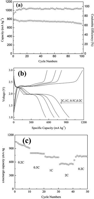
Fig. 5a reported the discharge stability and coulombic efficiency of the SPC cathode under a charge/discharge current of 0.5C. The clear capacity decay could be only found within the first 10 cycles, followed by a relatively stable capacity after 10 cycles. The main reason for the capacity decay during the first 10 cycles could be attributed to the dissociation of superficial sulfur from SPC. It was found that the capacity at 100 cycles was as high as 1414 mA h gsulfur−1, which was 91.3% of the capacity at the 10 cycles, and the average coulombic efficiency of 95% was achieved, indicating the effectiveness of the SPC architecture in sequestering sulfur and inhibiting shutting reaction. Based on the results above, it can be concluded that the SPC possessed high capacity and cycling performance at C-rate of 0.5C. To characterize fully the electrochemical performance of SPC, the rate capabilities and charge/discharge curves of the SPC electrode at different C-rates from 0.2C to 2C were measured and presented in Fig. 5b and c. It revealed from Fig. 5b that the discharge capacity of SPC at low C-rate of 0.2C was determined to be about 952 mA h gcomposite−1 or 1942.8 mA h gsulfur−1, which is higher than the theoretical capacity of sulfur (1675 mA h gsulfur−1). It may derive from the uniform distribution of sulfur in the electrical conducting polymers because of the unique liquid phase reaction system. This ultrahigh capacity was similar with results from the PAN–S composite, as reported previously.23 With increasing the C-rate to 0.5C, and 1C and 2C, the charge/discharge curves showed the same pattern except the discharge capacity decreased gradually to 776, 689 and 548 mA h gcomposite−1, respectively.
The rate capacities and cycle life behavior of SPC is shown in Fig. 5c. It revealed that the discharge capacity decreased gradually in the first few circles at 0.2C and then became stable and decreased regularly with further cycles and higher C-rate. Specifically, when C-rate was switched back from 2C to low C-rate of 0.2C again, the discharge capacity increased up to 726 mA h gcomposite−1, as an indication of excellent recovery of discharge capacity. All these results demonstrated that the SPC has good electrochemical reversibility and structure stability even after fast charging and high current discharging.
Conclusions
In summary, we demonstrated here that the interaction between sulfur and polyacrylonitrile (PAN) in DSMO solvent can be used to generate the sulfur-carbonized PAN (SPC) for lithium battery application. After 100 cycles at a 0.5C rate, the electrode could still retain a very high discharge capacity of 1304 mA h gsulfur−1. We believe such excellent electrochemical activity was induced by this new synthetic methodology. Several factors could be attributed to the excellent overall electrochemical behavior. First, the unique properties of hydraulic reaction provided uniform molecular-level encapsulation of sulfur, which leaded to the high utilization of sulfur. Second, the sulfur could be entrapped in micropores, nevertheless the electrolyte could not reach directly so that the polysulfide dissolution might be altered partly. This new family of vulcanized carbonized material offered great opportunity to fabricate high-performance cathode with low cost.Acknowledgements
The work was funded by Natural Science Foundation of China (grant 21206097, 21476144 and 21676170), Science Foundation for The Excellent Youth Scholar of Sichuan University (grant 2014SCU04A04).Notes and references
- R. Demir Cakan, M. Morcrette, F. Nouar, C. Davoisne, T. Devic, D. Gonbeau, R. Dominko, C. Serre, G. Férey and J. M. Tarascon, J. Am. Chem. Soc., 2011, 133, 16154 CrossRef CAS PubMed.
- P. G. Bruce, S. A. Freunberger, L. J. Hardwick and J. M. Tarascon, Nat. Mater., 2012, 11, 19 CrossRef CAS PubMed.
- S. R. Chen, Y. P. Zhai, G. L. Xu, Y. X. Jiang, D. Y. Zhao, J. T. Li, L. Huang and S. G. Sun, Electrochim. Acta, 2011, 56, 9549 CrossRef CAS.
- J. J. Chen, Q. Zhang, Y. N. Shi, L. L. Qin, Y. Cao, M. S. Zheng and Q. F. Dong, Phys. Chem. Chem. Phys., 2012, 14, 5376 RSC.
- S. Evers and L. F. Nazar, Chem. Commun., 2012, 48, 1233 RSC.
- M. Xiao, M. Huang, S. Zeng, D. Han, S. Wang and L. Sun, RSC Adv., 2013, 3, 4914 RSC.
- X. Wang, X. Fang, X. Guo, Z. Wang and L. Chen, Electrochim. Acta, 2013, 97, 238 CrossRef CAS.
- S. Xin, L. Gu, H. Zhao, Y. Yin, L. Zhou, Y. Guo and L. Wan, J. Am. Chem. Soc., 2012, 134, 18510 CrossRef CAS PubMed.
- N. Jayaprakash, J. Shen, S. Moganty, A. Corona and L. Archer, Angew. Chem., Int. Ed., 2011, 50, 6026 CrossRef.
- M. Park, J. Yu, K. Kim, G. Jeong, J. Kim, Y. Jo, U. Hwang, T. Woo and Y. Kim, Phys. Chem. Chem. Phys., 2012, 14, 6796 RSC.
- K. Lee, R. Black, T. Yim, X. Ji and L. Nazar, Adv. Energy Mater., 2012, 2, 1490 CrossRef CAS.
- G. Li, S. Ye and X. Gao, Adv. Energy Mater., 2012, 2, 1238 CrossRef CAS.
- T. Hwang, D. Jung, J. Kim, B. Kim and J. Choi, Nano Lett., 2013, 13, 4532 CrossRef CAS PubMed.
- J. Guo, Z. Yang, Y. Yu, H. Abruña and L. Archer, J. Am. Chem. Soc., 2013, 135, 763 CrossRef CAS PubMed.
- C. Liang, N. J. Dudney and J. Y. Howe, Chem. Mater., 2009, 21, 4724 CrossRef CAS.
- L. Wang, X. He, J. Li, M. Chen, J. Gao and C. Jiang, Electrochim. Acta, 2012, 72, 114 CrossRef CAS.
- T. Doan, M. Ghaznavi, Y. Zhao, Y. Zhang, A. Konarov, M. Sadhu, R. Tangirala and T. Chen, J. Power Sources, 2013, 241, 61 CrossRef CAS.
- X. Yu, J. Xie, J. Yang, H. Huang, K. Wang and Z. Wen, J. Electroanal. Chem., 2004, 573, 121 CAS.
- E. Z. Kurmeav, A. V. Galakhow, A. Moewes, S. Moehlecke and Y. Kopelevich, Phys. Rev. B: Condens. Matter Mater. Phys., 2002, 66, 193402 CrossRef.
- H. Yang, H. Wen, Z. Zhao and S. Li, Phys. Lett., 2001, 18, 1648 Search PubMed.
- D. H. Han, B. S. Kim, S. J. Choi, Y. J. Jung, J. Kwak and S. M. Park, J. Electrochem. Soc., 2004, 151, 283 CrossRef.
- B. Jin, J. U. Kim and H. B. Gu, J. Power Sources, 2003, 117, 148 CrossRef CAS.
- L. Yin, J. Wang, F. Lin, J. Yang and Y. Nuli, Energy Environ. Sci., 2012, 5, 6966 CAS.
| This journal is © The Royal Society of Chemistry 2016 |

