An overview on dry reforming of methane: strategies to reduce carbonaceous deactivation of catalysts

Shalini Arora and R. Prasad*
Department of Chemical Engineering and Technology, IIT (BHU), Varanasi, India. E-mail: shalini@iitk.ac.in

Received 13th August 2016 , Accepted 21st October 2016

First published on 24th October 2016


Abstract

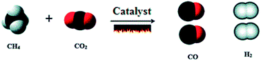
Catalytic reforming of methane (CH4) with carbon dioxide (CO2), known as dry reforming of methane (DRM), produces synthesis gas, which is a mixture of hydrogen (H2) and carbon monoxide (CO). CH4 + CO2 → 2CO + 2H2, ΔH° = 247.3 kJ mol−1, ΔG = 61[thin space (1/6-em)]770–67.32T. The DRM process has gained much attention recently as it reduces greenhouse gases (GHG), CO2 and CH4, in the atmosphere. In addition to reducing GHG, the DRM process produces valuable chemicals (CO + H2), provides a good approach to utilizing biogas and natural gas with a significant amount of CO2, has good capability as a chemical energy transmission system as compared to steam reforming, and finally yields the desired unity H2/CO ratio for Fischer–Tropsch synthesis. The bimetallic Ni-based catalysts supported on Al2O3/TiO2 and promoted with Ce/ZrO2 show remarkable performances in the DRM process. But, carbonaceous deactivation of the catalysts is the major problem faced during this process. Numerous studies have been cited on various aspects of DRM, and some papers are also devoted to reviewing carbonaceous deposition problems and their remedies. However, some lacunae exist, which are highlighted in the present review paper on strategies to reduce the carbonaceous deactivation of catalysts for improved DRM efficiency by appropriate catalyst development, operating conditions, and flow reactor designs. The disposal of spent catalysts falls under the category of hazardous industrial materials and is also required to comply with stringent environmental regulations. Therefore, regeneration and reclamation techniques for spent catalysts have also been discussed.


1. Introduction

Carbon dioxide (CO2) is the most effective greenhouse gas arising from anthropogenic activities, and needs to be reduced in order to counteract global warming and climate change. CH4 is 21 times more potent than CO2 in increasing the atmospheric temperature.1 Dry reforming of methane (DRM) has gained much attention in recent years for its remarkable performance.2 It converts CH4 and CO2 to synthesis gas or syngas (CO + H2), having an H2/CO ratio close to one according to eqn (1).
 
CH4 + CO2 → 2CO + 2H2, ΔH° = 247.3 kJ mol−1, ΔG° = 61[thin space (1/6-em)]770–67.32T kJ mol−1 (1)

Thus, the DRM process not only reduces CH4 and CO2 emissions into the atmosphere, but also converts them to a valuable product, syngas.3 Syngas is a building block for the production of chemicals; it can be used itself as a fuel or utilized in the manufacture of useful value-added products of more interest, such as: hydrogen (H2), methanol (CH3OH), and liquid synthetic motor fuels {gasoline (C5–C12), naphtha (C8–C12), kerosene (C11–C13), and diesel (C12–C22)}, according to eqn (2)–(4), respectively.

 
CO + H2 + H2O → 2H2 + CO2, ΔH° = −41 kJ mol−1 (2)
 
CO + 2H2 → CH3OH, ΔH° = −90.84 kJ mol−1 (3)
 
nCO + (2n + 1)H2 → CnH2n+2 + nH2O, ΔH° = −ve (4)

Eqn (3) and (4) require additional H2 in the reactant synthesis gas feed, in order to adjust the H2/CO ratio for methanol manufacturing or the Fischer–Tropsch synthesis. Although DRM has many environmental and economic incentives, unfortunately, there are no commercial processes for the dry reforming of methane. Industrial application of the DRM process is also limited.4 Indeed, there are two processes of this kind that produce synthesis gas, called Calcor5 and Sparg.6

Various types of catalysts are reported in the literature for the DRM process, such as noble metals, spinels, perovskites, hydrotalcite, pyrochlore, and supported base metals.1,2,7,8 From an industrial point of view, supported nickel is the most appropriate catalyst for the DRM process due to its availability and low cost, but Ni-based catalysts are more susceptible to deactivation in high-temperature reactions than noble metal catalysts.4,5 This situation leads to the need to develop Ni-based catalysts with improved activity and stability. This can be done by using appropriate supports and preparation methods, and adding modifiers, such as alkaline or noble metals. A number of papers have been published on improving the activity and stability of the catalysts, using a bimetallic catalyst (Ni–Co/Al2O3) promoted with Sr or MgO,9 an Ni–Co/glass fiber spinel structure,10 Ni/(Al2O3/ZrO2/Ce2O3/La2O3) modified with K and Li,11 an aerogel catalyst,12 an Rh-promoted Ni catalyst,13 an atomic layer dispersion method,14 and different modified Ni-based catalysts.15–17

Noble metals (Pt, Pd, Ru, Rh, and Ir) have been found to exhibit promising catalytic activity and good coke deposition resistance, but have limited use due to their high cost and low availability. However, several studies have been reported on microwave dielectric heating over a Pt catalyst,18 Ru/Al2O3, and Ru/SiO2,19 and Ru/TiO2.20 Several other approaches have been studied to resist coke deposition, such as activation techniques for the catalyst,21 varying operating parameters (feed composition,22 temperature, and pressure4), and types of reactors used,2,23 such as combined steam-CO2, CH4 reforming,24–26 and tri-reforming of CH4.27–31

A number of MS32,33 and PhD theses34–39 have been approved by different universities on various aspects of DRM, and significant activities on such subjects are also depicted in many patents.40–42 Several review papers have been published on topics related to DRM, such as catalyst development,43,44 influence of process parameters,2 feasibility of the process,4 and coke management.1 But there is still a gap in the literature for a review article solely devoted to strategies to reduce carbonaceous deactivation of the catalysts. Therefore, in an attempt to fill this gap, the present review lists all possible methods to improve the coke resistance of the catalysts.

2. Background

2.1. Sources of CO2

Carbon dioxide (CO2) is a primary greenhouse gas (GHG) emitted from a variety of human activities and natural sources. A huge amount of CO2 is emitted from anthropogenic sources, such as power generation, the transportation sector, and industries. In 2012, CO2 accounted for about 82% of all U.S. greenhouse gas emissions from human activities.45 Carbon dioxide is naturally present in the atmosphere as part of the Earth's carbon cycle in ocean-atmosphere exchange, plant and animal respiration, soil respiration and decomposition, and volcanic eruptions.46 Human activities are altering the carbon cycle, both by adding more CO2 to the atmosphere and by influencing the ability of natural sinks, like forests, to remove CO2 from the atmosphere. The government of India agreed to reduce carbon emission by 30–35% by 2030.

2.2. Sources of CH4

Methane (CH4) is a colorless and odorless gas produced from the digestion of organic matter via the following two ways: (1) fossil fuel-derived CH4 is produced from thousands or millions of years old fossil remains of organic matter that lies buried deep in the ground. (2) Biomethane, on the other hand, is produced from fresh organic matter, which makes it a sustainable source of energy that can be produced worldwide. A large portion of the gas is emitted from the industrial sector, such as refineries, and petrochemical and shale gas production.47–49 It is generally emitted to the atmosphere during production, processing, storage, and distribution, which accounts for the huge amount in the atmosphere. In addition to industries, a large proportion of CH4 is emitted from the exhaust of vehicles and power gensets fueled by compressed natural gas (CNG). Apart from anthropogenic sources, biomethane is produced in a sizable amount from natural sources by bacterial digestion of biomass under aerobic conditions from wetland, rice fields,48–51 terrestrial plants, and cattle and poultry farms.52,53 Furthermore, landfill sites also emit CH4 via anaerobic digestion by methanogenic bacteria. Biomass burning and forest fires emit additional CH4 into the environment.54

In recent years, air pollution has led to increased use of renewable energy sources, in place of fossil fuels. Biogas containing ∼60% biomethane is a popular source of renewable energy. It can be produced from cow dung and other animal waste, kitchen waste, municipal waste, agricultural residue, and water hyacinths. The biogas production methods and their various applications are detailed in a recent review paper.55

Methane is a source of fuel, but if it leaks into the atmosphere, it will warm it by absorbing solar radiation, so it is called a GHG, like CO2. The major contributor of global warming is CO2 (∼60%), while CH4 has a reduced contribution of ∼15%.56 However, CH4 has a higher global warming potential (GWP) than CO2 but a shorter lifetime in the atmosphere of 12 years. Thus, the Intergovernmental Panel on Climate Change (IPCC) assessment report (AR) values of GWP are based on time. The GWPs for CH4 being quoted in AR-5 are 28 on a 100-year basis and 84 over 20 years.47 This means that one ton of CH4 has the same effect as 84 tons of CO2 over 20 years. One exception is the Environmental Protection Agency (EPA) GHG inventory, which uses a 100 year GWP of 21 for CH4.

2.3. Impact of CO2 and CH4

Greenhouse gases transmit shorter wavelength solar radiation to the earth's surface but do not allow longer wavelengths (IR) generated by the hot earth surface to escape. They absorb the radiation then re-radiate it back to the surface as well as to the lower atmosphere. This re-emission results in an increase in the atmospheric temperature, known as the greenhouse effect. CO2 and CH4 are the most effective greenhouse gases. An increase in the atmospheric temperature of 0.24 °C can be visualized from 1987 to 2015 in Fig. 1. Continuation of this global warming trend until the end of the 21st century could increase the atmospheric temperature by around 5.8 °C.1,2 This “global warming” affects human health, climate, the ozone layer, air pollution, the sea level, and agricultural productivity. So, the survival of living beings would be very difficult in the future, if global warming continues to follow the present trend.
image file: c6ra20450c-f1.tif
Fig. 1 Global warming trend from 1980 to 2015 (http://www.skepticalsscience.com).
2.3.1. Human health. A warm atmosphere can lead to more rapid development of dangerous pathogens, allowing infectious diseases like dengue fever, West Nile Virus and Lyme disease, to spread widely.57,58 Viral dengue fever has increased globally by 30-fold during the last 50 years in America. Drinking water and food supplies have also been contaminated due to increased storms, floods, and draughts. A higher temperature is linked to a long allergenic ragweed pollen season. Ragweed is a North American weedy plant that can generate allergic pollen and cause hay fever (inflammation of the mucous membrane lining to nose), and problems associated with asthma.46,47
2.3.2. Climate changes. The climate has become much too warm, causing more natural disasters. Precipitation patterns have also changed: arid and semi-arid regions are becoming drier, while other areas, mid-to-high latitudes, are becoming wetter. Where precipitation has increased, there has been a disproportionate increase in the frequency of the heaviest precipitation events. Warmer water in the oceans pumps more energy into tropical storms, making them stronger and potentially more destructive.58–60 Climate change has worsened the situation over the last few years; localized record-breaking evidence of rainfall, draught, snowfall, and temperature rise has been observed within the past few years. For example, in June 2013, a cloud burst caused heavy rainfall in Uttarakhand (India), resulting in more than 6000 deaths, and thousands of people became environmental refugees; a similar situation was observed in 2014, in the Jammu & Kashmir state, while Marathwada and Vidarbha have been experiencing severe drought over the last three years due to deficient rainfall, and this has further worsened the situation, with a drastic drop in groundwater levels, acute water shortages and severe loss of crops.
2.3.3. Antarctica warming. The growing temperature of the atmosphere is breaking the Antarctica ice shelf, as the Larsen B ice shelf lost a total of 1255 square miles over 35 days in early 2002. A group of gentoo penguins nests on the icy shore of Cierva cove, Antarctica. They need cold weather to survive, and the warm atmosphere has reduced the population of penguins around from 32[thin space (1/6-em)]000 to 11[thin space (1/6-em)]000 in last few years.60,61
2.3.4. Rise of sea level. The temperature rise of the atmosphere causes a rise in the sea level due to melting of icebergs. The rising sea level caused salination of coastal lands and fresh water supplies, resulting in population displacement.47 This change in the availability and distribution of natural resources, especially water, increased the risk of draught and flooding. These types of natural disasters forced people to flee from their homes, making them environmental refugees.
2.3.5. Ozone layer depletion and photochemical smog. The atmosphere has different layers above the sea level. The first layer, just above the sea level, is the troposphere, and the next one is the stratosphere. The troposphere contains ozone, which is responsible for generating photochemical smog in the presence of sunlight, so ozone is called bad ozone here. However, tropospheric ozone production is increasing because plants absorb less ozone under the present growing conditions.62,63 On the other hand, the stratosphere contains an ozone layer, which protects us from UV radiation, called good ozone, but this ozone layer is continuously depleting, creating a hole. This is because ozone is destroyed by free radical catalysts, such as hydroxyl radicals, nitric oxide radicals, and chlorine atoms.

3. Overview and comparison of different reforming technologies

3.1. Overview

The CH4 reforming processes for the production of synthesis gas are as follows:64 dry reforming of methane (DRM), steam reforming of methane (SRM), partial oxidation of methane (POM),31 combined reforming of methane (CRM/DRM + SRM),26 auto-thermal reforming of methane (ATR/SRM + POM), and a combination of all the three previous processes called tri-reforming of methane (TRM). The heats of reaction in the standard state for the various processes are mentioned below:

Methane dry reforming is an endothermic process and requires energy input to sustain the reaction (eqn (1)):

 
CH4 + CO2 ↔ 2CO + 2H2, ΔH° = 247.3 kJ mol−1 (1)

Steam reforming of methane is also an endothermic process and requires energy input to sustain the reaction (eqn (5)):

 
CH4 + H2O ↔ CO + 3H2, ΔH° = 206.8 kJ mol−1 (5)

Alternatively, syngas can be obtained by exothermic CH4 partial oxidative reforming, according to the following reaction (eqn (6)):

 
CH4 + ½O2 → CO + 2H2, ΔH° = −35.6 kJ mol−1 (6)

Combined dry and steam reforming of CH4 is an endothermic process and requires energy input to sustain the reaction (eqn (7)):

 
3CH4 + 2H2O + CO2 ↔ 4CO + 8H2, ΔH° = 660.9 kJ mol−1 (7)

Auto-thermal reforming (ATR) (eqn (8)) is mildly exothermic to maintain the sustainability of the heat losses during the process:65

 
7CH4 + 3O2 + H2O → 7CO + 15H2 + CO2, ΔH° = −6.8 kJ mol−1 (8)

Tri-reforming of methane (DRM + SRM + POM)31 is an endothermic process that eliminates the individual disadvantages of the above three processes and increases the catalyst life as well as the process efficiency (eqn (9)):

 
20CH4 + H2O + 9O2 + CO2 → 21CO + 41H2, ΔH° = 12.9 kJ mol−1 (9)

Recent laboratory studies with pure gases have shown that the addition of oxygen to CO2 reforming or the addition of oxygen to steam reforming of CH4 can have some beneficial effects in terms of improved energy efficiency or synergistic effects in processing and in mitigation of coking.

3.2. Comparison

The steam reforming of methane (SRM) requires a high heat supply and produces products with a H2/CO ratio of ∼3[thin space (1/6-em)]:[thin space (1/6-em)]1, which is relatively higher than that desired for the Fischer–Tropsch synthesis. Carbonaceous deactivation problems are also associated with this method. But if SRM and DRM are combined, this results a significant decrease in carbonaceous deactivation. In addition, POM is partial oxidation of methane, which is an exothermic process, so it would be more economical than SRM, and the process can be utilized without catalyst. The produced syngas with a H2/CO ratio of 2[thin space (1/6-em)]:[thin space (1/6-em)]1 is ideal for downstream F-T processes. However, POM requires a costly air separation plant for the O2 supply and special equipment for reaction temperatures as high as 1200 K.65 Moreover, the ATR reactor, in comparison to that used for SRM, is moderate in cost, size, and weight requirements. The main drawback is that a relatively extensive control system is needed for ATR, to ensure proper robust operation of the fuel-processing system. Tri-reforming of methane (TRM) is a synergistic combination of endothermic CO2 reforming (eqn (1)), steam reforming (eqn (5)), and exothermic partial oxidation of methane (eqn (6)). Chunshan et al. in 2004 (ref. 31) showed that the combination of dry reforming with steam reforming can achieve two important goals: to produce syngas with desired H2/CO ratios and to alleviate the carbon formation problem that is significant for dry reforming. Combining steam reforming and partial oxidation with CO2 reforming could significantly reduce or eliminate carbon formation on reforming the catalyst, thus increasing the catalyst life and process efficiency. Therefore, the proposed TRM can solve two important problems that are encountered in individual processing. But control of all the three feeds (H2O, CO2, & O2) together is a big issue in TRM as an unbalanced feed can result in the opposite effect on the catalysts.

In comparison to SRM, POM, ATR, and TRM, DRM has unique advantages because of its novelty in the utilization of CO2, which offsets the increasing GHG emissions.

4. Dry reforming of methane

DRM was first studied by Fisher and Tropsch in 1928 over Ni and Co catalysts. It has been of interest for a long time, but in recent years, the interest in DRM has escalated because of environmental concerns and commercial importance. This process has considerable advantages: (i) it is an attractive route toward CO2 mitigation, (ii) methane conversion, and (iii) a H2/CO ratio of approximately unity due to simultaneous occurrence of the reverse water gas reaction (RWGR), as shown by eqn (10).
 
CO2 + H2 → CO + H2O, ΔH° = −41.2 kJ mol−1, ΔG° = −8545 + 7.48T kJ mol−1 (10)

4.1. Thermodynamics

The need for high external heat and a long conversion time (slow reactions) hinder the industrial application of the DRM process.66 Furthermore, carbon deposition is also a major problem in the DRM process. Carbon deposition is significantly affected by the process thermodynamics and is likely to occur by two ways: (i) methane decomposition and (ii) Boudouard reaction. These reactions deactivate the catalyst by blocking catalyst active sites.

A reaction is thermodynamically favourable when the Gibbs free energy is negative (ΔG < 0). Studies of thermodynamic equilibrium67 are usually done by the ΔG minimization method to understand and optimize the DRM variable combinations, such as temperature, pressure, and different feed product ratios.

The progress of a reaction is analyzed by observing the change in the extent of reaction (α) with respect to different operating parameters (temperature, pressure, and feed ratio). The equilibrium constant (in terms of partial pressure), Gibbs free energy, reaction temperature, pressure, mole fractions, stoichiometric ratio, and the gas constant are Kp, ΔG°, T, P, y, ν, and R respectively. Then, the thermodynamic relationship is defined as:

Kp = Π(yiP)νi = exp(ΔG°/RT) = F(α) as fraction yi = (ni0 + νiα)/(n0 + να), where ni0 and n0 are the number of moles of the ith species and the reaction, respectively. Thus, to observe the effect of the operating parameters on the reaction, the change in α needs to be analyzed.

dα/dY = CF(α)/F′(α), (Y can be T or P)

For temperature: C = ΔH/RT2 (if C is positive as for endothermic reactions, then the reaction is favored as temperature increases, and the opposite in the case of exothermic reactions).

For pressure: C = −ν/P (if C is positive, as for a reaction with decreasing moles, then the reaction is favored as pressure increases, and the opposite in the case of increasing moles).

As F(α) depends on the feed moles or feed ratios, the optimum feed ratio can be calculated, which enables the reaction to be spontaneous.68

The DRM reaction is favored at high temperatures (endothermic reaction, positive C) and low pressures (increasing moles reaction, ν = 2). The Gibbs free energy value for the DRM reaction is positive at temperatures below 643 °C (eqn (11)) thus the reaction is not spontaneous at lower temperatures.3

 
CH4 + CO2 → 2CO + 2H2, ΔG = 61[thin space (1/6-em)]770–67.32T kJ mol−1 (11)
at T = 643 °C, ΔG° = +104.88 kJ mol−1, at T = 647 °C, ΔG° = −164.4 kJ mol−1.

The mechanism accepted for coke formation on the catalyst's surface during DRM67 involves two side reactions (methane decomposition: eqn (12); Boudouard reaction: eqn (13)).

 
CH4 ↔ C + 2H2, ΔH° = 75 kJ mol−1, ΔG = 2190–26.45T kJ mol−1 (12)
 
2CO ↔ C + CO2, ΔH° = −171 kJ mol−1, ΔG = −39[thin space (1/6-em)]810 + 40.87T kJ mol−1 (13)

The equilibrium constant for the above reactions is given as image file: c6ra20450c-t1.tif. Ginsburg et al.66 postulated that if K12 > α and K13 > β, then coke formation would be thermodynamically favored, as this would establish that the reactions (eqn (12) and (13)) had not yet reached thermodynamic equilibrium from the side that promotes coke formation,66 where α = (pH22/pCH4)/P0, β = (pCO2/pCO2)/P0, P0 = 105 Pa, and p = partial pressures.

4.2. Kinetics

Reversible reactions involve two reaction rates, the forward and the reverse, rf and rr, respectively, with corresponding activation energies that are determined through the k0, the reaction rate constant. The Arrhenius form relates the thermodynamics to the kinetics and defines the equilibrium constant K that correlates with the absolute temperature T and with the activation energy Ea, while k0 is the pre-exponential factor, and R is the universal gas constant (eqn (14)–(16)).

Arrhenius form:

 
k = k0[thin space (1/6-em)]exp(−Ea/RT) (14)

Forward reaction rate constant:

 
rf = kf(CA,CB), kf = k0f[thin space (1/6-em)]exp(−Ea/RT) (15)

Reverse reaction rate constant:

 
rr = kr(CR), kr = k0r[thin space (1/6-em)]exp(−Ea/RT) (16)
where CX (X = A, B, or R) is the component concentration and k0 is the frequency factor, as determined by the Arrhenius law.

The equilibrium constant K will be expressed as the ratio of the above rates: K = kf/kr.

The equilibrium constant K determines the extent to which the DRM reaction occurs.67 The reactions cannot be shifted to the opposite side by changing the molar ratio of reactants when K is much higher than 1,66 but for K in the vicinity of 1, varying the molar ratio of the reactants has considerable influence on the distribution of the products. Whenever, ΔEa is negative in the DRM, a larger ln(K) indicates that a spontaneous reaction is more feasible.

4.3. Carbonaceous deactivation

Methane decomposition occurs at temperatures above 557 °C and the Boudouard reaction at temperatures below 700 °C. Thus, maximum carbon deposition is reported in the temperature range 557–700 °C, as shown in the equilibrium data for the DRM reaction (Fig. 2).
image file: c6ra20450c-f2.tif
Fig. 2 Equilibrium data for DRM process.44

Each total pressure value (shown on each line in Fig. 3) has a particular temperature, above which no carbon formation is reported with respect to the CH4/CO2 feed ratio, as revealed in Fig. 3.44 At atmospheric pressure, carbon formation will be below 870 °C. Fig. 2 and 3 suggest that the temperature range for the DRM process should be 643–1027 °C and the pressure close to atmospheric.4,44


image file: c6ra20450c-f3.tif
Fig. 3 Thermodynamic analysis of total pressures, temperatures, and feed ratios for carbon formation.44

Different types of carbon species are deposited during the DRM process, such as Cα, Cβ, Cγ, Cv, and Cc (for nomenclature see Table 1). For example, CO and CH4 dissociate at the catalyst surface and give Cα, an adsorbed atomic carbon. This reacts to give Cβ, polymeric amorphous films that again react to give Cγ, Cv, and Cc.69 These points are clearly shown in Fig. 4 and Table 1, giving details about these different forms of carbon with their respective temperature changes.

Table 1 Details of different carbon species formed on the catalyst surface
Carbon structure Designation Temperature range (°C)
Adsorbed, atomic carbon (surface carbide) Cα 200–400
Polymers, amorphous films Cβ 250–500
Ni carbide (bulk) Cγ 150–250
Vermicular filaments or whiskers Cv 300–1000
Graphite (crystalline) platelet films Cc 500–550


image file: c6ra20450c-f4.tif
Fig. 4 Mechanism of carbon formation at the catalyst surface.

It should be emphasized that some forms of carbon decrease the activity of the catalyst and some do not. For example: Cβ at temperatures <300–400 °C and Cc at temperatures >650 °C encapsulate the metal surface of the catalyst. At high temperatures, (500–900 °C) the carbidic form of atomic carbon mixed in Ni surface layers to a depth of more than 50–70 nm. If this accumulates at high or low temperatures, adsorbed carbon can deactivate the metal active sites.69 The phenomenon of carbon deposition on the catalyst surface is shown in Fig. 5.


image file: c6ra20450c-f5.tif
Fig. 5 Pore plugging in a supported metal catalyst owing to carbon deposition.69

5. Strategies to reduce carbonaceous deactivation of catalysts

5.1. Development of catalysts

5.1.1. Active species of catalysts. Active metal species used in catalysts are divided into two categories: base metals and noble metals. Generally, Ni is used as the active species for DRM catalysts due to its high activity and low cost. Some other metals, such as Co or noble metals, are added to examine bimetallic effects on the catalysts. Noble metals (Ru, Rh, Ir, Pd, and Pt) have high activity and low sensitivity for carbon deposition.2
5.1.1.1. Base metal catalysts. Industrially, the metal of choice for the catalyst is nickel due to its inherent availability and lower cost in comparison to other more noble metals. However, because the reforming reaction is strongly endothermic, equilibrium yields of synthesis gas require high temperatures and, under such reaction conditions, several studies with alumina-supported metals70,71 have shown that nickel is more susceptible to coking than noble metals; regardless of this, economic and availability constraints typically prohibit the use of noble metal catalysts on an industrial scale, and it is still worthwhile to pursue the development of supported nickel catalysts.

Recently, core–shell catalysts, especially metal@silica, have been much investigated due to their unique physico-chemical properties, which can efficiently inhibit sintering of the active metal and prevent carbon deposition. Supported Ni catalysts with core@shell structures offer lower internal diffusion resistance, since metal nanoparticles forming the shell are not buried in the support framework, such as the silica core. Metal particles in a core@shell structure usually have strong chemical and physical interactions with the support matrix and thus are highly resistant to sintering and deposition. The core@shell structure of catalysts may also allow reduction of the amount of metal used, since the core does not contain metals.72 Core@shell catalysts can be synthesized by a number of different techniques, which include: the deposition–precipitation method, ultrasonic treatment of the support and a nickel salt solution, sol–gel/reduction method, and reduction with a previously prepared core or by a sequential reduction process.

Lim et al. also synthesized Ni@ZrO2 (ref. 73) with this route, and this showed a good catalytic performance and carbon resistance. Most recently, Bian and coworkers,74 2016, synthesized a multicore–shell of Ni–Mg phyllosilicate nanotubes (PSNTS) coated with a layer of mesoporous silica with a thickness of ∼10 nm by a modified Stöber method of hydrolysis of TEOS in an ethanol solution mixed with ammonia and cetrimonium bromide (CTAB). The authors reported that multiple small Ni particles were observed supported along the nanotube, as well as encapsulated by the silica shell on reduction by H2 at high temperatures. They claimed that the reduced catalyst showed a high and stable conversion for DRM during a 72 h durability run at 750 °C, and much improved carbon resistance compared to the uncoated sample, which decomposed at such a high temperature.

Although the study of metal core–shell catalysts has only started a few years ago, these have exhibited great potential for application in heterogeneous catalysis, owing to their high activity, high stability, high selectivity, and other functions. Despite the great advancements in this field, several problems remain unsolved, which are listed as follows: (1) the efficient fabrication methods of the core–shell structural catalyst are still limited, and each method can only be used to prepare certain materials. (2) The core size and the shell thickness remain difficult to control precisely. (3) The yield of the core–shell catalyst remains low. (4) When a metal core is used as the active part of the catalyst, its catalytic activity is always degraded by the shell-block effect. These facts have restricted the application of the core–shell structure material; meanwhile it offers a lot of scope for the extension of the fabrication of core–shell catalysts.

Table 2 listed details of some published works based on base metal catalysts for the DRM process. Ni/CeO2, Al2O3,75 Ca, Ce-promoted Ni–Ce/SBA15,76 and 3% Ni/γAl2O3 (ref. 77) result in high conversion and low carbon deposition due to the high oxygen-storing capacity of Ce. Ni–Co catalysts9,10 also show a remarkable performance with a Sr promoter and glass fibre support.

Table 2 Base metal catalyst performances for the DRM process
Reference Catalyst Rxn parameter Specific finding Remarks
Fatesh (9) 5% Ni–5% Co/Al2O3 promoter 0–1% Sr, IM at 80 °C/5 h CO2/CH4/N2 = 17/17/2, P = 1 atm, T = 500–700 °C, 0.6 g Cat, F/W = 60 ml min−1 gcat−1 Opt T = 700 °C, XCH4 = 84.9%, XCO2 = 82.3% 0.75% Sr gives best results
Talkhoncheh & Haghighi (75) Ni nano catalyst on clinoptile, CeO2, Al2O3 IM CH4/CO2 = 1[thin space (1/6-em)]:[thin space (1/6-em)]1, T = 550–850 °C, flow rate = 30 cm3 min−1, Cat = 0.1 g Opt T = 850 °C, XCH4 = 93%, XCO2 = 96%, H2/CO = 0.91 Alumina gives good results
Albazari et al. (76) Ni–Ce/SBA-15 5% Ni–5% Ce, IM first Ce then Ni CH4/CO2 = 1[thin space (1/6-em)]:[thin space (1/6-em)]1, T = 650 °C, P = 1 atm, flow rate = 100 ml min−1 XCH4 ≅ 100%, XCO2 ≅ 90% H2/CO ≅ 1 Ce/Ni < 0.04 prevents pore blocking
Ruckenstein & Hu (11) Ni/alkaline earth metal oxides (MgO, SrO, BaO) IM CH4/CO2 = 1[thin space (1/6-em)]:[thin space (1/6-em)]1, T = 790 °C, P = 1 atm, GHSV = 60[thin space (1/6-em)]000 cm3 h−1 gcat−1 Reduced (H2) XCH4 ≅ 91%, XCO2 ≅ 98% NiO/MgO is best catalyst
Ismagilov et al. (10) Ni–Co/glass fiber by solution combustion CH4/CO2 = 1[thin space (1/6-em)]:[thin space (1/6-em)]1, T = 750 °C, flow rate = 60 cm3 min−1 XCH4 ≅ 90%, XCO2 ≅ 100% 0.4Co–0.4Ni giving 0.13% carbon
Al-Fatesh et al. (77) 3% Ni/γAl2O3 promoted by Ca, Ce, Imp method CH4/CO2 = 1[thin space (1/6-em)]:[thin space (1/6-em)]1, Temp = 850 °C, press = 1 atm, Cat = 0.75 g, F/W = 2640 ml h−1 g−1 XCH4 ≅ 94.1%, XCO2 ≅ 98.3% For 0.15% Ce, 0.05% Ca coke formation <1.5%
Mingjue Yu et al. (78) NixMg1−xO promoted by Sn, Ce, Co, Mn CH4/CO2 = 3[thin space (1/6-em)]:[thin space (1/6-em)]1, T = 760 °C, P = 1 atm, GHSV = 20[thin space (1/6-em)]000 ml h−1 gcat−1 XCH4 ≅ 73%, XCO2 ≅ 90% Ni0.10Mg0.90O catalyst gives <3.48% coke with Co


Bimetallic catalysts. It has been also reported that the combination of nickel and cobalt catalysts reduces carbon deposition in CO methanation, partial oxidation of methane to synthesis gas, and steam or dry reforming of methane.9 The suppression of carbon deposition by the addition of cobalt to a nickel catalyst for CO methanation could be due to an enhancement of the hydrogenation of atomic carbon and/or inhibition of the formation of carbide species in the metal crystal.

A suitable Co[thin space (1/6-em)]:[thin space (1/6-em)]Ni ratio strongly affects the performance and stability of the catalyst. Deactivation would occur due to oxidation of the metals, if the cobalt loading is too high, whereas deactivation could be caused by coking, if the nickel loading is too high. Using a TiO2-supported catalyst under high pressure (2 MPa), Nagaoka et al.20 suggested that 90% of cobalt combined with 10% nickel in 0.05 wt% Co–Ni/TiO2 is the best combination to provide a highly stable catalyst. A Ni–Co catalyst gives better results compared to a monometallic catalyst (Table 3) due to the synergistic effect of Ni–Co metals.16

Table 3 Comparison of conversions given by monometallic and bimetallic catalysts
Al2O3-supported catalyst 500 °C 600 °C 700 °C
CH4% CO2% CH4% CO2% CH4% CO2%
10 wt% Ni 18.2 26.7 50.7 56.3 81.7 83.8
5 wt% Ni + 5 wt% Co 23.8 27.8 57.2 58.8 86.1 84.5


Zhang et al.79 developed a bimetallic Co–Ni catalyst over Al–Mg–O supports by co-precipitation methods with a high calcination temperature, which resulted in NixMg1−x Al2O4 and CoxMg1−x Al2O4 spinel-like80,81 structures and strong metal–support interactions. This method also facilitated a small metal particle size of the reduced precipitate. The combined use of Al and Mg oxides provided the catalyst with not only a relatively high surface area, but also thermal stability. Perovskite-type catalysts82,83 have also been studied, both alone and incorporated with nickel as a transition metal, which resulted in highly coke-resistant catalysts.


5.1.1.2. Noble metal catalysts. Thermodynamic analysis shows that DRM requires reaction temperatures as high as 900 °C to attain high syngas yields. Even though not thermodynamically favored at high temperatures, the reaction is inevitably accompanied by carbon deposition. At these high temperatures, supported metal catalysts are prone to deactivation due to sintering or irreversible reaction with the support, e.g., forming inactive spinels.80

The properties of noble metals responsible for high activity and low carbon deposition are as follows:63,84

(1) Good dispersion ability in the form of nanoscale particles promote dissociative adsorption of H2/O2.

(2) More exposure of d-subshell electrons.

Souza et al.85 showed that Pt–Al deactivated quickly during the first 20 h of CH4–CO2 reforming at 1073 K, while zirconia-based catalysts (with ZrO2 content >5%) presented improved stability over the course of 60 h. In another case, a combination of Rh–Ni supported on boron nitride (BN) has shown higher DRM activity, as well as stability with respect to deactivation compared to Rh–Ni on γ-Al2O3 (Table 4).

Table 4 Noble metal catalysts for DRM process
Reference Catalyst Reaction parameters Specific findings Remarks
Aparicio et al. (19) Ru/Al2O3, SiO2 IM CH4[thin space (1/6-em)]:[thin space (1/6-em)]CO2[thin space (1/6-em)]:[thin space (1/6-em)]He = 10[thin space (1/6-em)]:[thin space (1/6-em)]10[thin space (1/6-em)]:[thin space (1/6-em)]80, flow rate – 100 ml min−1, T = 823 K, 1023 K 823 K, Ru/SiO2, XCH4 ≅ 12%, Ru/Al2O3, XCH4 ≅ 14%, 1023 K, Ru/SiO2, XCH4 ≅57%, Ru/Al2O3 XCH4 ≅52% Less activity loss for Al2O3 than SiO2
Bitter et al. (87) Pt/ZrO2 Rh/Al2O3, ZrO2 IM CH4[thin space (1/6-em)]:[thin space (1/6-em)]CO2[thin space (1/6-em)]:[thin space (1/6-em)]Ar[thin space (1/6-em)]:[thin space (1/6-em)]N2 = 42[thin space (1/6-em)]:[thin space (1/6-em)]42[thin space (1/6-em)]:[thin space (1/6-em)]75[thin space (1/6-em)]:[thin space (1/6-em)]10, T – 873 K, flow rate – 170 ml min−1 Pt/ZrO2, Rh/Al2O3, Rh/ZrO2 comparable catalysts w.r.t. activity and stability Rh/Al2O3 more active than Pt/ZrO2, Rh/ZrO2
Souza et al. (85) Pt/ZrO2, Al2O3 IM CH4[thin space (1/6-em)]:[thin space (1/6-em)]CO2[thin space (1/6-em)]:[thin space (1/6-em)]He = 1[thin space (1/6-em)]:[thin space (1/6-em)]1[thin space (1/6-em)]:[thin space (1/6-em)]18, flow rate = 200 cm3 min−1, T = 723–1123 K Activity order Pt/10 Zr > Pt/5Zr > Pt/20Zr > Pt/Al at 1023 K, XCH4 ≅80%, XCO2 ≅ 91% Pt/ZrO2 has less carbon; more stable than Pt/Al2O3
Perera et al. (88) 5% Ru/Eu2O3, IW CH4[thin space (1/6-em)]:[thin space (1/6-em)]CO2[thin space (1/6-em)]:[thin space (1/6-em)]He = 1[thin space (1/6-em)]:[thin space (1/6-em)]1[thin space (1/6-em)]:[thin space (1/6-em)]6, T = 973 K XCH4 ≅ 92%, XCO2 ≅ 90% No sign of coke formation


The ratio of promoter to the active metal is also as crucial as the synthesis procedure in the stable operation of the DRM catalyst. Ballarini et al.86 studied Na, K, and Mg-promoted catalysts for 0.02% Pt/Al2O3, 0.1% Pt/Al2O3, and 0.5% Pt/Al2O3. They observed that 0.02% Pt/Al2O3 promoted with K or Na showed no observable activity, while promotion with Mg showed CH4/CO2 conversion greater than for K or Na-promoted 0.02% Pt/Al2O3. Similarly, 0.1% Pt promoted with Mg showed higher activity than the same catalyst promoted with K and Na, although all three catalysts showed deactivation.

The Ru and Rh showed the best resistance among the noble metals,89 toward catalyst deactivation by carbon deposition. Numerous studies in the last few decades compared the activities of the noble metals in order to determine which noble metal performs best with respect to activity and resistance to carbon deposition. Hou et al. compared the stability and reactivity of Rh (5 wt%), Ru (5 wt%), and Ni (10 wt%) as supported metals. The noble metals showed higher coke resistance ability, while their activity was relatively low in comparison to Ni. In comparison to Ru, the Rh in this study presented higher dispersion on the mesoporous Al2O3 and exhibited higher coke resistance and higher reforming activity.

5.1.2. Catalyst particle size and metal loading. A number of published papers are devoted to clarifying the relationships between carbon deposition on Ni catalysts and metal particle size, and loading percentage. Crnivec et al.16 and Wang et al.90 both studied the DRM process performance with respect to different metal loadings and catalyst particles. Crnivec examined this behaviour over Ni–Co/CeO2 and ZrO2 catalysts and Wang90 over metal-supported catalysts. Four catalysts having metal (Ni–Co) loadings of 3, 6, 12, and 18% were prepared and examined in a CH4–CO2-reforming reaction.16 A considerable amount of accumulated carbon was formed with a Ni–Co loading greater than 12%. As the amount of metal loading increased, significant growth of the bimetallic particle was induced, thus indicating the existence of strong metal/support interactions at low active metal loadings. Similar observations were also reported for CH4 conversion during the DRM process (Fig. 6).90
image file: c6ra20450c-f6.tif
Fig. 6 Effect of metal loading on CH4 conversion at different temperatures.90

A positive correlation between the average particle size and carbon accumulation is mentioned, in which small particles favour the initial activation of methane, whereas larger clusters enable stable long-term methane decomposition, producing carbon nano-filaments. Catalysts containing active metal particles smaller than 6 nm exhibit superior resistance to carbon accumulation on catalyst surfaces and display a certain selectivity for the RWGS reaction.16 Catalysts with a large metal particle size simulate the occurrence of the methane dehydrogenation reaction and consequently accumulate a considerable amount of carbon on their surface. Gohier et al.91 investigated the carbon nanotube growth mechanism with catalyst particle size. They observed that a small crystallite size (<5 nm) stimulates the growth of single-walled and few-walled carbon nanotubes that grow from the particle outwards, whereas larger crystallite sizes (>15 nm) are capable of forming multi-walled nanotubes that grow from beneath the particle.

5.1.3. Catalyst supports. A catalyst is composed of two individual elements: the active metal species and the support, which acts as a mesoporous substrate on which metal is dispersed. Mesoporous nanostructured materials have been studied extensively for the design of heterogeneous catalysts for the application of catalytic reforming, due to their high surface area and low density.92 Carbon deposition on the catalyst surface is affected by the support basicity, and it has been observed that carbon formation can be reduced by introducing Lewis basicity to the support.93 The nature of the oxide support greatly affects the catalyst activity due to the varying active surface area and acid base properties. Carbon dioxide reforming involves the adsorption and dissociation of CO2 on catalysts. Since CO2 is well-known as an acidic gas, a highly basic support may result in a significant increase in adsorption of CO2, resulting in high activity towards CO formation and a lower possibility of carbon formation or high stability.94

Great efforts are made to maximize the catalyst surface area by better dispersion of active metal over the mesoporous support. The catalyst surface area gives space for the reaction to occur; while the whole area is not used for reaction, but has some specific active sites that are responsible for the reaction. A high surface area increases the probability of these active sites and results in high catalytic activity.

Table 5 describes the catalytic activity on different supports. Specifically, Al2O3 and TiO2, with high basicity, provide the most stable performance in the DRM process. Yttria-stabilized zirconia (YSZ) also promotes high activity, but is experimentally verified for noble metals only. Over the Rh/YSZ catalyst, it is found that there exists a lattice oxygen species of the carrier, which intensively interacts with CO2. A spillover of these lattice oxygen species onto the Rh surface contributes to the formation of CO and H2O.95 The different turnover rates are also correlated with the stabilized species of Rh atoms. It is thus concluded that the supports can influence the electronic state of Rh atoms, and that Rh metal serves as a prominent active species in the reforming reactions.96–98

Table 5 Catalyst activity on different supports
Activity order per active metal Reforming temp, K Metal loading wt, % Ref.
Rh
Al2O3 > TiO2 > SiO2 773 0.55 97
Al2O3 > TiO2 > SiO2 773 0.5 98
TiO2 > La2O3 = CeO2 > ZrO2 = MgO = SiO2 = MCM-41 > γ-Al2O3 973 0.5 94
Yttria-stabilized zirconia (YSZ) > Al2O3> TiO2 > SiO2 > La2O3 > MgO 873 0.5 95
[thin space (1/6-em)]
Ru
YSZ ≫ SiO2 > TiO2 > ZrO2 > γ-Al2O3 700 0.51–0.64 99
[thin space (1/6-em)]
Pt
TiO2 > Al2O3 > SiO2 723 4 100
[thin space (1/6-em)]
Mo2C (molybdenum carbide)
Al2O3 > SiO2 > ZrO2 > TiO2 1220 3.8 101
[thin space (1/6-em)]
Ni
γ-Al2O3 > TiO2 > ZrO2-CP > ZrO2-AS > SiO2 1073 5 102
La2O3–SiO2 > α-Al2O3–MgO > CeO2 > TiO2 973 5 94


5.1.4. Catalyst promoters. The catalyst promoters are non-active materials that are recommended to improve the catalytic performance through surface structural effects. Promoters improve the active metal species dispersion over the support,103 due to the existence of a strong metal–support interaction effect, which increases the basicity of the catalysts. It also supports the gasification of accumulated carbon. Ag-Promoted catalysts alter the type of coke formed on the catalyst surface from whisker to amorphous species.104

Zapata et al.105 studied the promoting effect of Ca, K, and Ce on the activity of Ni/SiO2 catalysts for the methane decomposition reaction. They reported that Ce greatly increased the conversion of methane and improved the stability, while catalysts promoted with K and Ca were less active and stable than the Ni/SiO2 catalysts.

Al Fatesh et al.106 studied the effect of promoters on methane dry reforming over Ni catalysts supported on mixed α-Al2O3 + TiO2-P25 (Table 6). The results for catalyst stability and activity showed that the Zr promoter with Ni provided the best catalyst activity for CH4 and CO2 conversions.77

Table 6 Comparison of unpromoted and Ce, Zr-promoted catalyst performance
Promoter Add (wt%) CH4% CO2% Average H2/CO
No promoter 0.0 72.6 75.9 0.98
Ce 0.05 72.3 75.4 0.98
0.15 71.7 73.3 0.97
0.3 68.7 73.6 0.97
Zr 0.05 76.5 74.4 1.06
0.15 77.7 75.9 1.04
0.3 73.6 73.6 1.02


5.1.4.1. Metal oxide promoters. ZrO2 is considered as a promoter when added to the catalyst in small amounts and receives the highest interest among the other metal oxide promoters. Therdthianwong et al.107 concluded that Ni/Al2O3 catalyst deactivation was inhibited by ZrO2 addition. The ZrO2 promoter enhanced the dissociation of CO2-forming oxygen intermediates near the contact between ZrO2 and Ni, where coke deposits were gasified afterwards. MgO and CeO2 are also studied for the DRM process and the results improved the catalytic activity.
5.1.5. Catalyst preparation method. Catalyst preparation methods are very diverse and each catalyst may be produced via different routes. The catalytic properties of heterogeneous catalysts are strongly affected by every step of the preparation, together with the quality of the raw materials. The choice of a method for preparing a given catalyst depends on the physical and chemical characteristics desired in the final composition.108 It is easily understood that the preparation methods are also dependent on the choice of the basic materials. Both unsupported and supported types of catalysts are used for the DRM process.
5.1.5.1. Sol gel method. The sol–gel process is a method used to produce mixed metal oxide catalysts. The process involves conversion of monomers into a colloidal solution or reactive state (sol) and poly-condensation of an activated molecular precursor into nanoclusters, with the inherent advantages of molecular-scale mixing of constituents and homogeneity of the sol–gel products.12 La–Co–Ni–Sr–O-based perovskite-type109 and NiAl2O4 spinel-type81 unsupported catalysts prepared by the sol gel resin method are reported for the DRM process. Doping quantities of Sr promote the in situ reduction at lower temperatures, producing Ni0 and Co0 active species with sizes of the order of nanometers, highly dispersed on the La2O2CO3 and SrO matrix, giving rise to very active catalysts for the dry reforming of methane and inhibiting coke formation, in spite of the severe reaction conditions used.81

Zhigang Hao et al.12 investigated DRM through a nanosized aerogel catalyst (Ni/Al2O3) in a fluidized bed reactor. Chen et al.110 described a Ni/CeO2–Al2O3 catalyst prepared by two methods, using the same procedure but a different post treatment, called aerogel and xerogel catalysts. Their results showed that aerogel catalysts are more thermally stable than xerogel catalysts. The aerogel catalyst exhibited a high specific area, a low bulk density, a smaller metal particle size, a stronger metal interaction, and higher metal dispersion, compared to xerogel catalysts. All tested aerogel catalysts showed better activity and stability than impregnated catalysts. Catalytic activity depends on metal loading. Aerogel catalysts gave a low rate of carbon deposition and allowed fluidization with excellent physicochemical properties.

Thus, catalytic activity is directly proportional to metal–support interactions and surface area, and inversely proportional to the metallic catalyst particle size and bulk density. Of these, the metallic particle size and metal–support interactions affect the activity the most. The sol–gel method results in strong metal–support interactions and a smaller particle size (nanosize) as compared to other methods. Therefore, it is preferred for reforming catalysts.


5.1.5.2. Precipitation and co-precipitation method. In the precipitation method, an active metal solution is precipitated by using a precipitating agent, such as metal carbonates and hydroxides. This includes two distinct processes, namely nucleation and growth. Bimetallic catalysts for DRM are prepared by the co-precipitation method (simultaneous precipitation of more than one component) for example Ni–Co/CeO2.111 Wang et al.112 demonstrated that precipitated catalysts (Ni/SiO2, Ni/MgO2) resulted in less stability and activity than impregnated or sol–gel catalysts, probably due to the lower concentration of active sites and the partial oxidation of the active Ni species by CO2 and H2O during the reaction. In addition, the co-precipitation process requires NaOH, and a trace of Na+ ions on the catalyst could decorate the nickel surface. It has been found that alkali metal ions in catalysts decreased the catalytic activity in steam reforming of methane and CO2 reforming of methane.

As compared to sol–gel and the impregnation method, precipitation is not generally preferred for reforming catalysts because the precipitating agent (alkali metal) can result in a significant decrease in catalytic activity.


5.1.5.3. Surfactant assisted and polyol method. Naeem113 prepared Ni-based nanocatalysts by two methods: polyol (an alcohol containing multiple hydroxyl groups) and CTAB (cetyl trimethyl ammonium bromide) surfactant-assisted. Under similar reaction conditions, polyol catalysts exhibited the highest activity and selectivity, whereas the surfactant-assisted catalysts showed minimum carbon deposition. CO2-TPD and H2-TPR revealed that the preparation method had a significant effect on the basicity and reduction behavior of the prepared catalysts. In the case of surfactant-assisted catalysts, their high basicity was their prime characteristic that gave them better coke-resistance. The author has concluded that both preparation methods exhibited good potential for use as catalyst preparation methods for DRM. A review of this method indicated that the surfactant method increases the basicity, which results in a sufficient decrease in carbonaceous deactivation.
5.1.5.4. Impregnation method. Generally, the impregnation (incipient/wet) method is used for catalyst preparation.76–85 Incipient impregnation, also called pore filling, is a commonly used technique for the synthesis of heterogeneous catalysts. Albarazi et al.76 proved that the synthesis route has a marked influence on the physicochemical features of the catalyst by the preparation of Ni/SBA-15 catalysts through impregnation, as well as by co-precipitation. Pore blockage was observed in the catalyst that was prepared by co-precipitation. NiO particles with crystal sizes of 9–11 nm were observed outside the mesoporous structure of the SBA-15 support in the case of the catalysts prepared by impregnation.76 The impregnation method has several advantages over the precipitation method: (i) filtering and washing steps are eliminated. (ii) Small metal loadings are easily prepared. (iii) It offers some control over the metal distribution on the support.
5.1.5.5. Atomic layer dispersion method. Matthew et al.114 studied the atomic layer dispersion (ALD) method to prepare a catalyst (Ni–Pt/Al2O3), using stainless steel and quartz fluidized bed reactors. The precursor is vaporized to transfer it to the fluidized reactor, so it is heated at an operating pressure less than its vapor pressure, but if this vapor pressure is not sufficient, then bubblers are used to transfer the precursor to the reactor. The reactor is connected to a mass spectrometer unit containing an ionizer to detect the molecular species pattern with time in the ALD process. Thus, a layer of precursor is formed on the Al2O3 bed in the reactor.114 Catalysts prepared by ALD showed excellent conversion and coke resistance, around double the rate of conversion compared to the impregnated catalyst. This layer dispersion technique prepared a catalyst with <3 nm sized metal particles, with high dispersion and strong metal interactions.114
5.1.6. Advance preparation methods.
5.1.6.1. Co-precipitation with reflux digestion. In the co-precipitation method, precipitation forms a slurry, which is filtered and washed with deionized water. For reflux digestion, the solid is refluxed in deionized water for a certain time, then mixed and filtered again at elevated temperatures. Chen115 demonstrated that a Ni–CaO–ZrO2 catalyst prepared by reflux digestion benefits the formation of smaller particles in the mixed composites. Thus, a reflux-digested catalyst gives the highest surface area (245 m2 g−1), the highest pore volume (0.3 cm3 g−1), a smaller crystallite size, and an enhanced metal–support interaction.
5.1.6.2. Non-thermal plasma treated catalysts preparation. The non-thermal plasma glow discharge technique is a novel treatment, in which the catalyst is treated in a plasma reactor for a certain time at elevated temperatures with a gas (as Ar, plasma-forming gas). Rahemi et al.116 synthesized Ni/Al2O3–ZrO2 nanocatalysts via impregnation and non-thermal plasma treatment. Their results showed that the plasma treatment produced highly dispersed nanoparticles with a high surface area and a strong interaction between the active phase and the support. The small active metal particles over the plasma-treated nanocatalyst lead to a better catalytic activity and better coke inhibition.

Although preparation of heterogeneous DRM catalysts with different methods has been investigated extensively, new challenges still appear continuously, which demands a continuous focus on the improvement of tailored catalysts for DRM commercialization.63 More broadly, despite the fact that the synthetic methodology is already well defined, obtaining the exact structure, morphology, and function of the produced products is still hard to achieve, which drives further investigation specifically focused on more controllable synthesis.

If the best choice is selected for each characteristic, then the catalyst is deemed to be the best. But sometimes economics and the availability of equipment play an important role in this decision, since if advanced preparation methods or atomic layer dispersion methods are selected, then the catalyst will give good results, but use of these methods will not be economic, so generally sol–gel, impregnation, or precipitation methods are used to prepare catalysts. Thus, each factor is important, but the economic point of view should also be considered. Still, according to literature reviews, 3–5% Ni-based catalysts (or bimetallic with Co) supported on SBA15/TiO2/Al2O3 (preference wise) promoted by Ce, Zr, or Ca transition metals and prepared by sol–gel/impregnation/precipitation (preference wise) methods can be deemed the best catalysts.

5.2. Operating conditions

5.2.1. Effect of temperature with different feed ratios.
5.2.1.1. Carbon production. Nikoo et al.67 reported an equilibrium study of the DRM process with all the possible reaction parameters. Table 7 lists all the side reactions in the DRM process. Observation of the behavior of these reactions enables the effects of operating parameters to be predicted.
Table 7 Reactions of DRM process
S.R. Reaction Heat of reaction
1 CH4 + CO2 ↔ 2CO + 2H2 247
2 CO2 + H2 ↔ CO + H2O 41
3 2CH4 + CO2 ↔ C2H6 + CO + H2O 106
4 2CH4 + 2CO2 ↔ C2H4 + 2CO + 2H2O 284
5 C2H6 ↔ C2H4 + H2 136
6 CO + 2H2 ↔ CH3OH −90.6
7 CO2 + 3H2 ↔ CH3OH + H2O −49.1
8 CH4 ↔ C + 2H2 74.9
9 2CO ↔ C + CO2 −172.4
10 CO2 + 2H2 ↔ C + 2H2O −90
11 H2 + CO ↔ H2O + C −131.3
12 CH3OCH3 + CO2 ↔ 3CO + 3H2 258.4
13 3H2O + CH3OCH3 ↔ 2CO2 + 6H2 136
14 CH3OCH3 + H2O ↔ 2CO + 4H2 204.8
15 2CH3OH ↔ CH3OCH3 + H2O −37
16 CO2 + 4H2 ↔ CH4 + 2H2O −165
17 CO + 3H2 ↔ CH4 + H2O −206.2


ln(K) vs. temperature is plotted for all the reactions shown in Fig. 7. The thermodynamic relation (−RT[thin space (1/6-em)]ln(K) = ΔG) states that as ln(K) increases, ΔG will be more negative, inferring a spontaneous reaction. So, these reactions, with high ln(K) values, have a high probability of occurring over the entire temperature range.67


image file: c6ra20450c-f7.tif
Fig. 7 Equilibrium data for DRM reaction.67

Carbon may be formed via methane decomposition (reaction (8)), disproportionation (reaction (9)), hydrogenation of carbon dioxide (reaction (10)), and hydrogenation of carbon monoxide (reaction (11)). All these reactions have low ln(K) values (extremely low after 873 K) and reactions (9)–(11) are exothermic in nature, so carbon production is increased at lower temperatures, as shown in Fig. 3. In addition, carbon formation decreases with increasing CO2/CH4 ratio (>1) at a constant temperature, since CH4 becomes more intensively a limiting reactant and the amount of H2 available for reactions (10) and (11) is less, which results in a decrease in carbon formation, as shown in Fig. 8. In the case of increasing carbon formation for a CO2/CH4 ratio of 0.5 at low temperatures up to 873 K, while CO2 is a limiting reactant, this is probably due to the endothermic reaction of methane decomposition (reaction (8)), which improves with increasing temperature.4,44


image file: c6ra20450c-f8.tif
Fig. 8 Carbon production with temperature and feed ratio in DRM process.67

5.2.1.2. CH4 and CO2 conversion to syngas. The effect of operating temperature at atmospheric pressure on the equilibrium state is shown in Fig. 9 for methane gas. For all CO2/CH4 ratios, CH4 conversion rapidly increases with increasing temperature, up to 1000 K, beyond which the conversion increases smoothly to attain unity.67 Meanwhile, CH4 conversion increases with the CO2/CH4 ratio, implying that CO2 gas as a soft oxidant has a positive effect on CH4 conversion in the temperature range of interest.
image file: c6ra20450c-f9.tif
Fig. 9 Equilibrium CH4 conversion to syngas with temperature and feed ratio.67

Initially, CO2 conversion gradually decreases with temperature, from 573 K to about 823–873 K (depending on the CO2/CH4 ratios). The first decreasing trend can be mainly described by reaction (10), which converts CO2 and hydrogen to a large quantity of carbon and water, as shown in Fig. 10. CO2 conversion begins to increase, as endothermic reactions (1) and (2) are favorable at higher temperatures. The equilibrium conversion of CO2 reaches a maximum between 1273 K and 1473 K for all CO2/CH4 ratios, as similarly reported.


image file: c6ra20450c-f10.tif
Fig. 10 Equilibrium CO2 conversion with temperature and feed ratio.67
5.2.2. Effect of pressure with different feed ratios.
5.2.2.1. CH4 and CO2 conversion. CO2 and CH4 conversions are always higher at lower pressures than at higher pressures. This suggests that at such a high temperature, greater pressures can suppress the effect of temperature on the increased reactant conversion. These decreasing trends can be expressed by endothermic CO2 reforming of methane (reaction (1)), which tends to shift to the left (reactant) side, according to Le Chatelier's principle, as shown in Fig. 11.117 It is also noticed that H2 production decreases with a lower rate, and CO production means that the H2/CO ratio increases with pressure. This is due to methane decomposition, which is likely to occur at CO2/CH4 < 1.67
image file: c6ra20450c-f11.tif
Fig. 11 Effect of pressure on reactant conversion and product distribution.67

5.2.2.2. Carbon production. The moles of solid carbon increase with increasing pressure to attain a maximum. Shamsi and Johnson et al.,118 performing thermodynamic calculations on the CO disproportionation and methane decomposition (as the two major reactions of carbon formation), showed that the carbon deposited by methane decomposition decreased as the pressure was increased, while it increased as a result of CO disproportionation. These results suggest that the disproportionation reaction is the most favourable contributor to carbon formation at a higher pressure, particularly when the CO2/CH4 ratio is higher than 1 (Fig. 12).
image file: c6ra20450c-f12.tif
Fig. 12 Carbon production change with pressure.67

5.3. Type of reactor

The regular conventional continuous fixed bed reactors are the most widely used reaction systems for DRM. A great challenge with these reactors is poor thermochemical and thermomechanical durability. A large quantity of catalysts may be required in many circumstances to achieve the desired activity. The required operational temperatures are generally high. Reactors that utilize a smaller amount of catalyst and are workable at lower reaction temperatures (but with high activity) would be very desirable. A reactor system with the possibility to couple H2 production and separation in one step would be a better choice, because this factor would favor hydrogen selectivity and limit coke deposition.
5.3.1. Membrane reactor. Recently, Garcia-Garcia et al.119 showed a shift to modified membrane reactor systems as a key alternative. The authors compared the developed fiber-type membrane reactor with a tubular membrane reactor and a fixed-bed reactor (Fig. 13) under constant conditions. The designed reactor, containing a packed bed of catalyst with lead alumina coating, produced a 72% CH4 conversion, similar to the tubular membrane system, but requiring lower amounts of Pd with negligible coke production, indicating a significant reduction in the overall dry reforming cost. This value was also much larger than the 34% conversion achieved with the regular fixed bed reactor. Three factors have been attributed to the efficiency of this reactor type: a reduction in the final reactor volume, the feasibility of increasing the number of membranes, and the high surface-area-to-volume ratio. But it is well known that Pd membranes have the drawback of intermetallic diffusion, which could also explain the low H2 permeation observed in the tubular membrane reactors during the DRM reaction. It also has limited use due to its high cost.
image file: c6ra20450c-f13.tif
Fig. 13 Different reactors compared for DRM.119

Haag et al.120 showed a narrow layering of non-active Ni particles via electroless plating on non-symmetrical Al2O3 to allow the development of a membrane reactor with high selectivity to hydrogen separation. Thus, enhanced conversion of CH4, and the H2/CO ratio, thereby mitigating carbonaceous deposition, was observed. Activity studies with 33 wt% Ni-supported alumina catalyst at 550 °C showed no coke deposition, with 53% and 49% conversion of CH4 and CO2, respectively, and H2/CO ratios of 1.09. Ni-Type membrane reactors are very effective systems because of a high degree of surface interaction between the deposited Ni films and hydrogen, high-temperature stability, and improved hydrogen separation properties. They have shown better performances than membrane reactors based on Pt group metals, and are much cheaper.

The use of the membrane reactor led to a significant reduction in carbon deposition, due mainly to the limitation of the RWGS and consequently the inhibition of the Boudouard reaction, but not total elimination, probably because methane decomposition is also favored by hydrogen removal.120 Still, Ni-based membrane reactors are best economically and performance-wise.

5.3.2. Aerosol solar thermal flow reactor. Dahl et al.121 studied the DRM process in a solar thermal flow reactor in the absence of added catalyst. This study removed the problem from the base, because its not using catalyst so there will not be any problem of carbon deposition or deactivation of catalyst surface. Concentrated sunlight is used to provide the required temperature for the dry reforming reaction. Because sunlight is a renewable energy source, the cost and environmental consequences of achieving extremely high temperatures are avoided. The aerosol solar thermal reactor attains a temperature of 2000 K within a residence time of around 10 ms. Some carbon will be produced with the dry reforming reaction but it is not a problem here. In fact, the presence of carbon in the system is desirable because the fine particles enhance the radiative heat transfer during the process.

The reactor consisted of three concentric tubes (see Fig. 14). The middle tube is a porous graphite tube with two solid graphite caps on each end. The centre tube is of solid graphite and the outer is of quartz. Feed gases are introduced in the innermost tube and the reaction is completed there. The solid graphite tube is heated by concentrated sunlight, which radiates to the porous tube. Ar gas is provided to protect the innermost tube from carbon deposition. The products as well as the reactor gases exited from the bottom of the reactor. But this reactor resulted in CH4 and CO2 conversions of 70% and 65%, respectively, at 2100 K. It is also very difficult practically to achieve such a high temperature using concentrated sunlight.


image file: c6ra20450c-f14.tif
Fig. 14 Solar thermal reactor method flowsheet.121

5.4. Strategies used in industries

5.4.1. Sparg process. The Sparg process6 has successfully demonstrated on a commercial scale that 1[thin space (1/6-em)]:[thin space (1/6-em)]1 H2/CO synthesis gas can be produced by combined steam-CO2/CH4 reforming with carbon-free operation under conditions, which, without sulfur addition, would result in carbon formation. Sulfur-passivated reforming involves the continuous addition of small amounts of a sulfur compound to the reformer feed gas to provide chemisorbed sulfur on the nickel surface at amounts below the saturation level (around 40–50% saturation). This has the effect of blocking the formation and growth of carbon on the surface of the catalyst, whilst still maintaining sufficient active Ni sites to allow the reforming reactions to proceed, albeit at a reduced rate.
5.4.2. Calcor process. An economic process generating CO through CO2 reforming has been named as the Calcor process.5 CO is an important feed for the production of many products or intermediates, such as organic acids, phosgene, polycarbonates, and agricultural chemicals. However, due to its toxicity, the transportation of pressurized CO is limited, so on-site production is needed. High purity CO is required, if it is used for the production of phosgene (COCl2) as an intermediate for polycarbonate production. CH4 and H2 will form CCl4 and HCl as impurities of phosgene, which would result in impaired quality of the polycarbonate or in an additional phosgene purification step. So, the preferred method of CO2 reforming should produce a small quantity of byproducts. Steam reforming gives a high H2/CO ratio, and H2 is treated as a byproduct here, so the dry reforming method is used with a membrane to separate CO from H2.

6. Regeneration and reclamation of deactivated catalyst

6.1. Regeneration

Regeneration or disposal of deactivated catalysts depends on economic and environmental issues. Catalysts can be deactivated by fouling, thermal degradation, poisoning, and sintering. Fouling means deposition of material on a catalyst surface to block active sites, such as coke deposition. Poisoning includes strong chemical interaction of feed or product components with the active sites of a catalyst.122,123 A deactivated catalyst can be regenerated to use again in the same process or in other processes. A deactivated catalyst (carbon deposited) can also be used to make electrodes. Carbonization deposition can be reversed by gasification. Coke deposited on the surface of a catalyst is reacted with air and forms CO2 with high energy production due to its exothermic nature. The structures of deposits and catalysts have a major effect on gasification. Gasification also depends on the temperature and amount of oxygen used. It is not always necessary to treat a deactivated catalyst; sometimes, high-molecular-weight coke is deposited, which can be removed by washing or by using particular solvents. Regeneration is always a preferred option for reusing the catalyst, but it is not always possible to use an economic method of regeneration. So catalysts are disposed of or used for landfilling. Hashemnejad et al.124 reported a Ni-based catalyst regeneration technique to remove carbon, as well as sulfur poisoning. The regeneration is performed to redisperse agglomerated Ni particles and remove both sulfur and carbon from the Ni catalyst, using CO2 and steam at 700 °C for 2 h.124

6.2. Reclamation

Spent catalysts contribute a significant amount of the solid wastes generated in the chemical and allied industries. The dumping of catalysts in landfills is unacceptable, as the metals present in the catalysts can be leached into the groundwater, resulting in an environmental catastrophe. In addition to the formation of leachate, the spent catalysts, when in contact with water, can also liberate toxic gases.125 Thus, disposal of spent catalysts is a problem as they fall under the category of hazardous industrial waste and this requires compliance with stringent environmental regulations. As a result of the stringent environmental regulations on spent catalyst handling and disposal, research on the development of processes for the recycling and reuse of waste spent catalysts has received considerable attention.

Metal recovery from catalysts is also extremely important from an economic point of view, as these metals command a significant price in the market. Oza et al. described three techniques for reclamation of Ni/Al2O3 catalysts:126 (i) acid leaching, (ii) ultrasonication and (iii) chelation.

(i) Acid leaching: generally, three acids are used for this process: H2SO4, HCl, and HNO3, in which Ni is recovered in the form of NiSO4, NiCl2, and NiNO3, with 99%, 73%, and 95% yields, respectively. Spent catalysts contain Ni in the form of an NiO phase attached to a support (Al2O3). When the spent catalyst is reacted with acid (as HCl), salts of Ni and Al are formed (eqn (17))

 
NiO/Al2O3 + 8HCl → NiCl2 + 2AlCl3 + 4H2O (17)

(ii) Ultrasonication: this generates alternating low-pressure and high-pressure waves in liquids, leading to the formation and violent collapse of small vacuum bubbles, known as cavitation. Each collapsing bubble can be considered as a micro-reactor, in which a temperature higher than a thousand degrees and a pressure higher than a thousand atmospheres is created instantaneously. These waves increase the rate of reaction drastically. Ultrasonication recovers Ni in 50 minutes, which is considerably less than the 5–6 hours required for acid leaching.

Acid, being highly corrosive in nature, needs expensive materials for construction, and the leaching of the support metal (e.g., aluminum) is yet another problem that requires further selective precipitation of the recovered metal. Thus, acid leaching is a hazardous process. Leaching of metals through complexation with the chelating agent, EDTA, is pursued as an alternative to acid leaching.125

(iii) Chelation: this method uses a chelating agent e.g. ethylenediaminetetraacetic acid (EDTA), which reacts with Ni/Al2O3 and form a complex, as given in eqn (18).126 This complex is reduced to NiCl2 by reacting with HCl (eqn (19)).

 
Ni/Al2O3 + EDTA → [Ni-EDTA]2+ + Al2O3 (18)
 
[Ni-EDTA]2+ + 2HCl → NiCl2 + EDTA (19)

After treatment, Ni is recovered in salt form by a direct crystallization method or as Ni in elemental form by an electrowinning process. A general flowsheet for the reclamation method is given in Fig. 15.126


image file: c6ra20450c-f15.tif
Fig. 15 Flow-sheet for reclamation methods.126

Yang et al.127 described a two-stage sulfuric acid leaching procedure, an effective acid separation and nickel enrichment technique, and an electrowinning operation at high current efficiency. An electrowinning procedure is applied to the processed solutions (leaching solution) to plate out nickel metal at about 98% current efficiency. By integrating the two-stage leaching, acid separation, and electrowinning, and by implementing the in-process recycling, the closed-loop concept can be realized to achieve near-zero discharge of liquid wastes. Fig. 16 illustrates the process concept for closed-loop nickel recovery.


image file: c6ra20450c-f16.tif
Fig. 16 Closed loop for nickel recovery.127

7. Conclusion

It can surely be concluded that dry reforming of methane (DRM) is an appropriate way to convert greenhouse gases (CH4 and CO2) to value-added synthesis gas, and is capable of being used in commercial applications and for resolving environmental issues. Although this concept has many environmental and economic incentives, unfortunately, there are no commercial processes for dry reforming of methane.

The endothermic nature of this process supports the carbonaceous deposition, which deactivates the catalyst and limits its usage. Nickel-based catalysts are commonly accepted for the DRM process due to their low cost, but are prone to deactivation at high temperatures, so bimetallic catalysts were introduced. The synergistic effect of two metals enhances catalyst activity. Ni–Co bimetallic catalysts are widely investigated for the DRM process and are associated with much less carbon deposition. Several supports, such as Al2O3, TiO2, MgO, SiO2, YSZ, and SBA15, are investigated under the DRM process, and it was concluded that Al2O3, TiO2, and SBA15 give a good performance. Many promoters, such as Sn, Sr, Ca, Ce, K, and Zr, are used to reduce carbon accumulation, and Ce and Zr combined with a transition metal have attracted attention due to their oxygen storage capacity. This gives lattice oxygen in the Ce oxide phase under reducing conditions and generates anionic vacancies, which enhances the catalyst activity. Metal oxides, such as MgO, CeO2, and ZrO2, also enhance the catalytic activity in the DRM process. Perovskites (ABO3) and spinel (AB2O4) are two structures formed in catalysts that have proven beneficial in the DRM process. Spinel-type catalysts have high sintering resistance and a weakly acidic nature, which increases CO2 chemisorption, resulting in higher activity. Perovskite catalysts have high thermal stability and increase the metal dispersion on the catalyst surfaces, as well as providing small metal crystallite sizes that result in low coke production. It is concluded that catalysts with small metal crystallite sizes (≅5 nm) and optimum metal loading (3–12%) result in high activity for the DRM process.

Analysis of results obtained from various catalyst preparation methods indicated that the sol gel method was preferable to the impregnation method, and impregnation was preferable to precipitation. Atomic layer dispersion resulted in much less carbon accumulation but was slightly complicated due to the need for mass spectroscopy. Some advanced methods, such as co-precipitation with reflux digestion and non-thermal plasma treatment, were reported recently and showed good performances.

The CO2/CH4 reactant ratio, reaction pressure, and reaction temperature had a considerable influence on the equilibrium of the reactant conversions and solid carbon formation. Analysis of the results of all these aspects demonstrated that the optimum conditions for the DRM process are as follows: temperature range 643–1023 °C, pressure 1 atm, and feed ratio of CO2/CH4 1[thin space (1/6-em)]:[thin space (1/6-em)]1.

The use of membrane reactors is widely accepted for the DRM process. This eliminates the difficulties faced with fixed bed reactors, such as high catalyst requirement, poor hydrogen separation, low thermochemical and thermomechanical durability, and higher conversion of reactants. Ni-Based membrane reactors are the most economic and advantageous reactors for the DRM process.

Disposal of spent catalysts is unacceptable and requires compliance with stringent environmental regulations, so the regeneration and reclamation of spent catalysts is very important. Regeneration is carried out by a gasification technique. Reclamation can be done by three techniques: acid leaching, ultrasonication, and chelation, of which ultrasonication is the fastest (50 minutes) and highest recoverability technique.

All the above highlighted conclusions of this literature review give an appropriate direction to the ongoing research in this area (DRM process) and try to facilitate its commercialization. So, future research should start from these results and proceed to achieve the goal of negligible carbonaceous deactivation, in order to achieve the industrialization of this process.

List of abbreviation

ARAssessment reports
ATRAuto-thermal reforming
CRMCombined reforming of methane
CNGCompressed natural gas
DRMDry reforming of methane
EPAEnvironmental protection agency
GWPGlobal warming potential
GHGGreenhouse gases
IRInfrared
IPCCIntergovernmental panel on climate change
POMPartial oxidation of methane
SRMSteam reforming of methane
TRMTri-reforming of methane

References

  1. O. Muraza and A. Galadmina, A Review on Coke Management during Dry Reforming of Methane, Int. J. Energy Res., 2015, 39, 1196–1216 CrossRef .
  2. M. Usman, W. M. A. W. Daud and H. F. Abbas, Dry Reforming of Methane: Influence of Process Parameters – A Review, Renewable Sustainable Energy Rev., 2015, 45, 710–744 CrossRef CAS .
  3. K. Mondal, S. Sasmal, S. Badgandi, D. R. Chowdhury and V. Nair, Dry Reforming of Methane to Syngas: A Potential Alternative Process for Value Added Chemicals – A Techno-Economic Perspective, Environ. Sci. Pollut. Res., 2016, 1–7,  DOI:10.1007/s11356-016-6310-4 .
  4. H. Er-Rbib, C. Bouallou and F. Werkoff, Dry Reforming of Methane-Review of Feasibility Studies, Chemical Engineering Transactions, 2012, 29, 163–168 Search PubMed .
  5. S. T. C. Teuner, P. Neumann and F. V. Linde, The Calcor Standard and Calcor Economy Processes, Oil Gas Eur. Mag., 2001, 3, 44–46 Search PubMed .
  6. J. H. Edwards and A. M. Maitra, The Chemistry of Methane Reforming with Carbon Dioxide and Its Current Potential Applications, Fuel Process. Technol., 1995, 65, 269–289 CrossRef .
  7. R. Debek, K. Zubek, M. Motak, P. D. Costa and T. Grzybek, Effect of Nickel Incorporation into Hydrotalcite-Based Catalyst Systems for Dry Reforming of Methane, Res. Chem. Intermed., 2015, 41, 9485–9495 CrossRef CAS .
  8. F. P. Garzon, Optimization of pyrochlore catalysts for the dry reforming of methane, Ph D. thesis, Graduate School of Clemson University, South Carolina, USA, 2015 .
  9. A. Al-Fatesh, Suppression of Carbon Formation in CH4–CO2 Reforming by Addition of Sr in to Bimetallic Ni–Co/Al2O3 Catalyst, J. King Saud Univ., Eng. Sci., 2015, 27, 101–107 Search PubMed .
  10. Z. R. Ismagilov, Z. A. Mansurov, N. V. Shikina, S. A. Yashnik, G. B. Aldashukurova, A. V. Mironenko, V. V. Kuznetsov and I. Z. Ismagilov, Nanosized Co–Ni/Glass Fibre Catalysts Prepared by Solution Combustion Method, Nanosci. Nanotechnol., 2013, 3(1), 1–9 Search PubMed .
  11. E. Ruckenstein and Y. H. Hu, Carbon Dioxide Reforming of Methane over Nickel/Alkaline Earth Metal Oxide Catalysts, Appl. Catal., A, 1995, 133, 149–161 CrossRef CAS .
  12. Z. Hao, Q. Zhu, Z. Jiang, B. Hou and H. Li, Characterization of Aerogel Ni/Al2O3 Catalysts and Investigation on their Stability for CH4–CO2 Reforming in a Fluidized Bed, Fuel Process. Technol., 2009, 90, 113–121 CrossRef CAS .
  13. A. F. Lucredio, J. M. Assaf and E. M. Assaf, Methane Conversion Reactions on Ni Catalysts Promoted with Rh: Influence of Support, Appl. Catal., A, 2011, 400, 156–165 CrossRef CAS .
  14. T. D. Gould, M. M. Montemore, A. M. Lubers, L. D. Ellis, A. W. Weimer, J. L. Falconer and J. W. Medlin, Enhanced Dry Reforming of Methane on Ni and Ni–Pt Catalysts Synthesized by Atomic Layer Deposition, Appl. Catal., A, 2014, 11037,  DOI:org/10.1016/J.Apcata.2014 .
  15. K. M. Kang, H. W. Kim, I. W. Shim and H. Y. Kwak, Catalytic Test of Supported Ni Catalysts with Core/Shell Structure for Dry Reforming of Methane, Fuel Process. Technol., 2011, 92, 1236–1243 CrossRef CAS .
  16. I. G. Crnivec, P. Djinovic, B. Erjavec and A. Pintar, Effect of Synthesis Parameter on Morphology and Activity of Bimetallic Catalysts for CH4–CO2 Reforming, Chem. Eng. J., 2012, 207–208, 297–307 Search PubMed .
  17. H. Shao, E. L. Kugler, D. B. Dadyburjor, S. A. Rykov and J. G. Chen, Correlating NEXAFS Characterization of Co–W and Ni–W Bimetallic Carbide Catalysts with Reactivity for Dry Reforming of Methane, Appl. Catal., A, 2009, 356, 18–22 CrossRef CAS .
  18. X. Zhang, C. S. M. Lee, D. Michel, P. Mingos and D. O. Hayward, Carbon Dioxide Reforming of Methane with Pt Catalyst using Microwave Electric Heating, Catal. Lett., 2003, 88, 129–139 CrossRef CAS .
  19. P. F. Aparicio, I. R. Ramos, J. A. Anderson and A. G. Ruiz, Mechanistic Aspects of Dry Reforming of Methane over Ruthenium Catalyst, Appl. Catal., A, 2000, 202, 183–196 CrossRef .
  20. K. Nagaoka, M. Okamura and K. I. Aika, Titania Supported Ruthenium as a Coking Resistant Catalyst for High Pressure Dry Reforming of Methane, Catal. Commun., 2001, 2, 255–260 CrossRef CAS .
  21. J. J. Juan, M. C. Roman-Martınez and M. J. Illan-Gomez, Nickel Catalyst Activation in the Carbon Dioxide Reforming of Methane: Effect of Pretreatments, Appl. Catal., A, 2009, 355, 27–32 CrossRef .
  22. A. H. Fakeeha, A. S. Al-Fatish, M. A. Soliman and A. A. Ibrahim, Effect of Changing CH4/CO2 Ratio on Hydrogen Production by Dry Reforming Reaction, King. Saud. Univ., 2006, pp. 1–12 Search PubMed .
  23. J. Galuszka, R. N. Pandey and S. Ahmed, Methane Conversion to Synthesis Gas in A Palladium Membrane Reactor, Catal. Today, 1998, 46, 83–89 CrossRef CAS .
  24. K. Y. Koo, H. S. Roh, U. H. Jung and W. L. Yoon, CeO2 Promoted Ni/Al2O3 Catalyst in Combined Steam and Carbon Dioxide Reforming of Methane for Gas to Liquid (GTL) Process, Catal. Lett., 2009, 130, 217–221 CrossRef CAS .
  25. K. Y. Koo, H. S. Roh, Y. T. Seo, D. J. Seo, W. L. Yoon and S. B. Park, Coke Study on MgO-Promoted Ni/Al2O3 Catalyst in Combined H2O and CO2 Reforming of Methane for Gas to Liquid (GTL) Process, Appl. Catal., A, 2008, 340, 183–190 CrossRef CAS .
  26. P. Gangadharan, K. C. Kanchi and H. H. Lou, Evaluation of the Economic and Environmental Impact of Combining Dry Reforming with Steam Reforming of Methane, Chem. Eng. Res. Des., 2012, 90, 1956–1968 CrossRef CAS .
  27. H. Jiang, H. Li, H. Xu and Y. Zhang, Preparation of Ni/MgxTi1−xO Catalysts and Investigation on their Stability in Tri-Reforming of Methane, Fuel Process. Technol., 2007, 88, 988–995 CrossRef CAS .
  28. W. Cho, T. Song, A. Mitsos, J. T. Mckinnon, G. H. Ko, J. E. Tolsma, D. Denholm and T. Park, Optimal Design and Operation of a Natural Gas Tri-Reforming Reactor for DME Synthesis, Catal. Today, 2009, 139, 261–267 CrossRef CAS .
  29. J. Hong-Tao, L. I. Hui-Quan and Z. Yi, Tri-Reforming Of Methane to Syngas over Ni/Al2O3 Thermal Distribution in the Catalyst Bed, J. Fuel Chem. Technol., 2007, 35(1), 72–78 CrossRef .
  30. S. H. Lee, W. Cho, W. S. Ju, B. H. Cho, Y. C. Lee and Y. S. Baek, Tri-Reforming of CH4 Using CO2 for Production of Synthesis Gas to Dimethyl Ether, Catal. Today, 2003, 87, 133–137 CrossRef CAS .
  31. S. Chunshan and P. Wei, Try Reforming of Methane: A Novel Concept for Synthesis of Industrially Useful Synthesis Gas with Desired H2/CO Ratios Using CO2 in Flue Gas of Power Plants without CO2 Separation, Prepr. Pap.–Am. Chem. Soc., Div. Fuel Chem., 2004, 49(1), 128–131 Search PubMed .
  32. K. Stangeland, Dry reforming of Methane over Nickel based Catalysts Modified with Noble Metals, MS thesis, Faculty of Science and Technology, University of Stavanger, 2016 .
  33. K. Maşera, Thermodynamic Analysis of Plasma-Assisted Reforming of Methane, MS thesis, Middle East Technical University, Cyprus, 2016 .
  34. R. Debek, Novel Catalysts for Chemical CO2 Utilization, PhD thesis, AGH University of Science and Technology, University of Pierre and Marie Curie, France, Poland, 2016 .
  35. F. P. Garzon, Optimization of Pyrochlore Catalysts for the Dry Reforming of Methane, PhD thesis, Clemson University, South Carolina, USA, 2015 .
  36. N. Whitmore, Greenhouse Gas Catalytic Reforming to Syngas, Ph.D. thesis, Department of Earth and Environmental Engineering, Columbia University, New York, 2007 .
  37. S. Y. Foo, Oxidative Dry Reforming of Methane over Alumina Supported Co-Ni Catalysts, Ph.D. thesis, School of Chemical Engineering, University of New South Wales, Australia, 2012 .
  38. H. J. Gallon, Dry Reforming of Methane Using Non-Thermal Plasma Catalysis, Ph.D. thesis, School of Chemistry, University of Manchester, 2010 .
  39. S. Garg, Dry Reforming of Methane over Rhodium and Nickel Substituted Pyrochlore Catalysts, Ph.D. thesis, Department of Chemical Engineering, Louisiana State University and Agricultural and Mechanical College, 2011 .
  40. Y. J. Ying and S. E. Weiss, Method of Dry Reforming a Reactant Gas with Intermetallic Catalyst, US Pat., US 8173010 B2, 2012 .
  41. P. Seegopaul and L. Gao, Catalyst For Dry Reforming of Methane to Synthesis Gas; Reacting Molybdate with Mixture of Hydrogen and Carbon, US Pat., US 20040062710 A1, 2004 .
  42. R. Bal, B. Sarkar, C. Pendem, R. K. Sinha, S. S. Acharya and S. Ghosh, Coke Resistant Solid Catalyst, Process or Preparation thereof and a Process for Vapour Phase Dry Reforming of Methane, US Pat., US 20140145117 A1, 2014 .
  43. A. W. Budiman, S. H. Song, T. S. Chang, C. H. Shin and M. J. Choi, Dry Reforming of Methane over Cobalt Catalysts: A Literature Review of Catalyst Development, Catal. Surv. Asia, 2012, 16, 183–197 CrossRef CAS .
  44. D. Pakhare, H. Wu, S. Narendra, V. A. Sayed, D. Haynes, D. Shekhawat, D. Berry and J. Spivey, Characterization and Activity Study of the Rh-Substituted Pyrochlores for Dry Reforming of Methane, Appl. Petrochem. Res., 2013, 3, 117–129 CrossRef CAS .
  45. Http://Www.Eci.Ox.Ac.Uk/Research/Energy/Downloads/Methaneuk/Chapter02.Pdf, Climate Science of Methane.
  46. International Energy Agency, CO2 Emissions from Fuel Combustion, IEA Statistics, edn, 2015 Search PubMed .
  47. Economic Analysis of Methane Emission Reduction Opportunities in the U.S. Onshore Oil and Natural Gas Industries, 2014, https://www.edf.org/sites/default/files/methane%20cost_curve_report.pdf.
  48. R. Raine, G. Zhang and A. Pflug, Comparison of Emissions from Natural Gas and Gasoline Fuelled Engines – Total Hydrocarbon and Methane Emissions and Exhaust Gas Recirculation Effects, SAE Tech. Pap. Ser., 1997, 970743,  DOI:10.4271/970743 .
  49. T. Shudo, K. Shimamura and Y. Nakajima, Combustion and Emissions in a Methane DI Stratified Charge Engine with Hydrogen Pre-mixing, JSAE Rev., 2000, 21(1), 3–7 CrossRef CAS .
  50. D. Bachelet and H. U. Neue, Methane Emissions from Wetland Rice Areas of Asia, Chemosphere, 1993, 26(1), 219–237 CrossRef CAS .
  51. D. C. Parashar, P. K. Gupta, J. Rai, R. C. Sharma and N. Singh, Effect of Soil Temperature on Methane Emission from Paddy Fields, Chemosphere, 1993, 26(1), 247–250 CrossRef CAS .
  52. K. Frank, J. T. G. Hamilton, M. Braß and T. Röckmann, Methane Emissions from Terrestrial Plants under Aerobic Conditions, Nature, 2006, 439(7073), 187–191 CrossRef PubMed .
  53. P. J. Crutzen, I. Aselmann and W. Seiler, Methane production by domestic animals, wild ruminants, other herbivorous fauna, and humans, Tellus B, 1986, 38, 271–284 CrossRef .
  54. J. P. Robert, B. Hartmut, J. W. Martin, P. M. David, J. W. Alex, G. David and M. Daniel, Atmospheric CH4 and CO2 Enhancements and Biomass Burning Emission Ratios Derived from Satellite Observations of the 2015 Indonesian Fire Plumes, Atmos. Chem. Phys., 2016, 16, 10111–10131 CrossRef .
  55. K. K. Pandey, R. Randa and N. K. Panday, A Review on Production of Biogas by Different Techniques & its Utilisation, International journal of innovative research in science engineering and technology, 2016, 5(6), 9795–9802 Search PubMed .
  56. S. E. Hosseini and M. A. Wahid, Development of Biogas Combustion in Combined Heat and Power Generation, Renewable Sustainable Energy Rev., 2014, 40, 868–875 CrossRef CAS .
  57. F. N. Tubiello, M. Salvatore, R. D. C. Golec, A. Ferrara, S. Rossi, R. Biancalani, S. Federici, H. Jacobs and A. Flammini, Agricultural, Forestry and Other Land use Emissions and Removals by Sinks, FAO Stastics Divisions, 2014 Search PubMed .
  58. E. Gorham, Role of Carbon Cycle and Probable Responses of Climate Warming, Ecological Society of America, 2016, http://www.jstor.org/stable/1941811 Search PubMed .
  59. Climate and Your Health: Addressing the Most Serious Health Effects of Climate Change, https://www.Nrdc.Org/Health/Files/Climatehealthfacts.Pdf.
  60. A. J. Mcmichael, D. C. Lendrum, S. Kovats, S. Edwards, P. Wilkinson, T. Wilson, R. Nicholls, S. Hales, F. Tanser, D. L. Sueur, M. Schlesinger and N. Andronova, Globle Climate Change, Geneva, 1996, p. 297 Search PubMed .
  61. Consequences of Global Warming, Global Warming Effects Information, Global Warming Effects Facts, Climate Change Effects – http://www.National Geographic.Html.Com.
  62. Ozone Layer Depletion, United States of Environmental Pollution Agency, 2010, 430-F-10-027, http://www.Epa.Gov/Sunwise/Doc/Ozonedepletion.Pdf.
  63. D. Y. Kalai, Dry Reforming of Methane: Catalyst Development and Thermodynamics Study, Faculty of Science and Technology, Master's thesis, 2015 .
  64. M. S. Fan, A. Z. Abdullah and S. Bhatia, Catalytic Technology of Carbon Dioxide of Methane to Synthesis Gas, ChemCatChem, 2009, 1, 192–208 CrossRef CAS .
  65. W. H. Chen, M. R. Lin, J. J. Lu, Y. Chao and T. S. Leu, Thermodynamic Analysis of Hydrogen Production from Methane via Autothermal Reforming and Partial Oxidation Followed by Water Gas Shift Reaction, Int. J. Hydrogen Energy, 2010, 35, 11787–11797 CrossRef CAS .
  66. J. M. Ginsburg, J. Pina, T. E. L. Solh and I. D. Lasa, Coke Formation on Nickel Catalyst Under Methane Dry Reforming Conditions: Thermodynamic and Kinetic Model, Ind. Eng. Chem. Res., 2005, 44, 4846–4854 CrossRef CAS .
  67. M. K. Nikoo and N. A. S. Amin, Thermodynamic Analysis of Carbon dioxide Reforming of Methane in view of Solid Carbon Formation, Fuel Process. Technol., 2011, 92(3), 678–691 CrossRef CAS .
  68. J. M. Smith and H. C. Van Ness, Introduction to Chemical Engineering Thermodynamics, MC Graw Hill, 1949 Search PubMed .
  69. M. D. Argyle and C. H. Bartholomew, Heterogeneous Catalyst Deactivation and Regeneration: A Review, Catalysts, 2015, 5, 145–169 CrossRef CAS .
  70. S. Yasyerli, S. Filizgok, H. Arbag, N. Yasyerli and G. Dogu, Ru Incorporated Ni-MCM-41 Mesoporous Catalysts for Dry Reforming of Methane: Effects of Mg Addition, Feed Composition and Temperature, Int. J. Hydrogen Energy, 2011, 36, 4863–4874 CrossRef CAS .
  71. C. Wang, N. Sun, N. Zhao, W. Wei, Y. Sun, C. Sun, H. Liu and C. E. Snape, Coking and Deactivation of a Mesoporous Ni–CaO–ZrO2 Catalyst in Dry Reforming of Methane: A Study Under Different Feeding Compositions, Fuel, 2015, 143, 527–535 CrossRef CAS .
  72. A. J. Majewski, J. Wood and W. Bujalski, Nickel-silica Core@shell catalysts for Methane Reforming, Int. J. Hydrogen Energy, 2013, 38, 14531–14541 CrossRef CAS .
  73. Z. Y. Lim, C. Wu, W. G. Wang, K. L. Choy and H. Yin, Porosity Effect on ZrO2 Hollow Shells and Hydrothermal Stability for Catalytic Steam Reforming of Methane, J. Mater. Chem. A, 2016, 4, 153–159 CAS .
  74. Z. Bian, I. Y. Suryawinata and S. Kawi, Highly Carbon Resistant Multicore–shell Catalyst Derived from Ni-Mg phyllosilicate Nanotubes@silica for Dry Reforming of Methane, Appl. Catal., B, 2016, 195, 1–8 CrossRef CAS .
  75. S. K. Talkhoncheh and M. Haghighi, Syngas Production via Dry Reforming of Methane over Ni Based Nano Catalyst over Various Supports Clinoptilolite, Ceria and Alumina, J. Nat. Gas Sci. Eng., 2015, 23, 16–25 CrossRef .
  76. A. Albarazi, M. E. Galvez and P. D. Costa, Synthesis Strategies of Ceria–Zirconia Doped Ni/SBA-15 Catalysts for Methane Dry Reforming, Catal. Commun., 2015, 59, 108–112 CrossRef CAS .
  77. A. S. A. Al-Fatesh, A. H. Fakeeha and A. E. Abasaeed, Effect of Selected Promoters on Ni/Al2O3 Catalyst Performance in Methane Dry Reforming, Chin. J. Catal., 2011, 32, 1604–1609 CrossRef CAS .
  78. M. Yu, K. Zhu, Z. Liu, H. Xiao, W. Deng and X. Zhou, Carbon Dioxide Reforming of Methane over Promoted NixMg1−xO (111) Platelet Catalyst Derived from Solvothermal Synthesis, Appl. Catal., B, 2014, 148–149, 177–190 CrossRef CAS .
  79. J. Zhang, H. Wang and A. K. Dalai, Effects of Metal Content on Activity and Stability of Ni–Co Bimetallic catalysts for CO2 reforming of CH4, Appl. Catal., A, 2008, 339(2), 121–129 CrossRef CAS .
  80. J. Guo, H. Lou, H. Zhao, D. Chai and X. Zhang, Dry Reforming of Methane over Nickel Based Catalysts Supported on Magnesium Aluminate Spinels, Appl. Catal., A, 2004, 273, 75–82 CrossRef CAS .
  81. N. Sahil, C. Petit, A. C. Roger, A. Kiennemann, S. Libs and M. M. Bettahar, Ni Catalysts From NiAl2O4 Spinel for CO2 Reforming of Methane, Catal. Today, 2006, 113, 187–193 CrossRef .
  82. G. C. D. Araujo, S. M. D. Lima, J. M. Assaf, M. A. Pena, J. L. G. M. Fierro and D. C. Rangel, Catalytic Evaluation of Perovskite-Type Oxide LaNi1−xRuxO3 in Methane Dry Reforming, Catal. Today, 2008, 133, 129–135 CrossRef .
  83. G. S. Gallego, C. Batiot-Dupeyrat, J. Barrault, E. Florez and F. Mondragón, Dry Reforming of Methane over LaNi1−yByO3−d (B = Mg, Co) Perovskites used as Catalyst Precursor, Appl. Catal., A, 2008, 334, 251–258 CrossRef CAS .
  84. K. Yoshida, Y. Mukainakano, S. Kado, K. Okumura, K. Konimuri and K. Tomishige, Oxidative Steam Reforming of Methane over Ni/α-Al2O3 Modified with Trace Noble Metals, Appl. Catal., A, 2009, 358(2), 186–192 CrossRef CAS .
  85. M. M. V. M. Souza, D. A. G. Aranda and M. Schmel, Reforming of Methane with Carbon Dioxide over Pt/Al2O3/ZrO2 Catalysts, J. Catal., 2001, 204, 498–511 CrossRef CAS .
  86. A. D. Ballarani, S. R. Miguel, E. L. Jablonski, O. A. Scelza and A. A. Castro, Reforming of CH4 and CO2 on Pt-supported Catalysts: Effect of the Support on Catalytic Behaviour, Catal. Today, 2005, 107–108, 481–486 CrossRef .
  87. J. H. Bitter, K. Seshan and J. A. Lerture, Mono and Bifunctional Pathways of CO2/CH4 Reforming over Pt and Rh Based Catalysts, J. Catal., 1997, 176, 93–101 CrossRef .
  88. J. S. H. Q. Perera, J. W. Couves, G. Sankar and J. M. Thomas, The Catalytic Activity of Ru and Ir Supported on Eu2O3 for the Reaction: CH4 + CO2 ↔ 2CO + 2H2 a viable Solar Thermal Energy System, Catal. Lett., 1991, 11, 219–226 CrossRef CAS .
  89. A. Erdohelyi, J. Cserenyi and F. Solymosi, Activation of CH4 and Its Reaction with CO2 over Supported Rh, Chin. J. Catal., 1993, 141(1), 287–299 CrossRef CAS .
  90. S. Wang and G. Q. M. Lu, Carbon Dioxide Reforming of Methane to Produce Synthesis Gas over Metal-Supported Catalysts: State of the Art, Energy Fuels, 1996, 10, 896–904 CrossRef CAS .
  91. A. Gohier, C. P. Ewels, T. M. Minea and M. A. Djouadi, Carbon Nanotube Growth Mechanism Switches From Tip-to Base-Growth with Decreasing Catalyst Particle Size, Carbon, 2008, 6, 1331–1338 CrossRef .
  92. J. Li, X. Lianga, D. M. Kinga, Y. Jiang and A. W. Weimer, Highly Dispersed Pt Nanoparticle Catalyst Prepared by Atomic Layer Deposition, Appl. Catal., B, 2010, 97, 220–226 CrossRef CAS .
  93. M. A. Soria, C. M. Pedrero, A. G. Ruiz and I. R. Ramos, Thermodynamic and Experimental Study of Combined Dry and Steam Reforming of Methane on Ru/ZrO2–La2O3 Catalyst at Low Temperature, Int. J. Hydrogen Energy, 2011, 36(23), 15212–15220 CrossRef CAS .
  94. S. Wang and G. Q. Lu, Carbon Dioxide Reforming to Produce Synthesis Gas over Metal Supported Catalysts: State of Art, Energy Fuels, 1996, 10, 896–904 CrossRef CAS .
  95. A. M. Efstathiou, A. Kladi, V. A. Tsipouriari and X. E. Verykios, Reforming of Methane With Carbon Dioxide to Synthesis Gas over Supported Rhodium Catalysts: 2. A Steady-State Tracing Analysis: Mechanistic Aspects of the Carbon and Oxygen Reaction Pathways to Form CO, J. Catal., 1996, 158, 64–75 CrossRef CAS .
  96. S. Yokota, K. Okumura and M. Niwa, Support Effect of Metal Oxide on Rh Catalysts in the CH4–CO2 Reforming Reaction, Catal. Lett., 2002, 84(1–2), 131–134 CrossRef CAS .
  97. I. Sarusi, K. Fodor, K. Baan, A. Oszko, G. Poton and A. Erdohelyi, CO2 Reforming of CH4 on doped Rh/Al2O3 Catalysts, Catal. Today, 2011, 171(1), 132–139 CrossRef CAS .
  98. Z. L. Zhang, V. A. Tsipouriari, A. M. Efstathiou and X. E. Verykios, Reforming of Methane with Carbon Dioxide to Synthesis Gas over Supported Rhodium Catalysts: I. Effects of Support and Metal Crystallite Size on Reaction Activity and Deactivation Characteristics, J. Catal., 1996, 158(1), 51–63 CrossRef CAS .
  99. Y. H. Kim, E. D. Park, H. C. Lee and D. Lee, Selective CO Removal in a H2-rich Stream over Supported Ru Catalysts for the Polymer Electrolyte Membrane Fuel Cell (PEMFC), Appl. Catal., A, 2009, 366(2), 363–369 CrossRef CAS .
  100. A. Vazquez-Zavala, A. Ostoa-Montes, D. Acousta and A. Gomez-Cortes, Characterization of Structure and Catalytic Activity of Pt–Sn Catalysts Supported in Al2O3, SiO2 and TiO2, Appl. Surf. Sci., 1998, 136(1–2), 62–72 CrossRef CAS .
  101. A. Brungs, A. P. E. York, C. M. Alvarez and M. L. H. Green, Dry Reforming of Methane to Synthesis Gas over Supported Molybdenum Carbide Catalysts, Catal. Lett., 2000, 70(3–4), 117–122 CrossRef CAS .
  102. J. M. Wei, B. Q. Xu, J. L. Li, Z. X. Cheng, Y. Q. Wang and Q. M. Zhu, CO2 Reforming of CH4 over Ni Supported on Nano-ZrO2 (I) – Comparison with Conventional Oxide Supported Nickel, Chem. J. Chin. Univ., 2002, 23(1), 92–97 CAS .
  103. G. Xu, K. Shi, Y. Gao, H. Xu and Y. Wei, Studies of Reforming Natural gas with Carbon dioxide to Produce Synthesis gas: X. The role of CeO2 and MgO Promoters, J. Mol. Catal. A: Chem., 1999, 147(1–2), 47–54 CrossRef CAS .
  104. M. Yu, Y. A. Zhu, Y. Lu, G. Tong, K. Zhu and X. Zhou, The Promoting Role of Ag in Ni–CeO2 Catalyzed CH4–CO2 Dry Reforming Reaction, Appl. Catal., B, 2015, 165, 43–56 CrossRef CAS .
  105. B. Zapata, M. A. Valenzuela, J. Palacios and E. T. Garcia, Effect of Ca, Ce or K Oxide Addition on the Activity of Ni/SiO2 Catalysts for the Methane Decomposition Reaction, Int. J. Hydrogen Energy., 2010, 35, 12091–12097 CrossRef CAS .
  106. A. S. A.-F. Al-Fatesh, Effects of Promoters on Methane Dry Reforming over Ni Catalyst on a Mixed (α-Al2O3 + TiO2-P25), Int. J. Phys. Sci., 2011, 6(36), 8083–8092 CAS .
  107. S. Therdthianwong, C. Siangchin and A. Therdthianwong, Improvement of Coke Resistance of Ni/Al2O3 Catalyst in CH4/CO2 Reforming by ZrO2 Addition, Fuel Process. Technol., 2008, 89(2), 160–168 CrossRef CAS .
  108. C. Perego and P. Villa, Catalysts Preparation Methods, Catal. Today, 1997, 34, 281–305 CrossRef CAS .
  109. G. Valderrama, A. Kiennemann and M. R. Goldwasser, La–Sr–Ni–Co–O based Perovskite-type Solid Solutions as Catalyst Precursors in the CO2 Reforming of Methane, J. Power Sources, 2010, 195, 1765–1771 CrossRef CAS .
  110. J. Chen, R. Wang, J. Zhang, F. He and S. Han, Effects of Preparation Methods on Properties of Ni/CeO2–Al2O3 Catalysts for Methane Reforming with Carbon Dioxide, J. Mol. Catal. A: Chem., 2005, 235, 302–310 CrossRef CAS .
  111. I. Luisetto, S. Tuti and E. D. Bartolomeo, Co and Ni Supported on CeO2 as Selective Bimetallic Catalyst for Dry Reforming of Methane, Int. J. Hydrogen Energy, 2012, 37, 15992–15999 CrossRef CAS .
  112. S. Wang and G. Q. M. Lu, CO2 Reforming of Methane on Ni Catalysts: Effects of the Support Phase and Preparation Technique, Appl. Catal., B, 1998, 16, 269–277 CrossRef CAS .
  113. M. A. Naeem, A. Al-Fatesh, W. U. Khan, A. E. Abasaeed and A. H. Fakeeha, Synthesis Gas Production from Dry Reforming of Methane over Nano Ni Polyol Catalysts, Int. J. Chem. Eng. Appl., 2013, 4(5), 315–320 CAS .
  114. D. M. King, J. A. Spencer, X. Liang, L. F. Hakim and A. W. Weimer, Atomic Layer Dispersion on Particles using Fluidized Bed Reactor with in situ Mass Spectroscopy, Surf. Coat. Technol., 2007, 201, 9163–9171 CrossRef CAS .
  115. J. Chen, R. Wang, J. Zhang, F. He and S. Han, Effects of Preparation Methods on Properties of Ni/CeO2–Al2O3 Catalysts for Methane Reforming with Carbon Dioxide, J. Mol. Catal. A: Chem., 2005, 235, 302–310 CrossRef CAS .
  116. N. Rahemi, M. Haghighi, A. A. Babaluo, M. F. Jafari and P. Estifaee, Synthesis and Physicochemical Characterizations of Ni/Al2O3–ZrO2 Nanocatalyst Prepared via Impregnation Method and treated with Non-thermal Plasma for CO2 Reforming of CH4, J. Ind. Eng. Chem., 2013, 19(5), 1566–1576 CrossRef CAS .
  117. N. A. S. A. Istadi. Co Generation of C2 Hydrocarbons and Synthesis Gases from Methane and Carbon Dioxide a Thermodynamic Analysis.pdf, 2005, ch. 4 Search PubMed .
  118. A. Shamsi and C. D. Johnson, Effect of pressure on the Carbon Deposition Route in CO2 Reforming of CH4, Catal. Today, 2003, 84(1–2), 17–25 CrossRef CAS .
  119. G. F. R. Garcia, M. A. Soria, P. Mateos-, A. Guerrero-Ruiz, I. Rodrıguez-Ramos and K. Li, Dry Reforming of Methane using Pd-Based Membrane Reactors Fabricated From Different Substrates, J. Membr. Sci., 2013, 435, 218–225 CrossRef .
  120. S. Haag, M. Burgard and B. Ernst, Beneficial Effects of the Use of a Nickel Membrane Reactor for the Dry Reforming of Methane: Comparison with Thermodynamic Predictions, J. Catal., 2007, 252, 190–204 CrossRef CAS .
  121. J. K. Dahl and A. W. Weimer, Dry Reforming of Methane using a Solar-Thermal Aerosol Flow Reactor, Ind. Eng. Chem. Res., 2004, 43, 5489–5495 CrossRef CAS .
  122. D. L. Trimm, The Regeneration or Disposal of Deactivated Heterogeneous Catalyst, Appl. Catal., A, 2001, 212, 153–160 CrossRef CAS .
  123. M. Marafie and A. Stainslaus, Options and Processes for Spent Catalyst Handling and Utilization, J. Hazard. Mater., 2003, 101, 123–132 CrossRef .
  124. S. M. Hashemnejad and M. Parvari, Deactivation and Regeneration of Nickel-Based Catalysts for Steam-Methane Reforming, Chin. J. Catal., 2011, 32(2), 273–279 CrossRef CAS .
  125. K. R. Vuyyuru, K. K. Pant, V. V. Krishnan and K. D. P. Nigam, Recovery of Nickel from Spent Industrial Catalysts using Chelating Agents, Ind. Eng. Chem. Res., 2010, 49(5), 2014–2024 CrossRef CAS .
  126. R. Oza and S. Patel, Recovery of Nickel from Spent Ni/Al2O3 Catalysts using Acid Leaching, Chelation and Ultrasonication, Res. J. Recent Sci., 2015, 1, 434–443 Search PubMed .
  127. Z. Q. Yang, G. J. Qi, H. C. Low and B. Song, Sustainable Recovery of Nickel from Spent Hydrogenation Catalyst: Economics, Emissions and Wastes Assessment, J. Cleaner Prod., 2011, 19, 365–375 CrossRef .

This journal is © The Royal Society of Chemistry 2016